CN214819510U - A spray set for maintenance of prefabricated box girder - Google Patents
A spray set for maintenance of prefabricated box girder Download PDFInfo
- Publication number
- CN214819510U CN214819510U CN202120460514.0U CN202120460514U CN214819510U CN 214819510 U CN214819510 U CN 214819510U CN 202120460514 U CN202120460514 U CN 202120460514U CN 214819510 U CN214819510 U CN 214819510U
- Authority
- CN
- China
- Prior art keywords
- spraying
- water storage
- pipe
- spray
- screws
- Prior art date
- Legal status (The legal status is an assumption and is not a legal conclusion. Google has not performed a legal analysis and makes no representation as to the accuracy of the status listed.)
- Active
Links
- 239000007921 spray Substances 0.000 title claims abstract description 53
- 238000012423 maintenance Methods 0.000 title claims abstract description 9
- XLYOFNOQVPJJNP-UHFFFAOYSA-N water Substances O XLYOFNOQVPJJNP-UHFFFAOYSA-N 0.000 claims abstract description 93
- 238000005507 spraying Methods 0.000 claims abstract description 81
- 238000005086 pumping Methods 0.000 claims description 12
- 239000003651 drinking water Substances 0.000 description 4
- 235000020188 drinking water Nutrition 0.000 description 4
- 230000009286 beneficial effect Effects 0.000 description 2
- 238000000034 method Methods 0.000 description 2
- 238000002360 preparation method Methods 0.000 description 2
- 239000004567 concrete Substances 0.000 description 1
- 238000010276 construction Methods 0.000 description 1
- 239000012535 impurity Substances 0.000 description 1
- 238000012986 modification Methods 0.000 description 1
- 230000004048 modification Effects 0.000 description 1
- 239000011150 reinforced concrete Substances 0.000 description 1
Images


Landscapes
- Spray Control Apparatus (AREA)
Abstract
The utility model discloses a spray set for maintenance of precast beam, spray the mechanism including water storage mechanism, precast beam case, first mechanism, second of spraying, water storage mechanism set up in one side of precast beam case, first spray the mechanism set up in on the precast beam case, the second spray the mechanism set up in the precast beam incasement just the second spray the mechanism with water storage mechanism intercommunication still includes rainwater collection mechanism, actuating mechanism, moving mechanism, rainwater collection mechanism passes through the fix with screw in on the water storage mechanism, actuating mechanism passes through the fix with screw in on the precast beam case, moving mechanism set up in actuating mechanism is last. The utility model discloses a set up the rainwater and collect the mechanism and collect the rainwater and filter the use, embody the green theory when saving the cost, set up actuating mechanism and drive moving mechanism, and then drive first mechanism that sprays through moving mechanism and spray on precast beam case at the uniform velocity back and forth movement and spray.
Description
Technical Field
The utility model belongs to the technical field of prefabricated box girder curing means technique and specifically relates to a spray set for maintenance of prefabricated box girder.
Background
The box girder is one of the middle girders of the bridge engineering, the interior is hollow, the two sides of the upper part are provided with flanges, and the box is similar, so the name is obtained, the box girder of the reinforced concrete structure is divided into a prefabricated box girder and a cast-in-place box girder, the box girder prefabricated in an independent field can be erected after the lower part of the engineering is completed by combining a bridge girder erection machine, the engineering progress can be accelerated, the construction period is saved, the prefabricated box girder needs to be maintained for a long time after pouring, so that the concrete of the box girder reaches the design strength, and the prefabricated box girder needs to be sprayed with water at regular intervals in the maintenance process, so that the surface of the prefabricated box girder is kept moist.
Present prefabricated case roof beam preparation adopts artifical mode to spray water to prefabricated case roof beam usually, and the manpower consumption is big, and the cost of labor is high, and sprays inhomogeneous while and produce easily and spray the problem of omitting.
SUMMERY OF THE UTILITY MODEL
The utility model aims at providing a spray set for maintenance of prefabricated box girder to it usually adopts artifical mode to spray water to prefabricated box girder to propose present prefabricated box girder preparation in solving above-mentioned background, and the manpower consumes greatly, and the cost of labor is high, and sprays inhomogeneous while and produce easily and spray the problem of omitting.
In order to achieve the above object, the utility model provides a following technical scheme:
a spraying device for precast beam maintenance comprises a water storage mechanism, a precast beam box, a first spraying mechanism and a second spraying mechanism, wherein the water storage mechanism is arranged on one side of the precast beam box, the first spraying mechanism is arranged on the precast beam box, the second spraying mechanism is arranged in the precast beam box, the second spraying mechanism is communicated with the water storage mechanism, the spraying device also comprises a rainwater collecting mechanism, a driving mechanism and a moving mechanism, the rainwater collecting mechanism is fixed on the water storage mechanism through screws, the driving mechanism is fixed on the precast beam box through screws, and the moving mechanism is arranged on the driving mechanism;
the rainwater collecting mechanism comprises a water storage tank, a filter plate and a drain pipe, the water storage tank is fixed on the water storage mechanism through screws, the filter plate is fixed inside the water storage tank through screws, the drain pipe is embedded in the bottom of the water storage tank, and the drain pipe is communicated with the water storage mechanism;
the driving mechanism comprises a motor box, an electric sliding rail and a moving block, the motor box is fixed on the precast beam box through screws, a motor is arranged in the motor box, the electric sliding rail is arranged on one side of the motor box, and the moving block is connected to the electric sliding rail in a sliding mode.
Preferably, water storage mechanism includes storage water tank, drinking-water pipe, be fixed with through the screw on the storage water tank the drinking-water pipe, be provided with the water pump on the drinking-water pipe, just the drinking-water pipe with first spray mechanism with the second sprays the mechanism intercommunication.
Preferably, the moving mechanism comprises a moving trolley, pulleys and slide rails, the moving trolley is arranged above the driving mechanism, the pulleys are fixed at four corners of the bottom of the moving trolley through screws, the slide rails are arranged below the pulleys, the two slide rails are symmetrically arranged relative to the driving mechanism, and the slide rails are fixedly connected with the precast beam box through screws.
Preferably, the moving mechanism comprises a moving trolley, two sliding blocks, balls and a sliding groove, the moving trolley is arranged above the driving mechanism, the two sliding blocks are fixed on the lower surface of the moving trolley through screws, the sliding groove is arranged below each sliding block, the sliding groove is fixedly connected with the precast beam box through screws, a plurality of balls are arranged in each sliding groove, and the balls freely rotate in the sliding grooves.
Preferably, the first spraying mechanism comprises a first spraying pipe, a second spraying pipe, a water conveying pipe, a first hose and a first spray head, the first spraying pipe and the second spraying pipe are fixed on the moving mechanism through screws, the water conveying pipe is communicated between the first spraying pipe and the second spraying pipe, the first hose is communicated between the first spraying pipe and the water storage mechanism, and the first spraying pipe and the second spraying pipe are connected with the first spray heads through threads.
Preferably, the second spraying mechanism comprises a second hose, support legs, a third spraying pipe and second spray heads, the third spraying pipe is arranged inside the precast beam box, the two support legs are fixed on the third spraying pipe through screws, the second hose is communicated between the third spraying pipe and the water storage mechanism, and the two sides of the third spraying pipe are connected with the second spray heads through threads.
The utility model provides a technical scheme can include following beneficial effect:
1. the rainwater is collected and filtered by the rainwater collecting mechanism, so that the cost is saved and the green and environment-friendly idea is embodied.
2. Drive moving mechanism through setting up actuating mechanism, and then drive first mechanism that sprays through moving mechanism and spray at the uniform velocity back and forth movement on precast beam case, easily operation, degree of automation are high, and are difficult to appear spilling water inhomogeneous or omit the problem of spilling water.
Drawings
The accompanying drawings, which are incorporated in and constitute a part of this specification, illustrate embodiments consistent with the present application and together with the description, serve to explain the principles of the application.
In order to more clearly illustrate the embodiments of the present invention or the technical solutions in the prior art, the drawings needed to be used in the description of the embodiments or the prior art will be briefly described below, it is obvious that the drawings in the following description are only some embodiments of the present invention, and for those skilled in the art, other drawings can be obtained according to these drawings without inventive exercise.
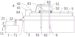
Fig. 1 is a front view of a first embodiment of the present invention;
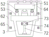
fig. 2 is a right side view of the first embodiment of the present invention;
fig. 3 is a front view of a second spraying mechanism of the present invention;
FIG. 4 is a schematic view of the interior structure of the rainwater collecting mechanism;
fig. 5 is a top view of the first spraying mechanism of the present invention;
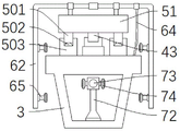
fig. 6 is a right side view of a second embodiment of the present invention.
In the figure: 1. a water storage mechanism; 11. a water storage tank; 12. a water pumping pipe; 2. a rainwater collection mechanism; 21. a water storage tank; 22. a filter plate; 23. a drain pipe; 3. prefabricating a beam box; 4. a drive mechanism; 41. a motor box; 42. an electric slide rail; 43. a moving block; 5. a moving mechanism; 51. moving the trolley; 52. a pulley; 53. a slide rail; 501. a slider; 502. a ball bearing; 503. a chute; 6. a first spraying mechanism; 61. a first shower pipe; 62. a second shower pipe; 63. a water delivery pipe; 64. a first hose; 65. a first nozzle; 7. a second spraying mechanism; 71. a second hose; 72. a support leg; 73. a third shower pipe; 74. and a second spray head.
Detailed Description
Hereinafter, embodiments will be described with reference to the drawings. The embodiments described below do not limit the scope of the invention described in the claims. Further, the entire contents of the configurations shown in the following embodiments are not limited to those necessary as a solution of the invention described in the claims.
Example 1
As shown in fig. 1, 2, 3, 4 and 5, the spray device for maintaining the precast beam comprises a water storage mechanism 1, a precast beam box 3, a first spray mechanism 6 and a second spray mechanism 7, wherein the water storage mechanism 1 is arranged at one side of the precast beam box 3, the first spray mechanism 6 is arranged on the precast beam box 3, the second spray mechanism 7 is arranged in the precast beam box 3, the second spray mechanism 7 is communicated with the water storage mechanism 1, the spray device also comprises a rainwater collection mechanism 2, a driving mechanism 4 and a moving mechanism 5, the rainwater collection mechanism 2 is fixed on the water storage mechanism 1 through screws, the driving mechanism 4 is fixed on the precast beam box 3 through screws, the moving mechanism 5 is arranged on the driving mechanism 4, the rainwater collection mechanism 2 comprises a water storage tank 21, a filter plate 22 and a drain pipe 23, the water storage tank 21 is fixed on the water storage mechanism 1 through screws, the filter plate 22 is fixed inside the water storage tank 21 through screws, for preventing rainwater and impurities in the external environment from entering the water storage tank 21, the bottom of the water storage tank 21 is embedded with a drain pipe 23, the drain pipe 23 is communicated with the water storage mechanism 1, the driving mechanism 4 comprises a motor box 41, an electric slide rail 42 and a moving block 43, the motor box 41 is fixed on the precast beam box 3 through screws, a motor is arranged in the motor box 41, one side of the motor box 41 is provided with the electric slide rail 42, the moving block 43 is connected on the electric slide rail 42 in a sliding manner and used for driving the moving mechanism 5 to move to carry out comprehensive and uniform spraying on the precast beam box 3, the water storage mechanism 1 comprises a water storage tank 11 and a water pumping pipe 12, the water pumping pipe 12 is fixed on the water storage tank 11 through screws, a water pump is arranged on the water pumping pipe 12, the water pumping pipe 12 is communicated with the first spraying mechanism 6 and the second spraying mechanism 7, the moving mechanism 5 comprises a moving trolley 51, a pulley 52 and a slide rail 53, the moving trolley 51 is arranged above the driving mechanism 4, pulleys 52 are fixed at four corners of the bottom of the movable trolley 51 through screws, slide rails 53 are arranged below the pulleys 52, two slide rails 53 are symmetrically arranged about the electric slide rail 42 to realize that the movable mechanism 5 moves above the driving mechanism 4 to drive the first spraying mechanism 6 to move, the slide rails 53 are fixedly connected with the precast beam box 3 through screws, the first spraying mechanism 6 comprises a first spraying pipe 61, a second spraying pipe 62, a water conveying pipe 63, a first hose 64 and a first spray head 65, the first spraying pipe 61 and the second spraying pipe 62 are both fixed on the movable trolley 51 through screws, the water conveying pipe 63 is communicated between the first spraying pipe 61 and the second spraying pipe 62, the first hose 64 is communicated between the first spraying pipe 61 and the water pumping pipe 12 to convey water in the water storage tank 11 into the first spraying pipe 61 and the second spraying pipe 62, the first spraying pipe 61 and the second spraying pipe 62 are both connected with a plurality of first spray heads 65 through threads, the second spraying mechanism 7 comprises a second hose 71, supporting legs 72, a third spraying pipe 73 and second spray heads 74, the third spraying pipe 73 is arranged inside the precast beam box 3, the third spraying pipe 73 is fixedly provided with the two supporting legs 72 through screws, the second hose 71 is communicated between the third spraying pipe 73 and the water pumping pipe 12 and used for conveying water in the water storage tank 11 into the third spraying pipe 73, and the two sides of the third spraying pipe 73 are connected with the second spray heads 74 through threads and used for spraying the inner cavity of the precast beam box 3.
In the above structure: when in use, a proper amount of water is injected into the water storage tank 11, meanwhile, the rainwater flows into the water storage tank 11 through the drain pipe 23 after being filtered by the filter plate 22, then the water pump on the water pumping pipe 12 is started to pump the water in the water storage tank 11 to the first hose 64 and the second hose 71, the second hose 71 feeds water into the third shower pipe 73 and is sprayed out through the second spray head 74, spraying and maintaining the inner cavity of the precast beam box 3, delivering water to the first spraying pipe 61 through the first hose 64, delivering the water to the second spraying pipe 62 through the water delivery pipe 63, the water is sprayed out through the first spray head 65 on the first spray pipe 61 and the second spray pipe 62, at this time, the starting motor box 41 drives the moving block 43 and the moving mechanism 5 to reciprocate on the electric slide rail 42 along the length direction of the electric slide rail 42, namely, the first spraying mechanism 6 is driven to move back and forth on the precast beam box 3, and the spraying maintenance work of the precast beam box 3 is realized through the first spray head 65.
Example 2
As shown in fig. 3, 4, 5, and 6, the difference between the embodiment 2 and the embodiment 1 is that the moving trolley 51, the pulley 52, and the slide rail 53 of the embodiment 1 are replaced by the moving trolley 51, the slider 501, the balls 502, and the slide groove 503, during spraying, the moving block 43 drives the moving mechanism 5 to move back and forth on the electric slide rail 42, and simultaneously the slider 501 slides in the groove of the slide groove 503, and the balls 502 freely rotate in the slide groove 503 to reduce friction, which is beneficial to the movement of the moving mechanism 5.
Finally, it should be noted that: although the present invention has been described in detail with reference to the foregoing embodiments, it will be apparent to those skilled in the art that modifications and variations can be made in the embodiments or in part of the technical features of the embodiments without departing from the spirit and the scope of the invention.
Claims (6)
1. The utility model provides a spray set for maintenance of precast beam box, includes water storage mechanism (1), precast beam box (3), first spray mechanism (6), second spray mechanism (7), water storage mechanism (1) set up in one side of precast beam box (3), first spray mechanism (6) set up in on precast beam box (3), the second spray mechanism (7) set up in precast beam box (3) just the second spray mechanism (7) with water storage mechanism (1) intercommunication, its characterized in that: the rainwater collecting mechanism (2) is fixed on the water storage mechanism (1) through screws, the driving mechanism (4) is fixed on the precast beam box (3) through screws, and the moving mechanism (5) is arranged on the driving mechanism (4);
the rainwater collecting mechanism (2) comprises a water storage tank (21), a filter plate (22) and a drain pipe (23), the water storage tank (21) is fixed on the water storage mechanism (1) through screws, the filter plate (22) is fixed inside the water storage tank (21) through screws, the drain pipe (23) is embedded in the bottom of the water storage tank (21), and the drain pipe (23) is communicated with the water storage mechanism (1);
the driving mechanism (4) comprises a motor box (41), an electric sliding rail (42) and a moving block (43), the motor box (41) is fixed on the precast beam box (3) through screws, a motor is arranged in the motor box (41), the electric sliding rail (42) is arranged on one side of the motor box (41), and the moving block (43) is connected to the electric sliding rail (42) in a sliding mode.
2. The spraying device for precast box girder curing according to claim 1, wherein: the water storage mechanism (1) comprises a water storage tank (11) and a water pumping pipe (12), the water storage tank (11) is fixed with the water pumping pipe (12) through screws, a water pump is arranged on the water pumping pipe (12), and the water pumping pipe (12) is communicated with the first spraying mechanism (6) and the second spraying mechanism (7).
3. The spraying device for precast box girder curing according to claim 1, wherein: the movable mechanism (5) comprises a movable trolley (51), pulleys (52) and a sliding rail (53), the movable trolley (51) is arranged above the driving mechanism (4), the pulleys (52) are fixed at four corners of the bottom of the movable trolley (51) through screws, the sliding rail (53) is arranged below the pulleys (52), the two sliding rails (53) are symmetrically arranged about the driving mechanism (4), and the sliding rails (53) are fixedly connected with the precast beam box (3) through screws.
4. The spraying device for precast box girder curing according to claim 1, wherein: the moving mechanism (5) comprises a moving trolley (51), sliding blocks (501), balls (502) and sliding grooves (503), wherein the moving trolley (51) is arranged above the driving mechanism (4), the two sliding blocks (501) are fixed on the lower surface of the moving trolley (51) through screws, the sliding grooves (503) are arranged below each sliding block (501), the sliding grooves (503) are fixedly connected with the precast beam box (3) through screws, a plurality of balls (502) are arranged in each sliding groove (503), and the balls (502) freely rotate inside the sliding grooves (503).
5. The spraying device for precast box girder curing according to claim 1, wherein: the first spraying mechanism (6) comprises a first spraying pipe (61), a second spraying pipe (62), a water conveying pipe (63), a first hose (64) and a first spray head (65), the first spraying pipe (61) and the second spraying pipe (62) are fixed on the moving mechanism (5) through screws, the water conveying pipe (63) is communicated between the first spraying pipe (61) and the second spraying pipe (62), the first hose (64) is communicated between the first spraying pipe (61) and the water storage mechanism (1), and the first spraying pipe (61) and the second spraying pipe (62) are connected with the first spray heads (65) through threads.
6. The spraying device for precast box girder curing according to claim 1, wherein: the second spraying mechanism (7) comprises a second hose (71), supporting legs (72), third spraying pipes (73) and second spray heads (74), the third spraying pipes (73) are arranged inside the precast beam box (3), the third spraying pipes (73) are fixed with the two supporting legs (72) through screws, the third spraying pipes (73) are communicated with the second hose (71) between the water storage mechanism (1), and the two sides of the third spraying pipes (73) are connected with the plurality of second spray heads (74) through threads.
Priority Applications (1)
| Application Number | Priority Date | Filing Date | Title |
|---|---|---|---|
| CN202120460514.0U CN214819510U (en) | 2021-03-03 | 2021-03-03 | A spray set for maintenance of prefabricated box girder |
Applications Claiming Priority (1)
| Application Number | Priority Date | Filing Date | Title |
|---|---|---|---|
| CN202120460514.0U CN214819510U (en) | 2021-03-03 | 2021-03-03 | A spray set for maintenance of prefabricated box girder |
Publications (1)
| Publication Number | Publication Date |
|---|---|
| CN214819510U true CN214819510U (en) | 2021-11-23 |
Family
ID=78884584
Family Applications (1)
| Application Number | Title | Priority Date | Filing Date |
|---|---|---|---|
| CN202120460514.0U Active CN214819510U (en) | 2021-03-03 | 2021-03-03 | A spray set for maintenance of prefabricated box girder |
Country Status (1)
| Country | Link |
|---|---|
| CN (1) | CN214819510U (en) |
Cited By (2)
| Publication number | Priority date | Publication date | Assignee | Title |
|---|---|---|---|---|
| CN116988398A (en) * | 2023-09-18 | 2023-11-03 | 中交第四航务工程局有限公司 | Cast-in-situ beam construction device and technology |
| CN117021319A (en) * | 2023-09-19 | 2023-11-10 | 四川公路桥梁建设集团有限公司 | A green energy-saving maintenance system and method for prefabricated T-beams |
-
2021
- 2021-03-03 CN CN202120460514.0U patent/CN214819510U/en active Active
Cited By (3)
| Publication number | Priority date | Publication date | Assignee | Title |
|---|---|---|---|---|
| CN116988398A (en) * | 2023-09-18 | 2023-11-03 | 中交第四航务工程局有限公司 | Cast-in-situ beam construction device and technology |
| CN116988398B (en) * | 2023-09-18 | 2025-02-14 | 中交第四航务工程局有限公司 | A cast-in-place beam construction device and process |
| CN117021319A (en) * | 2023-09-19 | 2023-11-10 | 四川公路桥梁建设集团有限公司 | A green energy-saving maintenance system and method for prefabricated T-beams |
Similar Documents
| Publication | Publication Date | Title |
|---|---|---|
| CN205651498U (en) | Prefabricated staircase production line | |
| CN105500518A (en) | Prefabricated stair production line and production method | |
| CN109505626B (en) | The method of using the belt formwork assembly to spray the initial support of the tunnel | |
| CN101143464A (en) | Foaming concrete building block automatic production line | |
| CN103015692B (en) | Automatic spray positioning bracket | |
| CN105002861B (en) | A channel slope lining troweling equipment with pre-pressure and push-leveling functions | |
| CN217270213U (en) | Lining maintenance device of tunnel two-lining trolley | |
| CN205532629U (en) | All -hydraulic central ditch die carrier | |
| CN212948398U (en) | Pouring device convenient to control and used for building construction | |
| CN208247134U (en) | A kind of railway plate die track slot sweeping robot | |
| CN116971618A (en) | High-efficiency energy-saving concrete vibrator | |
| CN207105185U (en) | A kind of small-sized 3D building printing construction equipments that disclosure satisfy that office operation | |
| CN216866716U (en) | A telescopic orbital mobile spray curing bench | |
| CN201151158Y (en) | Automatic production line of foamed concrete blocks | |
| CN220746608U (en) | Cast-in-situ box girder spray curing device | |
| CN222135349U (en) | Prefabricated beam spray curing equipment | |
| CN209699471U (en) | A kind of steam-cured pond of modified form cement electric pole | |
| CN209163479U (en) | A kind of concrete casting device based on bim | |
| CN112431612A (en) | Quick construction pin-connected panel platform truck suitable for flat hole of super large span room | |
| CN217621291U (en) | Assembly line type production device for prefabricated track plate | |
| CN206305426U (en) | A kind of hydraulic pressure stainless steel casting machine | |
| CN216465279U (en) | Automatic spraying and curing equipment for concrete precast block | |
| CN215595025U (en) | A kind of automatic maintenance device for side wall concrete of subway station | |
| CN2325516Y (en) | Multi-function machine vehicle for lining tunnel | |
| CN204976996U (en) | Remove case roof beam health preserving device |
Legal Events
| Date | Code | Title | Description |
|---|---|---|---|
| GR01 | Patent grant | ||
| GR01 | Patent grant |