CN214817869U - Large-clamping-force electric vice with adjustable support - Google Patents

Large-clamping-force electric vice with adjustable support Download PDF

Info

Publication number
CN214817869U
CN214817869U CN202121107985.XU CN202121107985U CN214817869U CN 214817869 U CN214817869 U CN 214817869U CN 202121107985 U CN202121107985 U CN 202121107985U CN 214817869 U CN214817869 U CN 214817869U
Authority
CN
China
Prior art keywords
base
jaw plate
movable jaw
gear
shaped
Prior art date
Legal status (The legal status is an assumption and is not a legal conclusion. Google has not performed a legal analysis and makes no representation as to the accuracy of the status listed.)
Expired - Fee Related
Application number
CN202121107985.XU
Other languages
Chinese (zh)
Inventor
李体仁
辛晓龙
徐士浩
杨德青
Current Assignee (The listed assignees may be inaccurate. Google has not performed a legal analysis and makes no representation or warranty as to the accuracy of the list.)
Shaanxi University of Science and Technology
Original Assignee
Shaanxi University of Science and Technology
Priority date (The priority date is an assumption and is not a legal conclusion. Google has not performed a legal analysis and makes no representation as to the accuracy of the date listed.)
Filing date
Publication date
Application filed by Shaanxi University of Science and Technology filed Critical Shaanxi University of Science and Technology
Priority to CN202121107985.XU priority Critical patent/CN214817869U/en
Application granted granted Critical
Publication of CN214817869U publication Critical patent/CN214817869U/en
Expired - Fee Related legal-status Critical Current
Anticipated expiration legal-status Critical

Links

Images

Landscapes

  • Gripping Jigs, Holding Jigs, And Positioning Jigs (AREA)

Abstract

本实用新型公开了一种可调支撑的大夹持力电动虎钳,所述基座内设置有轨道,轨道内设置有丝杠,所述固定钳口板固定安装在基座尾端,活动钳口置于基座的轨道上方,活动钳口板与活动钳口背面固定连接,活动钳口下方与丝杠连接,所述固定钳口板及活动钳口板的中央开有T形槽,槽内设置有台阶式垫块,所述基座前方设置有电机,电机与齿轮组连接。本实用新型解决了现有虎钳上紧费时费力,操作不方便和需要垫高的的问题,实现了调整加工工件高度和定位、加快上紧速度和增加上紧力等多种功能,并且具有正反两种安装方式,可以提高其使用寿命。

Figure 202121107985

The utility model discloses an adjustable support electric vise with large clamping force. A rail is arranged in the base, a lead screw is arranged in the rail, and the fixed jaw plate is fixedly installed at the tail end of the base and is movable. The jaw is placed above the track of the base, the movable jaw plate is fixedly connected with the back of the movable jaw, and the lower part of the movable jaw is connected with the lead screw. The center of the fixed jaw plate and the movable jaw plate has a T-shaped slot. A stepped spacer is arranged in the groove, a motor is arranged in front of the base, and the motor is connected with the gear set. The utility model solves the problems of time-consuming and laborious tightening, inconvenient operation and the need for pad height of the existing vise, and realizes various functions such as adjusting the height and positioning of the processed workpiece, accelerating the tightening speed and increasing the tightening force, and has the advantages of Both positive and negative installation methods can improve its service life.

Figure 202121107985

Description

Large-clamping-force electric vice with adjustable support
Technical Field
The utility model belongs to pincers worker clamping instrument field, concretely relates to big clamping-force electric vice of adjustable support.
Background
A vise, also called a table vise, is generally used for positioning and clamping square workpieces, and is a general fixture necessary for the bench worker to work. Traditional vice passes through the manual tightening of spanner, leads to the handling inefficiency to manual tightening process is inconvenient application of force sometimes, leads to the clamping to waste time and energy. The condition that the workpiece slides down can happen when the workpiece clamped by the traditional vice is processed and is subjected to downward force, and meanwhile, when the workpiece clamped by the traditional vice is thinner, additional objects are often required to be found and are lifted, so that the processing quality can be influenced, and the processing process is caused to be dangerous.
Disclosure of Invention
In view of this, the utility model provides a big clamping-force electric vice of adjustable support has solved current vice and has tightened time and energy consuming, operates inconvenient and need fill up high problem.
The embodiment of the utility model provides a technical scheme is:
a kind of adjustable supported large clamping force electric vice, including the base, fixed jaw plate, activity jaw, lead screw, there are orbits in the said base, there are lead screws in the orbit, the said fixed jaw plate is fixedly mounted on the foot end of the base, the activity jaw is placed above orbit of the base, the activity jaw plate is fixedly connected with back of activity jaw, activity jaw below is connected with lead screw;
the center of the fixed jaw plate and the center of the movable jaw plate are provided with T-shaped grooves, slidable T-shaped blocks are arranged in the grooves, and stepped cushion blocks are fixedly arranged on the T-shaped blocks;
the motor is arranged in front of the base and connected with the gear set, the gear set comprises a pinion, a first intermediate gear, a second intermediate gear and a bull gear, wherein the pinion and the second intermediate gear are sequentially and fixedly installed on a motor gear shaft of the motor, and the bull gear and the first intermediate gear are sequentially and fixedly installed on a screw rod gear shaft of the screw rod.
The base is L type structure, and the track setting is in the short platform of L type structure, and fixed jaw board back is connected fixedly through hexagon socket head cap screw with the vertical board of L type structure.
And a threaded hole is formed below the movable jaw and is in threaded fit with the screw rod.
The fixed jaw plate and the step cushion block are provided with step tooth-shaped structures which are meshed with each other.
And a threaded hole is formed in the middle of the T-shaped block, a through hole is formed in the middle of the stepped cushion block, and a second inner hexagonal bolt is in threaded fit with the T-shaped block and fixedly connects the stepped cushion block with the T-shaped block.
Compared with the prior art, the beneficial effects of the utility model are that:
1. the vice is equipped with step cushion, can play the effect of adjustment processing work piece height and location.
2. The utility model discloses drive the motion of lead screw by motor drive gear axle, the gear has multiple cooperation mode simultaneously, has the effect of accelerating the effect of tightening speed and increase.
3. The utility model discloses vice jaw board has tow kinds of positive and negative mounting means, can improve its life.
Drawings
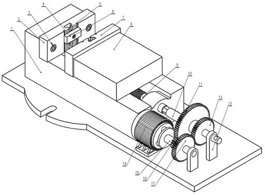
Fig. 1 is a schematic structural view of the present invention;
FIG. 2 is a schematic view of the elevating structure of the present invention;
FIG. 3 is a schematic view of the power structure of the present invention;
in the drawing, 1, a base, 2, a fixed jaw plate, 3, a first hexagon socket head cap screw, 4, a stepped cushion block, 5, a T-shaped block, 6, a second hexagon socket head cap screw, 7, a movable jaw plate, 8, a movable jaw, 9, a screw, 10, a screw gear shaft, 11, a large gear, 12, a first middle gear, 13, a support frame, 14, a motor, 15, a motor gear shaft, 16, a small gear, 17 and a second middle gear are arranged.
Detailed Description
The present invention will be described in detail with reference to the following embodiments.
As shown in fig. 1, the utility model discloses a base 1, fixed vice-mouth board 2, a hexagon socket head cap screw 3, activity vice-mouth board 7, movable vice-mouth 8, lead screw 9, fixed vice-mouth board 2 is through a hexagon socket head cap screw 3 fixed mounting at the afterbody of base 1, movable vice-mouth 8 is arranged in on the track of base 1, activity vice-mouth board 7 fixed mounting is on movable vice-mouth 8, movable vice-mouth 8 below is provided with the screw hole, produce screw-thread fit with lead screw 9, lead screw 9 installs on base 1, when lead screw 9 takes place to rotate, movable vice-mouth 8 takes place the back-and-forth movement, make the distance between fixed vice-mouth board 2 and the activity vice-mouth board 7 produce corresponding increase or reduce, realize relaxing or the tight action of clamp.
As shown in figure 2, the utility model discloses but bed hedgehopping structure is including fixed jaw board 2, stepped cushion 4, T-shaped piece 5, two 6 of hexagon socket head cap screw, activity jaw board 7, wherein all have step profile of tooth structure on fixed jaw board 2 and the stepped cushion 4, can interlock each other. The middle of the fixed jaw plate 2 is provided with a T-shaped groove, the T-shaped block 5 slides in the T-shaped groove, the middle of the T-shaped block 5 is provided with a threaded hole, the middle of the stepped cushion block 4 is provided with a through hole, and the inner hexagonal bolt II 6 is in threaded fit with the T-shaped block 5 to realize the fixation of the stepped cushion block 4. The movable jaw plate 7 has a structure symmetrical to that of the movable jaw plate, namely, a step cushion block with the same shape is installed, and the movable jaw plate and the step cushion block realize the function of heightening a workpiece by the vice.
As shown in fig. 3, the power part of the present invention includes a motor 14, a motor gear shaft 15, a pinion 16, a support frame 13, a middle gear 12, a gear wheel 11, a lead screw gear shaft 10, wherein the motor 14 is fixedly mounted on the base 1, the left end of the motor gear shaft 15 is connected with the motor 14, the right end thereof is mounted on the support frame 13, and the pinion 16 and the middle gear 17 are fixed on the motor gear shaft 15. The large gear 11 and the first middle gear 12 are fixedly arranged on a screw rod gear shaft 10, the left end of the screw rod gear shaft 10 is connected with a screw rod 9, the right end of the screw rod gear shaft is arranged on a support frame 13, and the right end of the screw rod gear shaft is provided with a pull hole. When the screw rod gear is used, the screw rod gear shaft 10 is pushed leftwards, and the first middle gear 12 is matched with the second middle gear 17. When the motor 14 drives the motor gear shaft 15 to rotate, the screw rod gear shaft 10 rotates along with the motor gear shaft to finish the action of quick tightening, the screw rod gear shaft 10 is pulled rightwards to enable the large gear 11 to be matched with the small gear 16, and the motor 14 rotates to finish the action of increasing the clamping force. Otherwise, the vice can be loosened and quickly withdrawn.
The content of the present invention is not limited to the examples, and any equivalent transformation adopted by the technical solution of the present invention is covered by the claims of the present invention by those skilled in the art through reading the present invention.
Claims (5)

1. The utility model provides a big clamping-force electric vice of adjustable support which characterized in that:
the adjustable jaw plate comprises a base (1), a fixed jaw plate (2), a movable jaw plate (7), a movable jaw (8) and a screw (9), wherein a track is arranged in the base (1), the screw (9) is arranged in the track, the fixed jaw plate (2) is fixedly arranged at the tail end of the base (1), the movable jaw (8) is arranged above the track of the base (1), the movable jaw plate (7) is fixedly connected with the back of the movable jaw (8), and the lower part of the movable jaw (8) is connected with the screw (9);
the centers of the fixed jaw plate (2) and the movable jaw plate (7) are provided with T-shaped grooves, slidable T-shaped blocks (5) are arranged in the grooves, and stepped cushion blocks (4) are fixedly arranged on the T-shaped blocks (5);
base (1) the place ahead is provided with motor (14), and motor (14) are connected with the gear train, the gear train includes pinion (16), well gear (12), well gear two (17) and gear wheel (11), wherein pinion (16) and well gear two (17) fixed mounting in proper order are in motor gear shaft (15) of motor (14), and gear wheel (11) and well gear one (12) are in proper order fixed mounting in lead screw gear shaft (10) of lead screw (9).
2. The adjustably supported high clamp force electric vise of claim 1, wherein:
the base (1) is of an L-shaped structure, the rail is arranged in a short platform of the L-shaped structure, and the back of the fixed jaw plate (2) is fixedly connected with the vertical plate of the L-shaped structure through a hexagon socket head cap screw I (3).
3. The adjustably supported high clamp force electric vise of claim 1, wherein:
and a threaded hole is formed below the movable jaw (8) and is in threaded fit with the screw rod (9).
4. The adjustably supported high clamp force electric vise of claim 1, wherein:
the fixed jaw plate (2) and the step cushion block (4) are provided with step tooth-shaped structures which are meshed with each other.
5. The adjustably supported high clamp force electric vise of claim 1, wherein:
the middle of the T-shaped block (5) is provided with a threaded hole, the middle of the stepped cushion block (4) is provided with a through hole, and the inner hexagonal bolt II (6) is in threaded fit with the T-shaped block (5) and fixedly connects the stepped cushion block (4) with the T-shaped block (5).
CN202121107985.XU 2021-05-24 2021-05-24 Large-clamping-force electric vice with adjustable support Expired - Fee Related CN214817869U (en)

Priority Applications (1)

Application Number Priority Date Filing Date Title
CN202121107985.XU CN214817869U (en) 2021-05-24 2021-05-24 Large-clamping-force electric vice with adjustable support

Applications Claiming Priority (1)

Application Number Priority Date Filing Date Title
CN202121107985.XU CN214817869U (en) 2021-05-24 2021-05-24 Large-clamping-force electric vice with adjustable support

Publications (1)

Publication Number Publication Date
CN214817869U true CN214817869U (en) 2021-11-23

Family

ID=78775994

Family Applications (1)

Application Number Title Priority Date Filing Date
CN202121107985.XU Expired - Fee Related CN214817869U (en) 2021-05-24 2021-05-24 Large-clamping-force electric vice with adjustable support

Country Status (1)

Country Link
CN (1) CN214817869U (en)

Cited By (1)

* Cited by examiner, † Cited by third party
Publication number Priority date Publication date Assignee Title
CN114939836A (en) * 2022-05-27 2022-08-26 上海市高级技工学校 Vice with lifting cushion block

Cited By (1)

* Cited by examiner, † Cited by third party
Publication number Priority date Publication date Assignee Title
CN114939836A (en) * 2022-05-27 2022-08-26 上海市高级技工学校 Vice with lifting cushion block

Similar Documents

Publication Publication Date Title
CN117506775A (en) A clamping tool for cylinder liner processing
CN203317274U (en) Hoisting type clamping device
CN220903015U (en) Positioning jig for multidirectional processing of handle
CN215146991U (en) Clamping equipment for processing I-steel
CN112719987A (en) Special aluminum pipe punching clamp for 2.5-shaft engraving machine and 2.5-shaft engraving machine
CN220094300U (en) Bench vice for bench worker
CN223419418U (en) Automatic screw locking machine fixture for two-wheeled electric vehicles
CN207026842U (en) Reinforcement plate fixture for left and right pillars of rear door frame for automobile manufacturing
CN219211757U (en) Milling fixture device for rear bracket
CN114453688A (en) Traction piece tapping screw clamp and using method thereof
CN206912743U (en) A kind of machining center fixture with correcting structure
CN219445015U (en) General type robot upset tool
CN209578902U (en) Vertical machining center workstation
CN221270403U (en) Lathe of frock clamp is conveniently installed
CN224027039U (en) Thin-wall part clamping tool
CN201217093Y (en) Apparatus for milling flutes
CN221716163U (en) A double-head screw assembly tool
CN217317533U (en) Accurate positioning device for plane grinding machine
CN221659065U (en) A milling slot quality inspection positioning fixture
CN223572341U (en) Subway water tank flange seat welding frock
CN218697932U (en) Guide rail machining clamp
CN223441690U (en) A workpiece clamping mechanism for a vertical machining center
CN219665575U (en) An auxiliary fixture based on automobile welding
CN224255123U (en) Machining fixture and machining tool
CN222353478U (en) Angle-adjustable test fixture

Legal Events

Date Code Title Description
GR01 Patent grant
GR01 Patent grant
CF01 Termination of patent right due to non-payment of annual fee

Granted publication date: 20211123

CF01 Termination of patent right due to non-payment of annual fee