Drainage bottle hydrops capacity monitoring device based on cardiovascular internal medicine nursing
Technical Field
The utility model relates to an internal medicine nursing technical field specifically is a drainage bottle hydrops capacity monitoring device based on cardiovascular internal medicine nursing.
Background
Cardiovascular internal medicine operation hand needs introduce the drainage tube with patient's operation position to outwards draw forth the hydrops with the affected part through the drainage tube, the hydrops of drawing forth flow in the other end and lie in subaerial drainage bottle, and the drainage bottle is the negative pressure bottle structure, with the slow suction bottle of hydrops in vivo, with the stock that reduces postoperative patient's hydrops, reduces the operation department and infects.
Current drainage bottle is when using, because inside negative pressure intensity can not be adjusted, when drawing forth the hydrops for the patient, because the extraction speed is too fast, often can cause the patient uncomfortable, and, the type of negative pressure drainage bottle has the multiple, it is difficult to fix the negative pressure drainage bottle of different grade type, general hospital is when using negative pressure drainage bottle extraction hydrops, often can hang on a pole, or place on the desk, and the safeguard measure to negative pressure drainage bottle, because the body makes glass, the surface is being connected the drainage tube with the patient, the patient pulls the negative pressure drainage bottle very easily when removing, make it drop, lead to broken problem.
SUMMERY OF THE UTILITY MODEL
Technical problem to be solved
Not enough to prior art, the utility model provides a drainage bottle hydrops capacity monitoring device based on cardiovascular internal medicine nursing has solved the problem of proposing in the above-mentioned background art.
(II) technical scheme
In order to achieve the above purpose, the utility model discloses a following technical scheme realizes: the utility model provides a drainage bottle hydrops capacity monitoring device based on nursing of cardiovascular internal medicine, includes negative pressure drainage bottle and alarm, the top threaded connection of negative pressure drainage bottle has sealed lid, the top fixedly connected with drainage tube of sealed lid, the surface threaded connection of drainage tube has the governing valve, the bottom swing joint of negative pressure drainage bottle has the right angle to drag, the top fixed connection mount that the right angle dragged, the one end fixedly connected with ring of mount presss from both sides, the surface threaded connection that the ring pressed from both sides has adjusting screw, adjusting screw's one end fixedly connected with arc clamp.
Optionally, one side of the fixing frame is connected with a rectangular rod through screw threads, and one side of the rectangular rod is fixedly connected with a placing frame.
Optionally, the method is characterized in that: the inside wall sliding connection of rack has the alarm, the surface fixed connection of alarm has the spool.
Optionally, one end of the line pipe is fixedly connected with a floating ball probe, and the outer surface of the floating ball probe is in threaded connection with a nut.
Optionally, the bottom of the rectangular rod is fixedly connected with a base, and the outer surface of the base is fixedly connected with a circular ring.
Optionally, the number of the negative pressure drainage bottles is two, and the upper parts of the two negative pressure drainage bottles are fixedly connected with handles.
(III) advantageous effects
The utility model provides a drainage bottle hydrops capacity monitoring device based on nursing of cardiovascular internal medicine possesses following beneficial effect:
1. this drainage bottle hydrops capacity monitoring device based on nursing of cardiovascular internal medicine through the setting of drainage tube and governing valve, makes the device when using negative pressure drainage bottle to extract the hydrops for the patient, plays adjustable effect, has avoided the inside negative pressure of negative pressure drainage bottle too high, and extraction speed is too fast, makes the patient produce uncomfortable problem.
2. This drainage bottle hydrops capacity monitoring device based on nursing of cardiovascular internal medicine through the setting of arc clamp and adjusting screw, makes the device can fix the centre gripping to the negative pressure drainage bottle of different models, drags fixed connection's mode through arc frame and right angle, avoids the patient mistake to touch negative pressure drainage bottle, makes its broken condition that drops.
Drawings
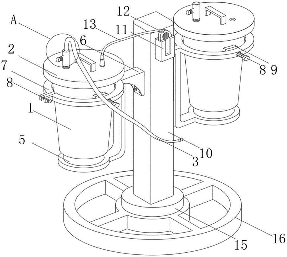
FIG. 1 is a schematic structural view of the present invention;
FIG. 2 is a schematic view of the floating ball probe of the present invention;
fig. 3 is an enlarged schematic view of a portion a in fig. 1 according to the present invention.
In the figure: 1. a negative pressure drainage bottle; 2. a sealing cover; 3. a drainage tube; 4. adjusting a valve; 5. dragging at right angle; 6. a fixed mount; 7. a circular ring clamp; 8. adjusting screws; 9. an arc-shaped clamp; 10. a rectangular bar; 11. placing a rack; 12. an alarm; 13. a conduit; 14. a floating ball probe; 15. a base; 16. a circular ring.
Detailed Description
The technical solutions in the embodiments of the present invention will be described clearly and completely with reference to the accompanying drawings in the embodiments of the present invention, and it is obvious that the described embodiments are only some embodiments of the present invention, not all embodiments.
Referring to fig. 1 to 3, the present invention provides a technical solution: a drainage bottle hydrops volume monitoring device based on cardiovascular internal medicine nursing comprises a negative pressure drainage bottle 1 and an alarm 12, wherein electrical components appearing in the negative pressure drainage bottle are electrically connected with an external main controller and 220V mains supply, and the main controller can be a conventional known device controlled by a computer and the like;
in order to effectively enable the negative pressure drainage bottle 1 to be convenient to disassemble and also to play a role in sealing, the top of the negative pressure drainage bottle 1 is in threaded connection with a sealing cover 2, in order to effectively enable the device to play an adjustable role in using the negative pressure drainage bottle to extract accumulated liquid for a patient, and avoid the problems that the negative pressure in the negative pressure drainage bottle is too high, the extraction speed is too high, and the patient feels uncomfortable, the top of the sealing cover 2 is fixedly connected with a drainage tube 3, and the outer surface of the drainage tube 3 is in threaded connection with an adjusting valve 4;
in order to effectively avoid the situation that a patient mistakenly touches the negative pressure drainage bottle to drop and crush the negative pressure drainage bottle, the bottom of the negative pressure drainage bottle 1 is movably connected with a right-angle mop 5, the top of the right-angle mop 5 is fixedly connected with a fixing frame 6, one end of the fixing frame 6 is fixedly connected with a circular clamp 7, in order to effectively enable the device to fixedly clamp the negative pressure drainage bottles of different models, the outer surface of the circular clamp 7 is in threaded connection with an adjusting screw 8, one end of the adjusting screw 8 is fixedly connected with an arc clamp 9, and in order to provide a placeable area for an alarm 12;
one side of the fixing frame 6 is connected with a rectangular rod 10 through screw threads, one side of the rectangular rod 10 is fixedly connected with a placing frame 11, the inner side wall of the placing frame 11 is connected with an alarm 12 in a sliding mode, and the outer surface of the alarm 12 is fixedly connected with a wire pipe 13;
in order to effectively enable the alarm 12 to play a role of alarming, the floating ball probe 14 at one end of the line tube 13 is put in, accumulated liquid in the negative pressure drainage bottle 1 is hidden behind the floating ball probe 14, the floating ball probe 14 floats upwards, so that a circuit in the line tube is electrified, the alarm 12 gives out alarming sound, the floating ball probe 14 is fixedly connected to one end of the line tube 13, the nut is connected to the outer surface of the floating ball probe 14 through threads, the base 15 is fixedly connected to the bottom of the rectangular rod 10, the circular rings 16 are fixedly connected to the outer surface of the base 15, the number of the negative pressure drainage bottles 1 is two, and handles are fixedly connected to the upper parts of the two negative pressure drainage bottles 1.
The utility model discloses in, the device's working procedure as follows:
1. one end of the drainage tube 3 is connected with the hydrops of the patient by the medical staff, and the other end is connected with the negative pressure drainage bottle 1;
2. after the steps are completed, the medical personnel place the negative pressure drainage bottle 1 in the circular ring clamp 7, and rotate the adjusting screw to enable the arc clamp 9 to clamp the negative pressure drainage bottle 1;
3. after the steps are completed, the speed of the negative pressure drainage bottle 1 is controlled by rotating the regulating valve 4 when the accumulated liquid is pumped;
4. after the steps are completed, the alarm 12 is placed in the placing rack 11, and the floating ball probe 14 is placed in the negative pressure drainage bottle 1.
The above, only be the concrete implementation of the preferred embodiment of the present invention, but the protection scope of the present invention is not limited thereto, and any person skilled in the art is in the technical scope of the present invention, according to the technical solution of the present invention and the utility model, the concept of which is equivalent to replace or change, should be covered within the protection scope of the present invention.