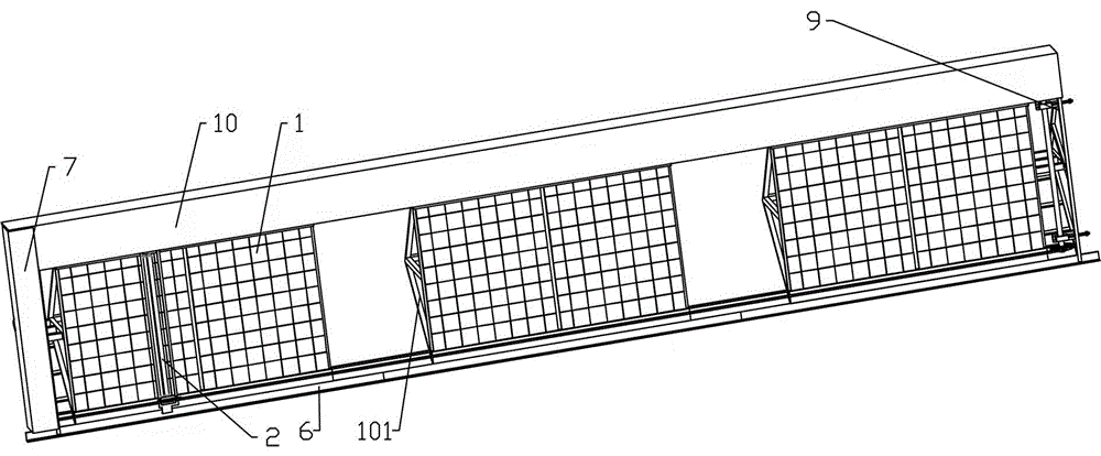
Solar photovoltaic cleaning robot device
Technical Field
The invention relates to a solar photovoltaic cleaning robot device, and belongs to the technical field of cleaning of photovoltaic solar panels.
Background
Photovoltaic power generation is one of green energy, and is paid attention by researchers at home and abroad. The light energy resources in China are uniformly distributed, and 76% of the area of China is full of illumination, so that the solar photovoltaic power generation system has a good foundation for photovoltaic power generation. In addition, compared with hydroelectric power, wind power, nuclear power and the like, the photovoltaic power generation has the advantages of no pollution, low noise, mature application technology, safety, reliability and the like, and is widely applied to the industrial and civil fields.
Due to the influence of weather environment (haze, rain, snow, sand and dust, oil stain) and weather conditions, the pollution phenomenon of the photovoltaic solar panel is inevitable, the light transmittance is directly influenced, and the power generation amount is limited. In addition, the dirt is very easily to cause the hot spot effect of the solar panel now, leads to the damage of photovoltaic module, and then directly influences its life.
At present, the cleaning mode of the photovoltaic solar panel mainly comprises two types, namely manual cleaning, mechanical cleaning and automatic cleaning robot cleaning. The problems of labor occupation, high labor intensity, multiple potential safety hazards, difficulty in ensuring the cleaning frequency, easiness in scratching the board surface and the like exist in manual cleaning; the mechanical cleaning has the advantages of saving manpower and material resources and improving the cleaning efficiency, but the investment cost is higher, and the accessories of the mechanical cleaning are additionally provided with protective facilities such as heat preservation and the like; the development of the automatic cleaning robot is a hot spot at present, the automatic cleaning robot integrates multidisciplinary knowledge of machinery, electric control, detection and the like, but the automatic cleaning robot is mostly in a laboratory stage, the load of the automatic cleaning robot is an important problem, and meanwhile, the automatic cleaning robot is high in manufacturing cost and complex in use and maintenance.
Disclosure of Invention
The invention provides a solar photovoltaic cleaning robot device, which solves the defects of high cost of manpower and material resources, low operation efficiency, low operation safety and the like of the conventional cleaning device, and greatly improves the mechanization and automation degree of cleaning a solar panel.
In order to achieve the purpose, the invention adopts the technical scheme that:
solar photovoltaic cleaning robot device includes:
the upper track and the lower track are arranged at the edge positions of the upper end and the lower end of the inclined solar panel;
the cleaning roller is positioned on the solar panel and rotates to clean surface dust;
the traveling mechanism comprises an upper traveling mechanism and a lower traveling mechanism, the upper traveling mechanism moves on the upper track, the lower traveling mechanism moves on the lower track, and the upper end and the lower end of the cleaning roller are respectively arranged on the upper traveling mechanism and the lower traveling mechanism;
the driving mechanism drives the upper traveling mechanism to travel along the upper rail, and the lower traveling mechanism travels along the lower rail; the solar panels are arranged in an inclined mode, each group is formed by at least two solar panels which are arranged in a close-by-close mode, and the upper track and the lower track between every two adjacent solar panels are continuously connected.
Preferably, the upper traveling mechanism comprises a rack, a gear set, a limiting wheel and an upper traveling frame, the gear set and the limiting wheel are arranged on the upper traveling frame, the gear set comprises a large gear and two steering gears, the large gear is meshed with the rack, the steering gear a is coaxial with the large gear, the steering gear b is meshed with the steering gear a, wheel shafts of the steering gear a and the steering gear b are respectively connected with the two cleaning rollers which are arranged in parallel, power is transmitted between the cleaning rollers through the gears, the rotating directions of the two cleaning rollers are opposite, the upper traveling frame is connected with the driving mechanism, and the limiting wheel moves along the upper track.
Preferably, the lower traveling mechanism includes a lower traveling frame and lower traveling wheels, the lower rail includes two vertical rail surfaces, and the lower traveling wheels are divided into two groups of mutually vertical wheel axles and travel on the two vertical rail surfaces respectively.
Further preferably, the U-shaped track is arranged below the rack and serves as an upper track, the limiting wheels move in the U-shaped track, the driving mechanism comprises a circulating chain, a driving shaft, a driving chain wheel, a driven chain wheel and a driving motor, the circulating chain, the driving shaft, the driving chain wheel, the driven chain wheel and the driving motor are arranged on the upper portion and the lower portion of the solar panel, the driving chain wheel, the driven chain wheel and the driving shaft are arranged on the driven shaft, the driving shaft and the driven shaft are arranged on two sides of the solar panel respectively, and the upper walking frame and the lower walking frame are fixed on the chain.
Preferably, the chain tensioning mechanism is arranged on the other side, opposite to the driving shaft, of the solar panel and comprises a tensioning frame, a tensioning slide way, a tensioning slide block, a tensioning spring and a positioning screw rod, the driven shaft is arranged on the tensioning slide block, the tensioning slide block is arranged on the tensioning slide way, the direction of the tensioning slide way is the same as the direction of the circulating motion of the chain, one end of the positioning screw rod is fixed on the tensioning slide block, the other end of the positioning screw rod penetrates through the tensioning frame and is sleeved with the tensioning spring, and a positioning nut is arranged at the rear end of the tensioning spring by the positioning screw rod.
Preferably, a roller covering part is arranged between the upper travelling mechanism and the lower travelling mechanism, and the roller covering part covers the upper part of the cleaning roller.
Preferably, the upper track is provided with a track covering piece which covers the track to prevent falling objects from entering the gear and chain wheel transmission mechanism.
Preferably, a U-shaped rail is arranged below the rack and serves as an upper rail, the limiting wheel moves in the U-shaped rail, the driving structure is a pull rope arranged on the upper traveling mechanism or the lower traveling mechanism, and the other end of the pull rope is tied at the edge of the side of the solar panel.
Preferably, the driving mechanism comprises a driving motor connected with a wheel shaft of the large gear, a speed change mechanism, a storage battery and a charging plug, the driving motor is connected with an input shaft of the speed change mechanism, an output shaft of the speed change mechanism is connected with the cleaning roller through a steering gear, the storage battery and the charging plug are arranged on the upper walking frame, the charging plug protrudes out of the upper walking frame structure, a charging jack is arranged at the end part of a walking track of the upper walking frame on the solar panel, the charging plug is inserted into the charging jack to charge the storage battery when the upper walking frame walks to the end part of the track, and the storage battery provides a driving power supply for the driving motor.
Further preferably, the upper track is divided into a walking rail and a limiting round rod, walking wheels are further arranged on the upper walking mechanism, the walking wheels move on the walking rail, the limiting wheels are located below the limiting round rod, the walking rail and the limiting round rod limit the upper walking mechanism to move along the upper track direction, the walking wheels and the limiting wheels are located above and below the upper walking frame, and the walking rails and the limiting round rod clamp the walking wheels and limit the walking wheels to be not separated from the upper track.
The device has the advantages that: (1) mechanization and automation: the cleaning of the solar panel is automatically realized by adopting an electromechanical control technology and a mechanical transmission technology without the participation of operators; (2) the fault rate is low, be convenient for maintain: the solar panel cleaning device adopts traditional mature parts such as chains, ropes and gears to realize the cleaning operation function, has stable mechanical performance, mature transmission form, difficult failure and convenient maintenance; (3) the investment is less, the realization is easy, the energy consumption is low: this patent design device is based on current solar panel design, and its basic mechanical structure adopts steel and spare part commonly used to build the completion, and the small investment just easily realizes. In addition, the design device adopts one power source to realize a plurality of movements, thereby greatly reducing the energy consumption.
Drawings
Figure 1 is a perspective view of embodiment 1 of the present invention,
figure 2 is a perspective view of embodiment 1 of the present invention with the rail cover removed,
fig. 3 is a partial structural view of a traveling mechanism in embodiment 1 of the present invention,
fig. 4 is a structural view of a descending structure according to embodiment 1 of the present invention,
figure 5 is a chain tensioner mechanism diagram of embodiment 1 of the present invention,
figure 6 is a perspective view of embodiment 2 of the present invention,
figure 7 is a perspective view of embodiment 2 of the invention with the rail cover removed,
fig. 8 is a partial configuration view of a traveling mechanism in embodiment 2 of the present invention i,
figure 9 is a partial configuration diagram ii of a traveling mechanism in embodiment 2 of the present invention,
reference numerals:
1. solar panel, 2, cleaning roller, 3, upper running gear, 4, lower running gear, 5, upper track, 6, lower track, 7, actuating mechanism, 8, cylinder covering, 9. Chain tensioning mechanism, 10, track covering part, 11 control box, 101 photovoltaic support, 301, rack, 302, bull gear, 303, spacing wheel, 304, upward walking frame, 305, walking wheel, 306, steering gear a, 307, steering gear b, 401, downward walking frame, 501, walking rail, 502, spacing round rail, 503, U type track. 504, spacing round bar, 502, lower traveling wheel, 701, circulating chain, 702, driving chain wheel, 703, driving shaft, 704, driven chain wheel, 705, driven shaft, 706, driving motor, 707, speed change mechanism, 708, storage battery, 709, charging plug, 710, charging jack, 901, tensioning frame, 902, tensioning slideway, 903, positioning screw, 904, tensioning spring, 905, nut, 906 and tensioning slider.
Detailed Description
The utility model discloses a concrete mechanism is as shown in the figure, and solar panel 1 sets up for the slope, and the lower part sets up the photovoltaic support and supports, and every group is two at least adjacent arrangements.
The utility model discloses solar photovoltaic cleaning robot device includes track 5 and lower track 6, cleaning roller 2, running gear and drive structure. The upper rail 5 and the lower rail 6 are respectively arranged at the edge positions of the upper end and the lower end of the inclined solar panel 1. The upper track 5 and the lower track 6 between the adjacent solar panels 1 are continuously connected. The cleaning roller 2 is positioned on the solar panel 1 and rotates to clean surface dust, the cleaning roller 2 is arranged in parallel, the cleaning roller and the cleaning roller transmit power through gears, and the rotating directions of the two cleaning rollers are opposite.
The traveling mechanism comprises an upper traveling mechanism 3 and a lower traveling mechanism 4, the upper traveling mechanism 3 moves on an upper rail 5, the lower traveling mechanism 4 moves on a lower rail 6, and the upper end and the lower end of the cleaning roller 2 are respectively arranged on the upper traveling mechanism 3 and the lower traveling mechanism 4; and the driving mechanism 7 drives the upper traveling mechanism 3 to travel along the upper track 5, and the lower traveling mechanism 4 to travel along the lower track 6. A walking frame is arranged between the upper walking mechanism 3 and the lower walking mechanism 4, a roller covering part is arranged on the walking frame, and the roller covering part covers the upper part of the cleaning roller.
The upper rail is provided with a rail covering part. The upper track 5 is provided with a track covering piece which shields the track to prevent falling objects from entering the gear and chain wheel transmission mechanism.
Embodiment 1 of a drive structure, as shown in fig. 1, 2, 3, 4 and 5.
The traveling mechanism and the driving mechanism are further explained: the upper traveling mechanism 3 comprises a rack 301, a gear set, a limiting wheel 303 and an upper traveling frame 304, the gear set and the limiting wheel 303 are arranged on the upper traveling frame 304, the gear set comprises a large gear 302 and two steering gears, the large gear 302 is meshed with the rack 301, the steering gear a306 is coaxial with the large gear 302, the steering gear b307 is meshed with the steering gear a306, wheel shafts of the steering gear a and the steering gear b307 are respectively connected with the two cleaning rollers 2, the two cleaning rollers 2 are arranged in parallel, the two cleaning rollers transmit power through gears, the rotating directions of the two cleaning rollers are opposite, the upper traveling frame 304 is connected with the driving mechanism 7, and the limiting wheel 303 moves along the upper track 5. The lower running mechanism 4 includes a lower running frame 401 and lower running wheels 402, the lower rail 6 is composed of two vertical rail surfaces, and the lower running wheels 402 are divided into two groups with mutually vertical wheel shafts and run on the two vertical rail surfaces respectively.
A U-shaped rail 503 is arranged below the rack 301 to serve as the upper rail 5, and the limiting wheel 303 moves in the U-shaped rail 503. The driving mechanism 7 includes an endless chain 701 disposed on the upper and lower portions of the solar panel 1, a driving shaft 703, a driving sprocket 702 disposed on the driving shaft 703, a driven sprocket 704 disposed on the driven shaft 705, and a driving motor 706 for driving the driving shaft 703 to rotate, the driving shaft 703 and the driven shaft 705 are disposed on both sides of the solar panel 1, respectively, and the upper traveling frame 304 and the lower traveling frame 401 are fixed to the chain.
The other side of the solar panel 1 opposite to the driving shaft 703 is provided with a chain tensioning mechanism 9, the chain tensioning mechanism 9 comprises a tensioning frame, a tensioning slide way, a tensioning slide block, a tensioning spring and a positioning screw rod, the driven shaft 705 is arranged on the tensioning slide block, the tensioning slide block is arranged on the tensioning slide way, the direction of the tensioning slide way is the same as the direction of the circulating motion of the chain, one end of the positioning screw rod is fixed on the tensioning slide block, the other end of the positioning screw rod penetrates through the tensioning frame and is sleeved with the tensioning spring, and a positioning nut is arranged at the rear end of the tensioning spring by the positioning screw rod.
The working principle is as follows: the driving motor drives the chain wheel to move, the chain wheel drives the chain to rotate, the chain moves to drive the gear and the rack to move in a meshed mode, the gear moves to drive the gear and the gear to move synchronously, the gear moves to drive the two cleaning rollers with opposite rotating directions to move, and therefore automatic cleaning of the solar photovoltaic cell panel is achieved. The operation direction of the last cleaning roller is opposite to the movement direction of the chain, so that the photovoltaic solar panel can be cleaned conveniently.
Embodiment 2 of another drive configuration, fig. 6, 7, 8, 9 and 4.
The upper traveling mechanism 3 comprises a rack 301, a gear set, a limiting wheel 303 and an upper traveling frame 304, the gear set and the limiting wheel 303 are arranged on the upper traveling frame 304, the gear set comprises a large gear 302 and a driving gear, the large gear 302 and the driving gear are meshed with the rack 301, and the large gear 302 and the driving gear are coaxial. The upper traveling frame 304 is connected to the driving mechanism 7, and the limit wheels 303 move along the upper rail 5. The lower running mechanism 4 comprises a lower running frame 401 and lower running wheels 402, the lower track 6 is composed of two vertical track surfaces, and the lower running wheels 402 are divided into two groups with mutually vertical wheel shafts and respectively run on the two vertical track surfaces.
The driving mechanism 7 comprises a driving motor 706 connected with the wheel axle of the gearwheel 302, a speed change mechanism 707, a storage battery and a charging plug, the driving motor 706 is connected with the input shaft of the speed change mechanism 707 and a driving gear, the output shaft of the speed change mechanism 707 is connected with two cleaning rollers, and the two cleaning rollers are parallel and rotate in opposite directions. The driving motor 706 drives the driving gear and drives the large gear to move along the rack in a meshing manner. The driving motor drives the two cleaning rollers to rotate after the rotating speed of the speed change mechanism 707 is adjusted.
The storage battery and the charging plug are arranged on the upper walking frame 304, the charging plug protrudes out of the structure of the upper walking frame 304, a charging jack is arranged at the end part of the walking rail 501 of the upper walking frame 304 on the solar panel 1, when the upper walking frame 304 walks to the end part of the rail, the charging plug is inserted into the charging jack to charge the storage battery, and the storage battery provides a driving power supply for the driving motor 706.
The upper track 5 is divided into a walking track 501 and a limiting round rod, a walking wheel 305 is further arranged on the upper walking mechanism 3, the walking wheel 305 moves on the walking track 501, the limiting wheel 303 is positioned below the limiting round rod, the walking track 501 and the limiting round rod 502 limit the upper walking mechanism 3 to move along the direction of the upper track 5, the walking wheel 305 and the limiting wheel 303 are positioned above and below the upper walking frame 304, and the walking track 501 and the limiting round rod clamp the limiting walking wheel 305 and the limiting wheel 303 without separating from the upper track 5.
The working principle is as follows: the driving motor drives the driving gear to rotate, the driving gear is coaxial with the large gear, the large gear is meshed with the rack, and the large gear, the driving structure and the upper traveling mechanism move along the upper track. Meanwhile, the driving motor drives the speed change mechanism to change the rotating speed and then drives the cleaning rollers to rotate, and the two cleaning rollers rotate to clean the surface of the solar panel. The limiting round rod and the limiting wheel of the upper track limit the device to move along the track, so that derailment is avoided.