CN214757236U - Protection device for computer switcher - Google Patents
Protection device for computer switcher Download PDFInfo
- Publication number
- CN214757236U CN214757236U CN202120467836.8U CN202120467836U CN214757236U CN 214757236 U CN214757236 U CN 214757236U CN 202120467836 U CN202120467836 U CN 202120467836U CN 214757236 U CN214757236 U CN 214757236U
- Authority
- CN
- China
- Prior art keywords
- plate
- heat dissipation
- protective shell
- spring
- pull rod
- Prior art date
- Legal status (The legal status is an assumption and is not a legal conclusion. Google has not performed a legal analysis and makes no representation as to the accuracy of the status listed.)
- Active
Links
Images

Landscapes
- Cooling Or The Like Of Electrical Apparatus (AREA)
Abstract
The utility model discloses a protection device for a computer switcher, which relates to the technical field of switchers and comprises a protective shell, wherein a top cover covers the top of the protective shell, a placing plate is arranged in the protective shell, two movable blocks are arranged on the placing plate, guide posts penetrate through the movable blocks, the top ends of the guide posts are connected with a positioning plate, the bottom ends of the guide posts are connected with a limiting plate, and first springs are sleeved on the surfaces of the guide posts; the heat dissipation fan can discharge the heat generated by the computer switcher, thereby ensuring the long-term stable use of the computer switcher; the shock absorption column and the first spring can play a certain buffering role, so that the shock impact on the computer switcher is greatly reduced, and the computer switcher can be prevented from being damaged; the rubber sucker is arranged, so that the device can be firmly adsorbed on the working table surface, and the stability of the device is improved.
Description
Technical Field
The utility model relates to a KVM switch technical field, concretely relates to protector for KVM switch.
Background
The prior computer switcher is generally directly exposed, the protection performance is not good, during the use, the computer switcher can be directly placed on the ground or on the desktop, the computer switcher can be collided in the installation and transfer process and even directly dropped on the ground, the computer switcher is damaged, and the computer switcher can only dissipate heat through the heat dissipation holes when in use, the heat dissipation effect is poor, so that the temperature of the computer switcher is higher, and the computer switcher can be damaged when working for a long time in a high-temperature environment.
SUMMERY OF THE UTILITY MODEL
To solve the above problems, the present invention provides a protection device for a KVM switch.
The technical scheme is as follows: comprises a protective shell, a top cover is covered at the top of the protective shell, a placing plate is arranged in the protective shell and divides the protective shell into an upper cavity and a lower cavity, a rectangular hole is arranged on the front side surface of the upper cavity, two movable blocks are arranged on the placing plate, a guide post is arranged in each movable block in a penetrating manner, the guide post is connected with the inner wall of each movable block in a sliding manner, a positioning plate is connected with the top end of each guide post, a limiting plate is connected with the bottom end of each guide post, a first spring is sleeved on the surface of each guide post, the first spring is positioned between the movable blocks and the limiting plate, a sliding groove is arranged on the side surface, away from each other, of the two positioning plates, a sliding block is connected in the sliding groove in a sliding manner, a pull rod is hinged to the outer side surface of the sliding block, and penetrates through the side wall of the protective shell and is fixedly connected with a pull ring, the pull rod with the protecting crust sliding connection, evenly be provided with a plurality of through-holes on placing the board, radiator fan is installed to the left side wall of cavity down, heat dissipation channel has been seted up to the right side wall of cavity down, the bottom of protecting crust is provided with the shock attenuation post, the bottom surface of shock attenuation post is provided with supporting baseplate, rubber suction cup is installed to supporting baseplate's bottom surface.
Preferably, the locating plate is the folded plate, and two the locating plate is the symmetric distribution, two the locating plate one side in opposite directions all bonds and has the protection pad, the protection pad adopts natural rubber to make.
Preferably, the equal fixed mounting in both sides has the connecting axle around the movable block, just the movable block is the spheroid, the movable block pass through the connecting axle with place and rotate between the board and be connected.
Preferably, the bottom surface of the placing plate is connected with a plurality of heat dissipation strips, the bottoms of the heat dissipation strips are fixedly connected with heat dissipation fins, and heat conduction silicone grease is coated on the surfaces of the heat dissipation fins.
Preferably, the surface of pull rod is connected with the fixed plate, just the fixed plate be located the sliding block with between the protecting crust, the surface cover of pull rod is equipped with the second spring, the second spring be located the fixed plate with between the protecting crust.
Preferably, the shock absorption column comprises a cylindrical tube, the cylindrical tube penetrates through the bottom surface of the protective shell, a movable plate is connected inside the cylindrical tube in a sliding mode, the top surface of the movable plate is connected with the top surface inside the cylindrical tube through a shock absorption spring, the top surface of the movable plate is connected with a movable rod, and the movable rod penetrates through the bottom surface of the cylindrical tube and is fixedly connected with the supporting bottom plate.
Preferably, the heat dissipation channels are arranged in an inclined manner, and one end of each heat dissipation channel, which is located inside the protective shell, is higher than one end of each heat dissipation channel, which is located outside the protective shell.
The utility model provides a protector for KVM switch compares beneficial effect with prior art:
1: the utility model discloses a pull ring pulling pull rod makes the locating plate separate to the protecting crust both sides, conveniently places the computer switch at the top of placing the board, under the elastic restoring force effect of first spring, can clamp tightly the computer switch fixedly through the locating plate, in the use, the protecting crust can block the computer switch, avoids the computer switch to receive direct collision;
2: the utility model discloses set up the through-hole on placing the board, can be convenient for distribute the heat that the bottom produced during operation of the KVM switch, through setting up radiator fan, can discharge the heat that the KVM switch produced, guarantee that the KVM switch can be used stably for a long time;
3: when the device is dropped or transported, the shock absorption column and the first spring can play a certain buffer role under the combined action, so that the shock impact on the computer switcher is greatly reduced, and the computer switcher can be prevented from being damaged;
4: the utility model discloses set up rubber suction cup, can increase the device's stability with the firm absorption of the device on table surface.
Drawings
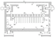
Fig. 1 is an overall structure diagram of the utility model.
FIG. 2 is a front view of the utility model
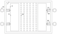
Fig. 3 is a top view of the protective shell in the utility model.
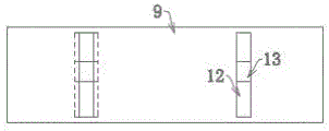
Fig. 4 is a front view of the rear side of the middle positioning plate of the utility model.
In the figure: 1-protective shell, 2-top cover, 3-placing plate, 4-upper cavity, 5-lower cavity, 6-rectangular hole, 7-movable block, 8-guide column, 9-positioning plate, 10-limiting plate, 11-first spring, 12-sliding groove, 13-sliding block, 14-pull rod, 15-pull ring, 16-through hole, 17-radiating fan, 18-radiating channel, 19-damping column, 20-supporting bottom plate, 21-rubber sucker, 22-protective pad, 23-radiating strip, 24-radiating fin, 25-fixing plate, 26-second spring, 27-cylindrical barrel, 28-moving plate, 29-damping spring and 30-moving rod.
Detailed Description
The present invention will be described in further detail below with reference to specific embodiments and with reference to the accompanying drawings.
The first embodiment is as follows: as shown in FIGS. 1 and 2, the protection device for a KVM switch includes a protection housing 1, a top cover 2 covering the top of the protection housing 1, and the top cover 2 directly connected to the top of the protection housing 1.
The inside of protecting crust 1 is provided with places board 3, places board 3 and the setting of protecting crust 1 integrated into one piece, places board 3 and cuts apart into last cavity 4 and cavity 5 with protecting crust 1, goes up the leading flank of cavity 4 and has seted up rectangular hole 6, sets up rectangular hole 6 and spills the jack and the button of KVM switch, makes things convenient for plug wire and switch KVM switch.
Place and install two movable blocks 7 on the board 3, wherein, the equal welded fastening in both sides installs the connecting axle around movable block 7, and movable block 7 is the spheroid, movable block 7 through the connecting axle with place and rotate between the board 3 and be connected.
Run through being provided with guide post 8 in the movable block 7, guide post 8 and the inner wall sliding connection of movable block 7, the top welded fastening of guide post 8 is connected with locating plate 9, and locating plate 9 is the bending plate, and two locating plates 9 are the symmetric distribution, and two locating plates 9 one side in opposite directions all bonds through glue has protection pad 22, and protection pad 22 adopts natural rubber to make, sets up protection pad 22, plays the guard action to the computer switch.
Bottom weld fixedly connected with limiting plate 10 of guide post 8, the surface cover of guide post 8 is equipped with first spring 11, first spring 11 is located between movable block 7 and the limiting plate 10, first spring 11's both ends respectively with movable block 7, limiting plate 10 adopts weld fixed connection, as shown in fig. 4, spout 12 has been seted up to the side that two locating plates 9 kept away from each other, the inside sliding connection of spout 12 has sliding block 13, sliding block 13's lateral surface articulates there is pull rod 14, pull rod 14 run through protective housing 1 the lateral wall and with pull ring 15 weld fixed connection, pull rod 14 and 1 sliding connection of protective housing.
Wherein, the fixed plate 25 of surface welding fixedly connected with of pull rod 14, and the fixed plate 25 lie in between sliding block 13 and protective housing 1, the surface cover of pull rod 14 is equipped with second spring 26, and second spring 26 lies in between fixed plate 25 and protective housing 1, and the both ends of second spring 26 adopt welded fastening to be connected with fixed plate 25, protective housing 1 respectively.
The working principle is as follows: the utility model discloses when using, at first open top cap 2, then stimulate pull ring 15, pull ring 15 can remove to 1 both sides of protecting crust, thereby can drive the motion of locating plate 9 through pull rod 14, locating plate 9 can make movable block 7 and place relative rotation between the board 3 through guide post 8 simultaneously, and then can make the interval increase between the locating plate 9, then place the computer switch at the top of placing board 3, second spring 26 promotes the fixed plate 25 motion when loosening pull ring 15, make the protection pad 22 on locating plate 9 surface laminate mutually with the computer switch, first spring 11's elastic restoring force promotes limiting plate 10 downstream after that, and then can press from both sides between locating plate 9 and the computer switch and press from both sides tightly fixedly, can play the effect of shock attenuation buffering simultaneously, avoid the computer switch to receive the vibrations damage.
As shown in fig. 3, a plurality of through holes 16 are uniformly formed in the placing plate 3, a heat dissipating fan 17 is installed on the left side wall of the lower cavity 5, the heat dissipating fan 17 is fixed on the side wall of the lower cavity 5 through screws, a heat dissipating passage 18 is formed in the right side wall of the lower cavity 5, the heat dissipating passage 18 is a plurality of heat dissipating passages 18, the heat dissipating passage 18 is obliquely arranged, one end of the heat dissipating passage 18 inside the protecting shell 1 is higher than one end of the protecting shell 1 outside, and external dust can be prevented from entering the lower cavity 5 through the heat dissipating passage 18. Through the through hole, the heat generated at the bottom of the computer switcher during operation can be conveniently dissipated, and through the arrangement of the cooling fan 17, the heat generated by the computer switcher can be discharged from the cooling channel 18, so that the computer switcher can be stably used for a long time.
The bottom of protective housing 1 is provided with shock-absorbing column 19, and when the device dropped or transported, shock-absorbing column 19 and the first spring 11 combined action can play certain cushioning effect, greatly reduced the vibrations striking that receives of KVM switch, can avoid the KVM switch to receive the damage.
The bottom surface of shock attenuation post 19 is provided with supporting baseplate 20, and rubber suction cup 21 is installed to supporting baseplate 20's bottom surface, and rubber suction cup 21 adopts prior art, and rubber suction cup 21's top has the screw rod through glue bonding, and rubber suction cup 21 passes through the screw rod to be connected in supporting baseplate 20's bottom surface, sets up rubber suction cup 21, can increase the device's stability with the firm absorption of the device on table surface.
Example two: further on the basis of above-mentioned embodiment, the bottom surface of placing board 3 is connected with a plurality of heat dissipation strips 23, heat dissipation strip 23 is gluing in the bottom surface of placing board 3 through the heat dissipation adhesive, heat dissipation strip 23 is two, two heat dissipation strips 23 are the symmetric distribution and are placing the bottom surface of board 3, the bottom welded connection of heat dissipation strip 23 has radiating fin 24, radiating fin 24's surface is scribbled and is equipped with heat conduction silicone grease, the heat that the KVM switch produced can be absorbed to heat dissipation strip 23, and transmit for radiating fin 24, set up like this and to concentrate on cavity 5 under with most heat that the KVM switch produced, be convenient for discharge the heat through radiator fan 17.
Example three: on the basis of the above embodiment, the shock absorbing column 19 includes the cylinder 27, the cylinder 27 penetrates through the bottom surface of the protective shell 1, the cylinder 27 and the bottom surface of the protective shell 1 are fixedly connected by welding, the movable plate 28 is slidably connected inside the cylinder 27, the top surface of the movable plate 28 is connected with the top surface inside the cylinder 27 through the shock absorbing spring 29, two ends of the shock absorbing spring 29 are respectively fixedly connected with the movable plate 28 and the cylinder 27 by welding, the top surface of the movable plate 28 is fixedly connected with the movable rod 30 by welding, and the movable rod 30 penetrates through the bottom surface of the cylinder 27 and is fixedly connected with the supporting bottom plate 20 by welding. The utility model discloses when the device fell or transported, can play certain cushioning effect through damping spring 29 and the common mating reaction of first spring 11, greatly reduced the vibrations striking that receives of KVM switch, can avoid the KVM switch to receive the damage.
In summary, the utility model can block the KVM switch through the protective shell, and avoid the KVM switch from direct collision; the heat dissipation fan can discharge the heat generated by the computer switcher, thereby ensuring the long-term stable use of the computer switcher; the shock absorption column and the first spring can play a certain buffering role, so that the shock impact on the computer switcher is greatly reduced, and the computer switcher can be prevented from being damaged; the rubber sucker is arranged, so that the device can be firmly adsorbed on the working table surface, and the stability of the device is improved.
Claims (7)
1. A protector for a computer switcher comprises a protective shell (1), wherein a top cover (2) covers the top of the protective shell (1), and the protector is characterized in that a placing plate (3) is arranged inside the protective shell (1), the protecting shell (1) is divided into an upper cavity (4) and a lower cavity (5) by the placing plate (3), a rectangular hole (6) is formed in the front side surface of the upper cavity (4), two movable blocks (7) are installed on the placing plate (3), guide columns (8) penetrate through the movable blocks (7), the guide columns (8) are slidably connected with the inner walls of the movable blocks (7), a positioning plate (9) is connected to the top ends of the guide columns (8), a limiting plate (10) is connected to the bottom ends of the guide columns (8), a first spring (11) is sleeved on the surface of the guide columns (8), and the first spring (11) is located between the movable blocks (7) and the limiting plate (10), two spout (12) have been seted up to the side of keeping away from each other of locating plate (9), spout (12) inside sliding connection has sliding block (13), the lateral surface of sliding block (13) articulates there is pull rod (14), pull rod (14) run through the lateral wall of protecting crust (1) and with pull ring (15) fixed connection, pull rod (14) with protecting crust (1) sliding connection, evenly be provided with a plurality of through-holes (16) on placing board (3), radiator fan (17) are installed to the left side wall of cavity (5) down, radiating passage (18) have been seted up to the right side wall of cavity (5) down, the bottom of protecting crust (1) is provided with shock absorber column (19), the bottom surface of shock absorber column (19) is provided with supporting baseplate (20), rubber suction cup (21) are installed to the bottom surface of supporting baseplate (20).
2. The protection device for KVM switch as claimed in claim 1, wherein said positioning plates (9) are folded plates, and two of said positioning plates (9) are symmetrically distributed, and a protection pad (22) is adhered to one side of each of said two positioning plates (9), and said protection pad (22) is made of natural rubber.
3. The protection device for the KVM switch according to claim 1, wherein a connecting shaft is fixedly installed on each of the front and rear sides of the movable block (7), and the movable block (7) is a sphere, and the movable block (7) is rotatably connected to the placing plate (3) through the connecting shaft.
4. The device as claimed in claim 1, wherein the bottom surface of the placement plate (3) is connected with a plurality of heat dissipation strips (23), the bottom of each heat dissipation strip (23) is fixedly connected with a heat dissipation fin (24), and the surface of each heat dissipation fin (24) is coated with heat conductive silicone grease.
5. The device as claimed in claim 1, wherein a fixing plate (25) is attached to a surface of the pull rod (14), and the fixing plate (25) is located between the sliding block (13) and the protective shell (1), and a second spring (26) is sleeved on the surface of the pull rod (14), and the second spring (26) is located between the fixing plate (25) and the protective shell (1).
6. The protection device for the KVM switch according to claim 1, wherein said shock absorbing column (19) comprises a cylindrical tube (27), said cylindrical tube (27) is disposed through the bottom surface of said housing (1), a moving plate (28) is slidably connected inside said cylindrical tube (27), a top surface of said moving plate (28) is connected to the top surface inside said cylindrical tube (27) through a shock absorbing spring (29), a moving rod (30) is connected to the top surface of said moving plate (28), and said moving rod (30) penetrates the bottom surface of said cylindrical tube (27) and is fixedly connected to said supporting bottom plate (20).
7. The apparatus as claimed in claim 1, wherein the heat dissipation channel (18) is disposed in a plurality of channels, and the heat dissipation channel (18) is disposed in an inclined manner and has an end located inside the protective housing (1) higher than an end located outside the protective housing (1).
Priority Applications (1)
| Application Number | Priority Date | Filing Date | Title |
|---|---|---|---|
| CN202120467836.8U CN214757236U (en) | 2021-03-04 | 2021-03-04 | Protection device for computer switcher |
Applications Claiming Priority (1)
| Application Number | Priority Date | Filing Date | Title |
|---|---|---|---|
| CN202120467836.8U CN214757236U (en) | 2021-03-04 | 2021-03-04 | Protection device for computer switcher |
Publications (1)
| Publication Number | Publication Date |
|---|---|
| CN214757236U true CN214757236U (en) | 2021-11-16 |
Family
ID=78591399
Family Applications (1)
| Application Number | Title | Priority Date | Filing Date |
|---|---|---|---|
| CN202120467836.8U Active CN214757236U (en) | 2021-03-04 | 2021-03-04 | Protection device for computer switcher |
Country Status (1)
| Country | Link |
|---|---|
| CN (1) | CN214757236U (en) |
-
2021
- 2021-03-04 CN CN202120467836.8U patent/CN214757236U/en active Active
Similar Documents
| Publication | Publication Date | Title |
|---|---|---|
| CN109388209A (en) | A kind of computer cabinet with shock-absorbing function | |
| CN209880406U (en) | Capacitor with shock-absorbing function | |
| CN215342842U (en) | New energy battery convenient to equipment | |
| CN208191006U (en) | A kind of new type corrosion resistant pcb board | |
| CN210804262U (en) | Hard disk mounting structure for computer | |
| CN209762985U (en) | Horizontal LED power | |
| CN209514520U (en) | An information processing device for geotechnical engineering monitoring | |
| CN209914372U (en) | Embedded control panel protection device | |
| CN214177145U (en) | Multifunctional power adapter | |
| CN212062082U (en) | Shock attenuation heat dissipation shell of planar transformer | |
| CN209625791U (en) | A kind of hard disc of computer mounting structure | |
| CN115407847A (en) | Shock attenuation heat dissipation type computer hard disk protection device | |
| CN221264062U (en) | Circuit board with buffering shock-absorbing structure | |
| CN219163388U (en) | A fast recovery diode module | |
| CN216650258U (en) | Photon time delayer | |
| CN222483543U (en) | A protective device for new energy vehicle battery | |
| CN215450897U (en) | Novel protection device for solid state disk of computer | |
| CN220796296U (en) | Computer hard disk with buffer function | |
| CN213586101U (en) | Router shell | |
| CN219933529U (en) | Camera module support structure | |
| CN206545916U (en) | A driving power protection device | |
| CN223182164U (en) | Router protection device | |
| CN211231419U (en) | Buffer device on silicon-aluminum alloy box body | |
| CN223246584U (en) | Communication receiving and dispatching hard board with protection function | |
| CN211297121U (en) | High-efficient heat dissipation flexible circuit board |
Legal Events
| Date | Code | Title | Description |
|---|---|---|---|
| GR01 | Patent grant | ||
| GR01 | Patent grant |