Novel ceiling lamp convenient to install and replace
Technical Field
The utility model relates to a ceiling lamp technical field specifically is a novel ceiling lamp is changed in easy to assemble.
Background
When the ceiling lamp is installed, the ceiling lamp needs to be hoisted by matching with a hanging bracket and the like, when the ceiling lamp is assembled by the hanging bracket, the operation is inconvenient, and when the ceiling lamp is replaced correspondingly, the lamp holder is not convenient to disassemble and replace from the lamp bracket, so that inconvenience is brought to the installation and replacement of the ceiling lamp.
SUMMERY OF THE UTILITY MODEL
An object of the utility model is to provide a novel ceiling lamp is changed in easy to assemble possesses and is convenient for use the ceiling lamp equipment to when needing to change the ceiling lamp, direct to the lamp holder with cooperate the nonrust steel sheet of installation dismantle the lamp holder can, improve the advantage of changing the convenience to the ceiling lamp installation, solved the gallows and assembled the operation inconvenience to the ceiling lamp, and when corresponding the ceiling lamp and change, be not convenient for dismantle the change from the lighting fixture with the lamp holder, change the problem that brings inconvenience for the installation of ceiling lamp.
In order to achieve the above object, the utility model provides a following technical scheme: a novel ceiling lamp convenient to install and replace comprises a stainless steel supporting sheet, a stainless steel installing sheet, nuts, screws, a lamp holder and a crystal structure matched with the lamp holder, wherein installing hole positions are arranged on the stainless steel supporting sheet at equal intervals, and two ends of the stainless steel installing sheet are provided with a second installing hole position;
the utility model discloses a lamp holder, including lamp holder, screw, mounting hole site, two, lamp holders, the inside heat dissipation post that is equipped with of lamp holder to correspond the heat dissipation post and be equipped with the lamp plate, and be equipped with the light source structure through the surface of lamp plate, the center that the lamp plate corresponds the lamp holder is equipped with electrically conductive circle, the nut adopts the setting of double-end internal thread structure, inside the lamp holder was located to the nut, the end of screw passes the center of mounting hole site, mounting hole site two, lamp holder in proper order and the terminal spiro union of nut, the installation end of crystal structure be equipped with nut complex double-screw bolt, the other end spiro union of double-screw bolt and nut is passed through to the installation end of crystal structure.
Furthermore, the stainless steel mounting pieces are provided with a plurality of groups according to the assembly requirements of the ceiling lamp.
Furthermore, the periphery of the lamp holder is provided with light holes corresponding to the light source structure.
Furthermore, an insulating rubber sleeve is sleeved outside the screw and is arranged in a contact mode with the center of the lamp holder through the insulating rubber sleeve and the mounting hole position, the mounting hole position II and the center of the lamp holder.
Furthermore, the crystal structure is arranged in any shape according to the requirement of the ceiling lamp.
Compared with the prior art, the beneficial effects of the utility model are as follows:
1. the utility model discloses a stainless steel installation piece cooperation stainless steel backing sheet is installed to the lamp holder to install through nut cooperation screw and stainless steel installation piece inside the lamp holder, the terminal cooperation spiro union of quartzy structure through double-screw bolt and nut improves the convenience of lamp holder cooperation ceiling lamp installation, and is convenient for dismantle the change to lamp holder and quartzy structure according to the use needs, improves convenient to use;
the lamp holder is located inside through the heat dissipation post to the lamp plate, directly derives the heat dissipation to the heat that the lamp plate operation produced through the heat dissipation post, radiating effect when improving the lamp plate operation.
Drawings
FIG. 1 is a schematic view of the overall structure of the present invention;
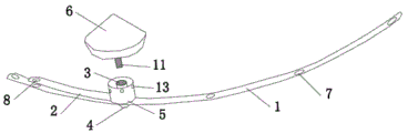
FIG. 2 is a schematic view of the crystal structure and the lamp holder dismounting structure of the present invention;
FIG. 3 is a schematic view of the installation structure of the present invention;
fig. 4 is a schematic view of the cross-sectional structure of the lamp panel and the lamp cap in cooperation installation of the present invention;
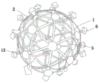
fig. 5 is a schematic diagram of the structure of the finished product of the present invention.
In the figure: 1. a stainless steel support sheet; 2. a stainless steel mounting plate; 3. a nut; 4. a screw; 5. a lamp cap; 6. a crystal structure; 7. mounting hole sites; 8. mounting a second hole site; 9. a heat-dissipating column; 10. a light source structure; 11. a stud; 12. a light-transmitting hole; 13. insulating rubber sleeves; 14. a lamp panel; 15. and a conductive ring.
Detailed Description
The technical solutions in the embodiments of the present invention will be described clearly and completely with reference to the accompanying drawings in the embodiments of the present invention, and it is obvious that the described embodiments are only some embodiments of the present invention, not all embodiments. Based on the embodiments in the present invention, all other embodiments obtained by a person skilled in the art without creative work belong to the protection scope of the present invention.
Referring to fig. 1-5, a novel ceiling lamp convenient to mount and replace comprises a stainless steel support sheet 1, a stainless steel mounting sheet 2, a nut 3, a screw 4, a lamp holder 5 and a crystal structure 6 matched with the lamp holder 5, wherein the crystal structure 6 can be an ornament of any shape, mounting hole sites 7 are equidistantly arranged on the stainless steel support sheet 1, and mounting hole sites two 8 are arranged at two ends of the stainless steel mounting sheet 2;
the inside heat dissipation post 9 that is equipped with of lamp holder 5 to correspond heat dissipation post 9 and be equipped with lamp plate 14, and be equipped with light source structure 10 through the surface of lamp plate 14, the center that lamp plate 14 corresponds lamp holder 5 is equipped with conductive loop 15, and conductive loop is positive electrode electricity, back conductive negative pole electricity for openly leading, can not produce the problem of short circuit when making lamp plate and power be connected, nut 3 adopts the setting of double-end internal thread structure, inside lamp holder 5 was located to nut 3, the end of screw 4 passes the center of installation hole site 7, two 8 of installation hole sites, lamp holder 5 and the terminal spiro union of nut 3 in proper order, the installation end of crystal structure 6 is equipped with and nut 3 complex double-screw bolt 11, the other end spiro union of double-screw bolt 11 and nut 3 is passed through to the installation end of crystal structure 6.
Specifically, the stainless steel mounting pieces 2 are provided with a plurality of groups according to the assembly requirements of the ceiling lamp.
Specifically, the periphery of the lamp cap 5 is provided with a light hole 12 corresponding to the light source structure 10.
Specifically, the outer part of the screw 4 is sleeved with an insulating rubber sleeve 13, and the insulating rubber sleeve 13 is arranged in contact with the mounting hole 7, the second mounting hole 8 and the center of the lamp holder 5.
Specifically, the crystal structure 6 is arranged in any shape according to the requirement of the ceiling lamp.
During assembly, after the insulating rubber sleeve 13 is sleeved outside the screw 4, the tail end of the screw 4 penetrates through the back surface of the stainless steel support sheet 1 and penetrates through the mounting hole position 7 and the mounting hole position two 8 of the stainless steel mounting sheet 2, the lamp plate 14 is mounted inside the lamp holder 5, the back surface of the lamp plate 14 is contacted with the tail end of the heat dissipation column 9, the nut 3 is placed inside the lamp holder 5 corresponding to the center of the lamp plate 14, the tail end of the screw 4 penetrates through the mounting end of the lamp holder 5 and is in threaded connection with the nut 3, the lamp holder 5 is fixed on the stainless steel mounting sheet 2, the crystal structure 6 is in threaded connection with the tail end of the nut 3 through the stud 11, assembly of a ceiling lamp is completed, and when the lamp holder 5 is replaced or disassembled, the lamp holder 5 is timely disassembled by reversely screwing the screw 4 and the nut 3;
because lamp plate 14 is installed inside lamp holder 5 through heat dissipation post 9, when 14 operation light source structures 10 of lamp plate produced light, heat dissipation that heat dissipation post 9 produced 14 operations of lamp plate dispels the heat, improves 14 operating stability of lamp plate and life.
In summary, the following steps: through the installation of stainless steel installation piece 2 cooperation stainless steel backing sheet 1 to lamp holder 5 to at the inside installation of lamp holder 5 through 3 cooperation screws 4 of nut and stainless steel installation piece 2, quartzy structure 6 passes through the terminal cooperation spiro union of double-screw bolt 11 with nut 3, improves the convenience of lamp holder 5 cooperation ceiling lamp installation, and is convenient for dismantle the change to lamp holder 5 and quartzy structure 6 according to the use needs, improves convenient to use nature.