CN214739737U - Lifting scaffold closes bearing structure in bottom - Google Patents
Lifting scaffold closes bearing structure in bottom Download PDFInfo
- Publication number
- CN214739737U CN214739737U CN202121369150.1U CN202121369150U CN214739737U CN 214739737 U CN214739737 U CN 214739737U CN 202121369150 U CN202121369150 U CN 202121369150U CN 214739737 U CN214739737 U CN 214739737U
- Authority
- CN
- China
- Prior art keywords
- leg
- rotating
- cavity
- supporting leg
- scaffold
- Prior art date
- Legal status (The legal status is an assumption and is not a legal conclusion. Google has not performed a legal analysis and makes no representation as to the accuracy of the status listed.)
- Active
Links
- 230000008093 supporting effect Effects 0.000 claims abstract description 54
- 235000017166 Bambusa arundinacea Nutrition 0.000 claims abstract 4
- 235000017491 Bambusa tulda Nutrition 0.000 claims abstract 4
- 241001330002 Bambuseae Species 0.000 claims abstract 4
- 235000015334 Phyllostachys viridis Nutrition 0.000 claims abstract 4
- 239000011425 bamboo Substances 0.000 claims abstract 4
- 230000005540 biological transmission Effects 0.000 claims description 3
- 244000309464 bull Species 0.000 abstract description 8
- 230000000994 depressogenic effect Effects 0.000 abstract 1
- 230000000694 effects Effects 0.000 description 3
- 238000010276 construction Methods 0.000 description 2
- 238000000034 method Methods 0.000 description 2
- 238000009435 building construction Methods 0.000 description 1
- 238000004891 communication Methods 0.000 description 1
- 230000007547 defect Effects 0.000 description 1
- 238000012986 modification Methods 0.000 description 1
- 230000004048 modification Effects 0.000 description 1
Images



Landscapes
- Movable Scaffolding (AREA)
Abstract
The utility model discloses a lift scaffold seals bearing structure in bottom, concretely relates to scaffold frame field, including the I-shaped piece, the fixed section of thick bamboo of department fixedly connected with in the middle of the I-shaped piece bottom, fixed section of thick bamboo inner chamber is equipped with the foot rest leg, the through-hole has been seted up on the I-shaped piece, and foot rest leg top runs through the through-hole inner chamber, the I-shaped piece left and right sides depressed part all is equipped with the commentaries on classics board, the equal fixedly connected with fixed block of bottom department is close to with the I-shaped piece left and right sides to one side that the commentaries on classics board was kept away from mutually. The utility model discloses a slider drives the dead lever motion, and the dead lever drives first supporting leg and rotates, can have the support of left right direction to the scaffold leg, and the bull stick that the hand wheel drove to be located the right side rotates, drives through first sheave, belt and second sheave and is located left bull stick and rotates, drives two bull sticks when two bull sticks rotate, and the bull stick drives the second supporting leg and rotates, has the support of fore-and-aft direction to the scaffold leg, can have the supporting effect of a plurality of directions to the scaffold leg.
Description
Technical Field
The utility model relates to a scaffold technical field, more specifically say, the utility model relates to a lifting foot hand rack bottom seals bearing structure.
Background
The scaffold is a working platform which is erected for ensuring that each construction process is carried out smoothly, is a support platform which is erected for facilitating the operation of constructors and construction projects, can solve the problem of material transportation in the vertical and horizontal directions, is widely applied to the field of building construction, and is an important working platform.
The scaffold frame need support the scaffold leg when using fixedly, prevents that it from taking place to empty and lead to dangerous emergence, and current most bearing structure only has the supporting effect of a direction, and the supporting effect is not good, and the practicality is poor.
SUMMERY OF THE UTILITY MODEL
In order to overcome prior art's above-mentioned defect, the embodiment of the utility model provides a lift scaffold closes bearing structure bottom, drive the dead lever motion through the slider, the dead lever drives first supporting leg and rotates, can have the support of direction about to the scaffold leg, the bull stick that the hand wheel drive is located the right side rotates, through first sheave, belt and second sheave drive are located left bull stick and rotate, two bull sticks drive two commentaries on classics boards when rotating, the commentaries on classics board drives the rotation of second supporting leg, there is the support of fore-and-aft direction to the scaffold leg, can have the supporting effect of a plurality of directions to the scaffold leg, in order to solve the problem that proposes among the above-mentioned background art.
In order to achieve the above object, the utility model provides a following technical scheme: a bottom closed supporting structure of a lifting scaffold comprises an I-shaped block, wherein a fixed cylinder is fixedly connected to the middle of the bottom of the I-shaped block, a scaffold leg is arranged in an inner cavity of the fixed cylinder, a through hole is formed in the I-shaped block, the top ends of the scaffold leg penetrate through the inner cavity of the through hole, rotating plates are arranged at the concave positions of the left side and the right side of the I-shaped block, fixed blocks are fixedly connected to the far side of each rotating plate and the positions, close to the bottom, of the left side and the right side of the I-shaped block, the front sides of the four fixed blocks are movably connected with first rotating shafts, a second supporting leg and a first supporting leg are respectively sleeved on each first rotating shaft of an upper group and a lower group, a cavity is formed in the I-shaped block, two rotating rods are arranged in the cavity, the top ends of the two rotating rods penetrate through the top of the cavity and are movably connected with the top of the inner cavity at the two sides of the I-shaped block, the two rotating rods respectively penetrate through the adjacent rotating plates and are movably connected with the top of the concave positions at the two sides of the I-shaped block, the bottom end of the rotating rod positioned on the left side is movably connected with the bottom of the cavity, a second grooved wheel and a first grooved wheel are respectively sleeved on the two rotating rods positioned on the left side and the right side, a belt is arranged between the first grooved wheel and the second grooved wheel, and the first grooved wheel is in transmission connection with the second grooved wheel through the belt.
In a preferred embodiment, a non-slip mat is fixedly connected to the bottom end of the fixed cylinder.
In a preferred embodiment, supporting legs are arranged below the two first supporting legs and the two second supporting legs, a second rotating shaft is inserted into each of the four supporting legs, and the rear ends of the four second rotating shafts are movably connected with the front sides of the adjacent first supporting legs or the adjacent second supporting legs close to the bottom ends respectively.
In a preferred embodiment, the bottom end of the rotating rod on the right side penetrates through the bottom of the cavity and is movably connected with the cavity, and the bottom end of the rotating rod on the right side is fixedly connected with a hand-operated wheel.
In a preferred embodiment, sliding grooves are formed in the left side and the right side of the fixed cylinder, sliding blocks are connected in the two sliding grooves in a sliding mode, third rotating shafts are inserted into the two sliding blocks, fixing rods are movably connected to the rear ends of the two third rotating shafts, and one ends, far away from the sliding blocks, of the two fixing rods are hinged to the adjacent first supporting legs respectively.
In a preferred embodiment, a plurality of blind holes are formed in adjacent sides of the two sliding grooves, the two sliding blocks are respectively inserted with a T-shaped rod, and adjacent ends of the two T-shaped rods are respectively inserted into an inner cavity of one of the blind holes.
In a preferred embodiment, a plurality of limiting holes are formed in the rear side of each leg, a rectangular opening is formed in the rear side of each fixed cylinder close to the top, a limiting rod is arranged in each rectangular opening, an L-shaped rod is fixedly connected to the rear end of each limiting rod, and the front side of each L-shaped rod is hinged to the rear side of each fixed cylinder close to the bottom.
The utility model discloses a technological effect and advantage:
1. the sliding block drives the fixed rod to move, the fixed rod drives the first supporting leg to rotate until two supporting legs on the first supporting leg are contacted with the ground, the left and right supporting legs can be supported, the hand-operated wheel drives the rotating rod on the right side to rotate, the rotating rod on the left side is driven to rotate through the first grooved wheel, the belt and the second grooved wheel, the two rotating rods drive the two rotating plates when rotating, the two rotating plates drive the second supporting leg to rotate, and the supporting legs can be supported in the front and back directions.
2. Through pressing L type pole downwards, L type pole drives the gag lever post and breaks away from spacing hole, can adjust the height of scaffold leg this moment, presses the gag lever post again and injects spacing downthehole, carries on spacingly to it, compares with prior art, the height of the whole scaffold frame of regulation that can be very convenient has increased its application scope, excellent in use effect, and the practicality is strong.
Drawings
Fig. 1 is a perspective view of the present invention.
Fig. 2 is a schematic view of the overall structure of the present invention.
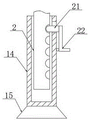
Fig. 3 is a right side sectional view of the fixing cylinder of the present invention.
Fig. 4 is a top view of the rotating plate of the present invention.
The reference signs are: 1. an I-shaped block; 2. a foot rest leg; 3. rotating the plate; 4. a fixed block; 5. a first rotating shaft; 6. a first sheave; 7. a hand-operated wheel; 8. a second rotating shaft; 9. supporting legs; 10. fixing the rod; 11. a first support leg; 12. a T-shaped rod; 13. a rotating rod; 14. a fixed cylinder; 15. a non-slip mat; 16. a slider; 17. a third rotating shaft; 18. a second support leg; 19. a belt; 20. a second sheave; 21. a limiting rod; 22. an L-shaped rod.
Detailed Description
The technical solutions in the embodiments of the present invention will be described clearly and completely with reference to the accompanying drawings in the embodiments of the present invention, and it is obvious that the described embodiments are only some embodiments of the present invention, not all embodiments. Based on the embodiments in the present invention, all other embodiments obtained by a person skilled in the art without creative work belong to the protection scope of the present invention.
As shown in the attached figures 1-4, the bottom closed supporting structure of the lifting scaffold comprises an I-shaped block 1, a fixed cylinder 14 is fixedly connected to the middle of the bottom of the I-shaped block 1, a scaffold leg 2 is arranged in the inner cavity of the fixed cylinder 14, a through hole is arranged on the I-shaped block 1, the top end of the scaffold leg 2 penetrates through the inner cavity of the through hole, rotating plates 3 are arranged at the sunken positions of the left side and the right side of the I-shaped block 1, the far side of each rotating plate 3 and the position of the left side and the right side of the I-shaped block 1, which are close to the bottom, are fixedly connected with fixed blocks 4, first rotating shafts 5 are movably connected with the front sides of the four fixed blocks 4, a second supporting leg 18 and a first supporting leg 11 are respectively sleeved on each of the two groups of upper and lower first rotating shafts 5, a cavity is arranged on the I-shaped block 1, two rotating rods 13 are arranged in the cavity, and the top ends of the two rotating rods 13 penetrate through the top of the cavity and are movably connected with the cavity, the top ends of the two rotating rods 13 respectively penetrate through the adjacent rotating plates 3 and are movably connected with the tops of the inner cavities of the concave parts at the two sides of the I-shaped block 1, the bottom end of the rotating rod 13 positioned at the left side is movably connected with the bottom of the cavity, the two rotating rods 13 positioned at the left side and the right side are respectively sleeved with a second grooved pulley 20 and a first grooved pulley 6, a belt 19 is arranged between the first grooved pulley 6 and the second grooved pulley 20, and the first grooved pulley 6 is in transmission connection with the second grooved pulley 20 through the belt 19.
As shown in the attached figure 1, the bottom end of the fixed cylinder 14 is fixedly connected with a non-slip mat 15, so that the fixed cylinder 14 is prevented from sliding, and the supporting effect is improved.
As shown in the attached drawing 2, the supporting legs 9 are arranged below the two first supporting legs 11 and the two second supporting legs 18, the second rotating shafts 8 are inserted into the four supporting legs 9, the rear ends of the four second rotating shafts 8 are movably connected with the front sides of the adjacent first supporting legs 11 or the adjacent second supporting legs 18 close to the bottom ends respectively, the sliding of the first supporting legs 11 and the second supporting legs 18 is prevented, and the stability of the device is improved.
As shown in fig. 2, the bottom end of the right rotating rod 13 penetrates through the bottom of the cavity and is movably connected with the cavity, and the bottom end of the right rotating rod 13 is fixedly connected with the hand-operated wheel 7, so that the rotating rod 13 can be conveniently rotated.
As shown in fig. 2, the sliding grooves are formed in the left side and the right side of the fixed cylinder 14, the sliding blocks 16 are connected in the two sliding grooves in a sliding mode, the third rotating shafts 17 are inserted into the two sliding blocks 16, the rear ends of the two third rotating shafts 17 are movably connected with the fixing rods 10, and one ends, far away from the sliding blocks 16, of the two fixing rods 10 are hinged to the adjacent first supporting legs 11 respectively, so that the supporting effect of the device is improved conveniently.
As shown in fig. 2, a plurality of blind holes are formed in adjacent sides of the two sliding grooves, the two sliding blocks 16 are respectively inserted with the T-shaped rods 12, and adjacent ends of the two T-shaped rods 12 are respectively inserted into an inner cavity of one of the blind holes, so that the angle of the first supporting leg 11 can be changed.
As shown in the attached drawing 3, a plurality of limiting holes are formed in the rear side of each leg 2, a rectangular opening is formed in the rear side of each fixing barrel 14 close to the top, a limiting rod 21 is arranged in each rectangular opening, the rear end of each limiting rod 21 is fixedly connected with an L-shaped rod 22, the front side of each L-shaped rod 22 is hinged to the rear side of each fixing barrel 14 close to the bottom, and the legs 2 are convenient to lift.
The utility model discloses the theory of operation: when the utility model is used, firstly, the device is placed at a designated position, two T-shaped rods 12 are pulled outwards to be separated from a blind hole, a sliding block 16 slides in a chute, the sliding block 16 drives a fixed rod 10 to move, the fixed rod 10 drives a first supporting leg 11 to rotate by taking a first rotating shaft 5 as a center until two supporting legs 9 on the first supporting leg 11 are contacted with the ground, the T-shaped rods 12 are inserted into the blind hole for limiting, the bracket legs 2 can be supported in the left and right directions, a hand wheel 7 is rotated, the hand wheel 7 drives a rotating rod 13 positioned on the right side to rotate, the rotating rod 13 positioned on the right side drives a rotating rod 13 positioned on the left side to rotate through a first grooved wheel 6, a belt 19 and a second grooved wheel 20, two rotating plates 3 are driven when the two rotating rods 13 rotate, the two rotating plates 3 drive the second supporting legs 18 to rotate, the bracket legs 2 can be supported in the front and back directions, prevent that it from taking place to empty, improved the stability of scaffold when in the time, when needs highly adjust 2 of scaffold leg, press L type pole 22 downwards, L type pole 22 drives gag lever post 21 and breaks away from spacing hole, can adjust 2 of scaffold leg's height this moment, press again and press gag lever post 21 and inject spacing downthehole, spacing to it, easy operation, excellent in use effect.
The points to be finally explained are: first, in the description of the present application, it should be noted that, unless otherwise specified and limited, the terms "mounted," "connected," and "connected" should be understood broadly, and may be a mechanical connection or an electrical connection, or a communication between two elements, and may be a direct connection, and "upper," "lower," "left," and "right" are only used to indicate a relative positional relationship, and when the absolute position of the object to be described is changed, the relative positional relationship may be changed;
secondly, the method comprises the following steps: in the drawings of the disclosed embodiments of the present invention, only the structures related to the disclosed embodiments are referred to, and other structures can refer to the common design, and under the condition of no conflict, the same embodiment and different embodiments of the present invention can be combined with each other;
and finally: the above description is only for the preferred embodiment of the present invention and should not be taken as limiting the invention, and any modifications, equivalent replacements, improvements, etc. made within the spirit and principle of the present invention should be included in the protection scope of the present invention.
Claims (7)
1. The utility model provides a lift scaffold bottom closed support structure, includes I-shaped piece (1), its characterized in that: the middle of the bottom of the I-shaped block (1) is fixedly connected with a fixed cylinder (14), the inner cavity of the fixed cylinder (14) is provided with foot rest legs (2), the I-shaped block (1) is provided with a through hole, the top end of each foot rest leg (2) penetrates through the inner cavity of the through hole, sunken parts on the left side and the right side of the I-shaped block (1) are respectively provided with a rotating plate (3), one side, far away from the rotating plates (3), of the rotating plates and the left side and the right side of the I-shaped block (1) are respectively and fixedly connected with a fixed block (4) near the bottom, the front sides of the four fixed blocks (4) are respectively and movably connected with a first rotating shaft (5), every two rotating shafts (5) of the upper group and the lower group are respectively sleeved with a second supporting leg (18) and a first supporting leg (11), the I-shaped block (1) is provided with a cavity, two rotating rods (13) are arranged in the cavity, and the top ends of the rotating rods (13) all penetrate through the top of the cavity and are movably connected with the cavity, the top ends of the two rotating rods (13) penetrate through the adjacent rotating plates (3) respectively and are movably connected with the tops of the inner cavities of the concave parts of the two sides of the I-shaped block (1), the bottom ends of the rotating rods (13) positioned on the left side are movably connected with the bottom of the cavity, the two rotating rods (13) positioned on the left side and the right side are respectively sleeved with a second grooved pulley (20) and a first grooved pulley (6), a belt (19) is arranged between the first grooved pulley (6) and the second grooved pulley (20), and the first grooved pulley (6) is in transmission connection with the second grooved pulley (20) through the belt (19).
2. The closed bottom support structure of a lifting scaffold according to claim 1, wherein: the bottom end of the fixed cylinder (14) is fixedly connected with an anti-skid pad (15).
3. The closed bottom support structure of a lifting scaffold according to claim 1, wherein: two first supporting leg (11) and two second supporting leg (18) below all is equipped with supporting legs (9), four all peg graft on supporting legs (9) and have second pivot (8), four second pivot (8) rear end is close to bottom department swing joint with adjacent first supporting leg (11) or second supporting leg (18) front side respectively.
4. The closed bottom support structure of a lifting scaffold according to claim 1, wherein: the bottom end of the rotating rod (13) on the right side penetrates through the bottom of the cavity and is movably connected with the cavity, and the bottom end of the rotating rod (13) on the right side is fixedly connected with a hand-operated wheel (7).
5. The closed bottom support structure of a lifting scaffold according to claim 1, wherein: the fixed cylinder (14) left and right sides has all seted up the spout, two equal sliding connection has slider (16) in the spout, two all peg graft on slider (16) has third pivot (17), two equal swing joint in third pivot (17) rear end has dead lever (10), two the one end that slider (16) were kept away from in dead lever (10) is articulated with adjacent first supporting leg (11) respectively.
6. The closed bottom supporting structure of a lifting scaffold according to claim 5, wherein: a plurality of blind holes are formed in one adjacent side of each of the two sliding grooves, T-shaped rods (12) are inserted into the two sliding blocks (16), and the adjacent ends of the two T-shaped rods (12) are inserted into the inner cavity of one of the blind holes respectively.
7. The closed bottom support structure of a lifting scaffold according to claim 1, wherein: the utility model discloses a leg fixing device, including scaffold leg (2), fixed section of thick bamboo (14), gag lever post (21) rear end fixedly connected with L type pole (22), L type pole (22) front side is close to bottom department and articulates with fixed section of thick bamboo (14) rear side.
Priority Applications (1)
| Application Number | Priority Date | Filing Date | Title |
|---|---|---|---|
| CN202121369150.1U CN214739737U (en) | 2021-06-21 | 2021-06-21 | Lifting scaffold closes bearing structure in bottom |
Applications Claiming Priority (1)
| Application Number | Priority Date | Filing Date | Title |
|---|---|---|---|
| CN202121369150.1U CN214739737U (en) | 2021-06-21 | 2021-06-21 | Lifting scaffold closes bearing structure in bottom |
Publications (1)
| Publication Number | Publication Date |
|---|---|
| CN214739737U true CN214739737U (en) | 2021-11-16 |
Family
ID=78630485
Family Applications (1)
| Application Number | Title | Priority Date | Filing Date |
|---|---|---|---|
| CN202121369150.1U Active CN214739737U (en) | 2021-06-21 | 2021-06-21 | Lifting scaffold closes bearing structure in bottom |
Country Status (1)
| Country | Link |
|---|---|
| CN (1) | CN214739737U (en) |
-
2021
- 2021-06-21 CN CN202121369150.1U patent/CN214739737U/en active Active
Similar Documents
| Publication | Publication Date | Title |
|---|---|---|
| CN216239615U (en) | Assembled scaffold for building construction | |
| CN209942277U (en) | Supporting device for mounting aluminum alloy template | |
| CN111186789B (en) | Promote handling device with adjustable angle that construction used | |
| CN213478186U (en) | High stability double ladder for building site | |
| CN110902616B (en) | Platform driving hydraulic device for engineering | |
| CN213356821U (en) | Steel structure supporting table | |
| CN217794463U (en) | Street machine grapple machine convenient to remove | |
| CN215167819U (en) | Movable scaffold | |
| CN210975131U (en) | Computer embroidery machine frame of transportation can be dismantled in taking precautions against earthquakes | |
| CN211776383U (en) | Enclose fender convenient to remove | |
| CN111962401B (en) | Drive device for climbing formwork | |
| CN211689963U (en) | An elevated platform for bridge construction work | |
| CN211548665U (en) | Building installation supporting platform | |
| CN213477574U (en) | Movable ascending frame | |
| CN214938859U (en) | Portable railway engineering steel rail line crossing device | |
| CN220788001U (en) | Anti-falling protection hanging basket | |
| CN221500474U (en) | Rotary lifting plate | |
| CN222042522U (en) | A construction lifting platform | |
| CN218375085U (en) | Crane for interior decoration | |
| CN218318515U (en) | Container underframe structure | |
| CN110497365A (en) | A kind of multifunctional solution casting die maintenance platform | |
| CN220828020U (en) | Interior decoration scaffold convenient to height-adjusting | |
| CN223779190U (en) | Interlocking block soaking maintenance device | |
| CN211276992U (en) | Complete machine mechanism of mobile laser marking equipment | |
| CN216429165U (en) | Steel frame structure for temporary stage construction |
Legal Events
| Date | Code | Title | Description |
|---|---|---|---|
| GR01 | Patent grant | ||
| GR01 | Patent grant |