CN214721232U - Thread following manufacturing device - Google Patents
Thread following manufacturing device Download PDFInfo
- Publication number
- CN214721232U CN214721232U CN202120824714.XU CN202120824714U CN214721232U CN 214721232 U CN214721232 U CN 214721232U CN 202120824714 U CN202120824714 U CN 202120824714U CN 214721232 U CN214721232 U CN 214721232U
- Authority
- CN
- China
- Prior art keywords
- thread
- following
- sleeve
- screw thread
- tail handle
- Prior art date
- Legal status (The legal status is an assumption and is not a legal conclusion. Google has not performed a legal analysis and makes no representation as to the accuracy of the status listed.)
- Active
Links
Images






Landscapes
- Forging (AREA)
Abstract
The utility model discloses a thread following manufacturing device, which comprises a tail handle, a following sleeve and a thread tapping part, wherein the following sleeve is sleeved on the tail handle in a sliding way, and the free end of the following sleeve is detachably provided with the thread tapping part; the tail handle is vertically provided with an anti-rotation pin, the following sleeve is correspondingly provided with a waist-shaped groove, and the anti-rotation pin is connected with the waist-shaped groove in a sliding mode. The utility model discloses a lead the cover to move ahead along with following by the lead angle that processing screw thread itself has, eliminated because the atress when the manual tapping is uneven, the guide is inconvenient, processing is intermittent, the profile of tooth defects such as not just, make the course of working of screw thread steady, continuous, the screw thread quality can improve, simultaneously, has reduced operation intensity, has improved machining efficiency.
Description
Technical Field
The utility model belongs to the technical field of screw thread making devices, concretely relates to making devices is followed to screw thread.
Background
In machining, we often encounter some external thread and internal thread workpiece machining, and the common methods are: the processing method comprises the following steps of moving a die frame plate, cutting a threading tool, cutting a thread milling cutter, rolling threads, tapping a screw tap and the like, the required cost of different processing methods is different, if a product can meet the requirement, aiming at internal thread processing, the simple tapping method is the lowest cost, and the tapping method by using the screw tap has the problems that the quality and the efficiency of the internal thread cannot be effectively guaranteed due to the fact that the threads are tapped manually, and the defects that the processed threads are inclined, the tooth forms are not correct and the like are often caused. Aiming at the processing of the external thread, the simple method of moving the die holder plate is the lowest cost, and the problem of moving the die holder plate is that the quality and the efficiency of the external thread cannot be effectively ensured because the thread is manufactured by the plate, and the defects of skew, irregular tooth form and the like of the processed thread are often caused.
SUMMERY OF THE UTILITY MODEL
An object of the utility model is to provide a making devices is followed to screw thread aims at improving thread machining quality and efficiency. The utility model discloses a lead the cover to move ahead along with following by the lead angle that processing screw thread itself has, eliminated because stress is uneven when the hand work screw thread, the guide is inconvenient, processing is intermittent, the profile of tooth defects such as not just, makes the course of working of screw thread steady, continuous, and the screw thread quality can improve, simultaneously, has reduced operation intensity, has improved machining efficiency.
The utility model discloses mainly realize through following technical scheme:
a thread following manufacturing device comprises a tail handle, a following sleeve and a thread tapping part, wherein the following sleeve is slidably sleeved on the tail handle, and the free end of the following sleeve is detachably provided with the thread manufacturing part; the tail handle is vertically provided with an anti-rotation pin, the following sleeve is correspondingly provided with a waist-shaped groove, and the anti-rotation pin is connected with the waist-shaped groove in a sliding mode. The anti-rotation pin can prevent the following sleeve from rotating relative to the tail handle.
The utility model discloses in the use, at first fix the caudal peduncle at lathe tailstock or drilling machine main shaft taper hole, attack the portion of attacking the screw thread and fix and follow and sheathe in, when starting the main shaft rotation, it is rotatory to a direction with the caudal peduncle, at this moment, follow the cover and attack the portion of attacking the screw thread and move forward simultaneously and carry out the screw thread preparation, process to set length after, it is rotatory to opposite direction with the main shaft, at this moment, the caudal peduncle is rotatory to opposite direction, follow the cover and withdraw from backward simultaneously with the portion of attacking the screw thread and break away from the work terminal surface, accomplish thread machining.
In order to realize better the utility model discloses, furtherly, the free end of following the cover corresponds screw thread preparation portion and is provided with the step hole, and follows one side of cover and be provided with set screw perpendicularly, set screw stretch into the step hole and with the fixed butt of one end of screw thread preparation portion. The following sleeve is provided with a mounting hole corresponding to the tail handle, plays a role in centering when the thread is manufactured, and moves synchronously along with the thread manufacturing part due to the positioning of the positioning screw when the thread is processed.
In order to better realize the utility model discloses, furtherly, the other end of following the cover corresponds the caudal peduncle and is provided with the mounting hole, and corresponds on the lateral wall of mounting hole and be provided with waist type groove.
In order to better realize the utility model discloses, further, screw thread producing part is screw tap or die.
The utility model discloses in the use, to internal screw thread processing, realize internal screw thread processing through the screw tap, when processing, install the caudal peduncle in lathe tailstock or drilling machine main shaft taper hole, guide and follow cover and screw tap to the internal thread terminal surface of the work piece of being processed, when starting the main shaft rotation, follow cover and screw tap will move forward to attack the internal thread; when the main shaft is reversely started to rotate, the following sleeve and the screw tap are reversely withdrawn. The following sleeve and the screw tap are coaxially cut, so that the tooth form and the thread quality of the internal thread are guaranteed, and the coaxiality of the internal thread and the required axial lead is effectively controlled.
The utility model discloses in the use, to the processing of external screw thread, realize the processing of external screw thread through the threading die, add man-hour, push the caudal peduncle and fix in the main shaft hole of lathe tailstock or drilling machine, then, the installation clamping is good need carry out the part of external screw thread processing, and manual traction is followed the cover and is made to be contacted by external screw thread processing section terminal surface and threading die drill way, starts the main shaft and makes the work piece rotatory. The following sleeve moves forwards while being sleeved by the external thread until the required processing length is reached. And finally, reversing the main shaft, and moving the main shaft in the reverse direction along with the sleeve until the main shaft is separated from the end face of the processed workpiece, so that the processing of the external thread is finished. The utility model can effectively keep the tooth shape of the external thread and effectively ensure the coaxiality of the external thread and the required axial lead by following the coaxial cutting of the upper threading die; the utility model discloses simple structure, the operation is convenient, but wide application in the processing manufacture process of external screw thread. In the process of sleeving the external thread, cooling liquid needs to be continuously added to the cutting part of the die, so that the thread achieves due roughness.
In order to realize better the utility model discloses, furtherly, the free end of caudal peduncle is provided with taper shank or straight shank, and is connected with equipment tailstock sleeve taper hole or main shaft taper hole through taper shank or straight shank. The tail handle can be clamped through tools such as a spring chuck and the like, so that the tail handle can be fixed and can support and guide the following sleeve.
In order to better realize the utility model discloses, further, the length less than or equal to waist type groove of processing screw thread.
The utility model has the advantages that:
the utility model discloses a lead the cover to move ahead along with following by the lead angle that processing screw thread itself has, eliminated because the atress when the manual tapping is uneven, the guide is inconvenient, processing is intermittent, the profile of tooth defects such as not just, make the course of working of screw thread steady, continuous, the screw thread quality can improve, simultaneously, has reduced operation intensity, has improved machining efficiency.
Drawings
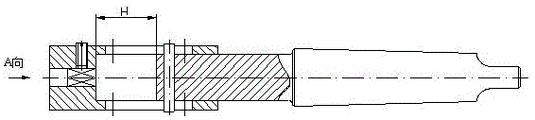
FIG. 1 is a schematic structural diagram of an internal thread following manufacturing device;
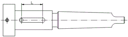
FIG. 2 is a top view of FIG. 1;
FIG. 3 is a state diagram after the internal thread is processed by a distance H;
FIG. 4 is a schematic structural view of the tap;
FIG. 5 is a schematic structural view of an external thread following manufacturing apparatus;
FIG. 6 is a top view of FIG. 5;
FIG. 7 is a view showing the external thread processed by a distance H;
fig. 8 is a schematic structural view of the die.
Wherein: 1. the screw tap comprises a screw tap body 2, a positioning screw 3, a following sleeve 4, an anti-rotation pin 5, a tail handle and a screw die 6.
Detailed Description
Example 1:
a thread following manufacturing device comprises a tail handle 5, a following sleeve 3 and a thread manufacturing part, wherein the following sleeve 3 is slidably sleeved on the tail handle 5, and the free end of the following sleeve 3 is detachably provided with the thread manufacturing part; an anti-rotation pin 4 is vertically arranged on the tail handle 5, a waist-shaped groove is correspondingly arranged on the following sleeve 3, and the anti-rotation pin 4 is connected with the waist-shaped groove in a sliding mode.
Further, the free end of the following sleeve 3 is provided with a step hole corresponding to the thread manufacturing part, a positioning screw 2 is vertically arranged on one side of the following sleeve 3, and the positioning screw 2 extends into the step hole and is fixedly abutted against one end of the thread manufacturing part. The following sleeve 3 is provided with a mounting hole corresponding to the tail handle 5, plays a role in centering when the thread is manufactured, and the following sleeve 3 moves synchronously along with the thread manufacturing part due to the positioning of the positioning screw 2 when the thread is processed.
Furthermore, the other end of the following sleeve 3 is provided with a mounting hole corresponding to the tail handle 5, and a waist-shaped groove is correspondingly arranged on the side wall of the mounting hole. The anti-rotation pin 4 can prevent the following sleeve 3 from rotating relative to the tail handle 5, and the anti-rotation pin 4 is arranged in a linear sliding mode along the length direction of the waist-shaped groove.
Further, as shown in fig. 1 and 4, and fig. 5 and 8, the thread forming portion is a tap 1 or a die 6.
The utility model discloses in the use, at first fix caudal peduncle 5 at lathe tailstock or drilling machine main shaft taper hole, fix the screw thread portion of attacking on following cover 3, when starting the main shaft rotation, it is rotatory to a direction with caudal peduncle 5, at this moment, follow cover 3 and screw thread portion of making and move forward simultaneously and carry out the screw thread preparation, process to set length after, rotatory to the opposite direction with the main shaft, at this moment, caudal peduncle 5 is rotatory to the opposite direction, follow cover 3 and screw thread portion of making and withdraw from backward simultaneously and break away from the work piece terminal surface, accomplish screw thread processing. The utility model discloses a tap 1 carries out the internal screw thread and attacks, realizes the cover system of external screw thread through die 6.
The utility model discloses a lead the lead angle guide that is had by processing screw thread itself and follow cover 3 and go ahead, eliminated because the atress when the manual tapping is uneven, the guide is inconvenient, processing is intermittent, the profile of tooth defects such as not just, make the course of working of screw thread steady, continuous, the screw thread quality can improve, simultaneously, has reduced operation intensity, has improved machining efficiency.
Example 2:
a thread following manufacturing device is shown in figures 1-4 and comprises a tail handle 5, a following sleeve 3 and a screw tap 1, wherein the following sleeve 3 is sleeved on the outer side of the tail handle 5 in a sliding mode, and the free end of the following sleeve 3 is fixed with the screw tap 1 through a positioning screw 2. An anti-rotation pin 4 is vertically arranged on the tail handle 5, a waist-shaped groove is correspondingly arranged on the following sleeve 3, and two ends of the anti-rotation pin 4 are respectively connected with the waist-shaped groove in a sliding mode. As shown in fig. 2, the maximum stroke of the thread machining is equal to the length L of the waist-shaped groove. Only a square handle is arranged at one end of the screw tap 1, and the positioning screw 2 is fixedly abutted to the square handle of the screw tap 1.
In the use process of the utility model, before machining, the tail handle 5 is pushed into a main shaft rotary hole fixed on a lathe tailstock or a drilling machine, the anti-rotation pin 4 on the tail handle 5 is arranged in a linear sliding way along the length direction of the waist-shaped groove, a part needing internal thread machining is installed and clamped, the following sleeve 3 is pulled manually to enable an orifice of the machined section end of the internal thread to be contacted with the front end of the screw tap 1, and the main shaft is started to enable a machined part to rotate to attack the internal thread; or fixing the part to be processed with external thread, manually guiding and installing the main shaft of the device to enable the front end of the die 6 to be in contact with the end part of the external thread of the workpiece to be processed, and starting the main shaft to be sheathed. As shown in fig. 3, the follower sleeve 3 is now advanced with the tap 1 during the internal thread tapping to the desired processing length H. And (3) reversing the main shaft, and moving the following sleeve 3 along with the screw tap 1 in the reverse direction until the following sleeve is separated from the end face of the processed workpiece, so that the processing of the internal thread is finished. In the process of manufacturing the internal thread, cooling liquid needs to be continuously added to the cutting part of the screw tap 1 to enable the thread to reach the due roughness.
The utility model discloses a lead the lead angle guide that is had by processing screw thread itself and follow cover 3 and go ahead, eliminated because the atress when the manual tapping is uneven, the guide is inconvenient, processing is intermittent, the profile of tooth defects such as not just, make the course of working of screw thread steady, continuous, the screw thread quality can improve, simultaneously, has reduced operation intensity, has improved machining efficiency.
Example 3:
a thread following manufacturing device is shown in figures 5-8 and comprises a tail handle 5, a following sleeve 3 and a threading die 6, wherein the following sleeve 3 is sleeved on the outer side of the tail handle 5 in a sliding mode, and the free end of the following sleeve 3 is fixed with the threading die 6 through a positioning screw 2. An anti-rotation pin 4 is vertically arranged on the tail handle 5, a waist-shaped groove is correspondingly arranged on the following sleeve 3, and two ends of the anti-rotation pin 4 are respectively connected with the waist-shaped groove in a sliding mode. As shown in fig. 6, the maximum stroke of the thread machining is equal to the length L of the kidney groove. And the threading die 6 is provided with a positioning concave hole corresponding to the positioning screw 2.
The utility model discloses in the use, to the processing of external screw thread, realize the processing of external screw thread through threading die 6, add man-hour, it is downthehole at the main shaft of lathe tailstock or drilling machine to push into tail stock 5, then, the installation clamping is good to be carried out the part of external screw thread processing, and manual drawing is followed cover 3 and is made to be contacted by external screw thread processing section terminal surface and 6 drill ways of threading die, starts the main shaft and makes the work piece rotatory. As shown in fig. 7, the follower bush 3 is moved forward while the external thread is being tightened up to the required working length H. And finally, reversing the main shaft, and moving the main shaft in the reverse direction along with the sleeve 3 until the main shaft is separated from the end face of the processed workpiece, so that the processing of the external thread is finished. The utility model can effectively keep the tooth form of the external thread and effectively ensure the coaxiality of the external thread and the required axial lead by following the coaxial cutting of the screw die 6 on the sleeve 3; the utility model discloses simple structure, the operation is convenient, but wide application in the processing manufacture process of external screw thread. In the process of sleeving the external thread, cooling liquid needs to be continuously added to the cutting part of the die 6 to ensure that the thread has proper roughness.
The utility model discloses a lead the lead angle guide that is had by processing screw thread itself and follow cover 3 and go ahead, eliminated because the atress when the manual tapping is uneven, the guide is inconvenient, processing is intermittent, the profile of tooth defects such as not just, make the course of working of screw thread steady, continuous, the screw thread quality can improve, simultaneously, has reduced operation intensity, has improved machining efficiency.
The above is only the preferred embodiment of the present invention, not to the limitation of the present invention in any form, all the technical matters of the present invention all fall into the protection scope of the present invention to any simple modification and equivalent change of the above embodiments.
Claims (6)
1. The thread following manufacturing device is characterized by comprising a tail handle (5), a following sleeve (3) and a thread tapping part, wherein the following sleeve (3) is sleeved on the tail handle (5) in a sliding manner, and the thread tapping part is detachably arranged at the free end of the following sleeve (3); the tail handle (5) is vertically provided with an anti-rotation pin (4), the following sleeve (3) is correspondingly provided with a waist-shaped groove, and the anti-rotation pin (4) is connected with the waist-shaped groove in a sliding mode.
2. A thread follow making device according to claim 1, wherein the free end of the follow sleeve (3) is provided with a stepped hole corresponding to the thread tapping part, and one side of the follow sleeve (3) is vertically provided with a positioning screw (2), and the positioning screw (2) extends into the stepped hole and is fixedly abutted against one end of the thread tapping part.
3. The thread following manufacturing device according to claim 2, wherein the other end of the following sleeve (3) is provided with a mounting hole corresponding to the tail handle (5), and a waist-shaped groove is correspondingly arranged on the side wall of the mounting hole.
4. A thread follow-up making device according to any one of claims 1-3, wherein the tapping portion is a tap (1) or a die (6).
5. A thread follow making device according to claim 1, characterized in that the free end of the tail shank (5) is provided with a taper shank or a straight shank, and is connected with the taper hole of the sleeve or the taper hole of the main shaft of the tail seat of the equipment through the taper shank or the straight shank.
6. The thread follow making device according to claim 1, wherein the length of the processed thread is equal to or less than the length of the kidney groove.
Priority Applications (1)
| Application Number | Priority Date | Filing Date | Title |
|---|---|---|---|
| CN202120824714.XU CN214721232U (en) | 2021-04-21 | 2021-04-21 | Thread following manufacturing device |
Applications Claiming Priority (1)
| Application Number | Priority Date | Filing Date | Title |
|---|---|---|---|
| CN202120824714.XU CN214721232U (en) | 2021-04-21 | 2021-04-21 | Thread following manufacturing device |
Publications (1)
| Publication Number | Publication Date |
|---|---|
| CN214721232U true CN214721232U (en) | 2021-11-16 |
Family
ID=78611816
Family Applications (1)
| Application Number | Title | Priority Date | Filing Date |
|---|---|---|---|
| CN202120824714.XU Active CN214721232U (en) | 2021-04-21 | 2021-04-21 | Thread following manufacturing device |
Country Status (1)
| Country | Link |
|---|---|
| CN (1) | CN214721232U (en) |
Cited By (1)
| Publication number | Priority date | Publication date | Assignee | Title |
|---|---|---|---|---|
| CN113118566A (en) * | 2021-04-21 | 2021-07-16 | 成都凯天电子股份有限公司 | Automatic thread machining system with dynamically adjustable machining stroke |
-
2021
- 2021-04-21 CN CN202120824714.XU patent/CN214721232U/en active Active
Cited By (1)
| Publication number | Priority date | Publication date | Assignee | Title |
|---|---|---|---|---|
| CN113118566A (en) * | 2021-04-21 | 2021-07-16 | 成都凯天电子股份有限公司 | Automatic thread machining system with dynamically adjustable machining stroke |
Similar Documents
| Publication | Publication Date | Title |
|---|---|---|
| CN205437779U (en) | Compound lathe drilling equipment of section of thick bamboo wall drilling | |
| US4141278A (en) | Polygonal turning machine | |
| CN105563123A (en) | Double-station sliding table type drilling-tapping combined machine tool | |
| CN102909420B (en) | Right-angle milling head device | |
| CN212823186U (en) | Readable automatic stroke tapping and threading device | |
| CN100574950C (en) | Method for processing thread with numerical control lathe and its thread processing tool | |
| CN101712080A (en) | Valve rod square special milling machine tool | |
| CN202963555U (en) | Drill jig of synchronizing sliding sleeve plunger chip | |
| CN202780085U (en) | Tapping clamp | |
| CN205111267U (en) | Processing equipment is appointed to automatic locking location oil of multistation | |
| CN201537754U (en) | Burr removing device for inner orifice of ferrule radial aperture | |
| CN210172979U (en) | Quick-opening and slow-opening valve core integrated special machine tool | |
| CN111906393A (en) | Readable automatic stroke tapping and threading device | |
| CN204711219U (en) | A kind of double-headstock numerically controlled lathe adjustable blade holders | |
| CN218517868U (en) | Special-shaped threaded hole machining tool | |
| CN212443604U (en) | Tapping clamp for CA6140 type common lathe | |
| CN218452604U (en) | Boring cutter machining tool | |
| CN205129476U (en) | Workpiece support device used in the spindle hole of pipe thread lathe | |
| CN201172136Y (en) | Thread processing tool for CNC lathe | |
| CN213410669U (en) | Chamfering thread milling tool | |
| CN113118566A (en) | Automatic thread machining system with dynamically adjustable machining stroke | |
| CN212239254U (en) | Automatic deep hole processing machine tool | |
| CN111496331B (en) | Machining tool and method for long-size external triangular threads | |
| CN203030946U (en) | Multifunctional tool clamp special for numerically controlled lathe | |
| CN219292774U (en) | Axial positioning tool for numerical control lathe |
Legal Events
| Date | Code | Title | Description |
|---|---|---|---|
| GR01 | Patent grant | ||
| GR01 | Patent grant |