Two-way agitating unit of salad dressing
Technical Field
The utility model relates to a salad sauce production facility technical field specifically is a two-way agitating unit of salad sauce.
Background
Salad dressing is prepared by using a large amount of eggs and oil, the most important step in the production process of salad dressing is mixing and stirring, and the taste of salad dressing is directly influenced by the effect of mixing and stirring, but the existing bidirectional stirring device for salad dressing has many problems and defects, so that the improvement of the bidirectional stirring device for salad dressing is needed.
In the process of implementing the present invention, the inventor finds that at least the following problems exist in the prior art and are not solved:
(1) the traditional bidirectional salad sauce stirring device has low mixing and stirring efficiency and poor mixing effect, and the salad sauce on the side wall in the stirring tank cannot be scraped, so that the raw material waste is easy to generate, and the use requirement cannot be met;
(2) the traditional bidirectional stirring device for the salad sauce is inconvenient to seal a feeding hole, and foreign matters easily enter the stirring tank, so that the inside of the stirring tank is polluted;
(3) the inside of the conventional bidirectional stirring device for salad dressing is very troublesome to clean and very inconvenient to use.
SUMMERY OF THE UTILITY MODEL
An object of the utility model is to provide a two-way agitating unit of salad sauce to it is lower and mix the effect relatively poor to provide the efficiency of mixing the stirring in solving above-mentioned background art, can not scrape the salad sauce on the stirring jar inner wall moreover, produces the waste of raw materials easily, can not satisfy the problem of the needs that use.
In order to achieve the above object, the utility model provides a following technical scheme: a two-way stirring device for salad sauce comprises a stirring tank and a feeding plate, wherein the feeding plate is arranged on one side of the top end of the stirring tank, the top end of the feeding plate is provided with a structure convenient to open and close, two sides of the top end inside the stirring tank are respectively provided with a mechanism convenient to clean, a feeding hole is formed inside the feeding plate, and a two-way stirring wall scraping mechanism is arranged inside the stirring tank;
wall mechanism is scraped in two-way stirring includes driving motor, driving motor fixed connection is in one side of agitator tank, driving motor's output runs through to the inside of agitator tank and the horizontal pivot of fixedly connected with through the axle sleeve, the both ends difference fixedly connected with second stirring vane of the outside both sides of horizontal pivot, the intermediate position department difference swing joint of the inside top of agitator tank and bottom has vertical pivot, the other end fixedly connected with driven gear of vertical pivot, the outside fixedly connected with driving gear of position department near the centre of horizontal pivot, the first stirring vane of fixedly connected with is distinguished to the both sides of vertical pivot, one side fixedly connected with scraper blade of first stirring vane, driven gear is provided with the box with the outside of driving gear, the box is with the inside front end fixed connection of agitator tank.
Preferably, the driven gear and the driving gear are equal in size, and the driven gear and the driving gear are in meshed connection.
Preferably, the structure of being convenient for to open and shut comprises fixed plate, handle, sealing plug, spring, first pothook and second pothook, the fixed plate sets up the top at the feed plate, the bottom fixedly connected with sealing plug of fixed plate, the top fixedly connected with handle of fixed plate, the first pothook of both sides difference fixedly connected with of fixed plate, the second pothook is the both sides on feed plate top of swing joint respectively, one side of second pothook is provided with the spring, fixed connection between spring and the feed plate.
Preferably, the outer diameter of the sealing plug is smaller than the inner diameter of the feed port, and the bottom end of the sealing plug is embedded in the feed port.
Preferably, the mechanism convenient to clean comprises a water storage tank, a water pump, a three-way pipe, a distribution cavity and a water spray nozzle, the water storage tank is fixedly connected to the middle position of the top end of the stirring tank, the water pump is fixedly connected to the front end of the water storage tank, the three-way pipe is fixedly connected to the output end of the water pump, the distribution cavity is fixedly connected to the two sides of the top end inside the stirring tank respectively, and the water spray nozzle is fixedly connected to the bottom end of the distribution cavity.
Preferably, the distribution cavity is annular, and the water spray nozzles are arranged at the bottom end of the distribution cavity at equal intervals.
Compared with the prior art, the beneficial effects of the utility model are that: the bidirectional stirring device for the salad sauce not only realizes high mixing and stirring efficiency and good mixing effect, but also can scrape the salad sauce on the inner side wall of the stirring tank, so that raw material waste is not easy to generate, the use requirement can be met, the feed inlet is convenient to seal, foreign matters are prevented from entering the stirring tank to prevent the inside of the stirring tank from being polluted, the inside is very simple to clean, and the use is very convenient;
(1) by arranging the bidirectional stirring wall scraping mechanism, the bidirectional stirring wall scraping mechanism comprises a driving motor, the driving motor is fixedly connected with one side of the stirring tank, the output end of the driving motor penetrates into the stirring tank through a shaft sleeve and is fixedly connected with a transverse rotating shaft, two ends of two sides outside the transverse rotating shaft are respectively and fixedly connected with a second stirring blade, a vertical rotating shaft is respectively and movably connected with the middle positions of the top end and the bottom end inside the stirring tank, the other end of the vertical rotating shaft is fixedly connected with a driven gear, a driving gear is fixedly connected with the position close to the middle outside the transverse rotating shaft, two sides of the vertical rotating shaft are respectively and fixedly connected with a first stirring blade, one side of the first stirring blade is fixedly connected with a scraper blade, the driven gear and the outside of the driving gear are provided with a box body, the box body is fixedly connected with the front end inside the stirring tank, when in use, the driving motor is started, the driving motor drives the transverse rotating shaft to rotate, the second stirring blades on two sides of the outer portion of the transverse rotating shaft can longitudinally stir and mix salad sauce, the driving gear on the outer portion of the transverse rotating shaft can drive the driven gear to rotate, the driven gear drives the vertical rotating shaft to rotate, and the first stirring blades on two sides of the outer portion of the vertical rotating shaft can transversely stir and mix the salad sauce, so that the salad sauce can be stirred and mixed bidirectionally;
(2) by arranging the fixing plate, the handle, the sealing plug, the spring, the first clamping hook and the second clamping hook, when the stirring tank is used, the sealing plug at the bottom of the fixing plate is inserted into the feeding hole, then the fixing plate is pressed downwards to enable the spring to contract, at the moment, the second clamping hook is buckled on the first clamping hook, then the fixing plate is loosened, so that under the action of the reset elastic force of the spring, the first clamping hook and the second clamping hook are clamped and locked with each other, the inner part of the stirring tank can be sealed, foreign matters are prevented from entering the inner part of the stirring tank, when the fixing plate needs to be disassembled, only the fixing plate needs to be pressed to enable the first clamping hook to be pressed downwards, at the moment, the second clamping hook is turned to one side, then the handle is pulled, the sealing plug is pulled out of the inner part of the feeding hole, the opening and closing of the feeding hole can be conveniently controlled, and the inner part of the stirring tank is prevented from being polluted;
(3) through being provided with storage water tank, water pump, three-way pipe, distribution chamber and water sprayhead, after using, start the water pump, the water pump can take the inside clear water of storage water tank out to pour into the inside in distribution chamber into through the three-way pipe, evenly spray the inside at the agitator tank through water sprayhead at last, just so can wash the inside of agitator tank, easy operation, it is very convenient to use.
Drawings
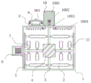
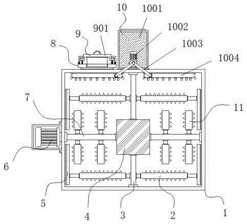
Fig. 1 is a schematic front view of a cross-sectional structure of the present invention;
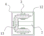
FIG. 2 is a schematic view of the enlarged structure of the front section of the case body of the present invention;
FIG. 3 is a schematic view of the front view partial section enlarged structure of the structure convenient for opening and closing of the present invention;
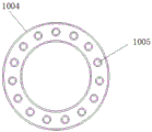
fig. 4 is a schematic view of the bottom structure of the distribution chamber of the present invention.
In the figure: 1. a stirring tank; 2. a first stirring blade; 3. a vertical rotating shaft; 4. a box body; 5. a squeegee; 6. a drive motor; 7. a transverse rotating shaft; 8. a feeding plate; 9. the structure is convenient to open and close; 901. a fixing plate; 902. a handle; 903. a sealing plug; 904. a spring; 905. a first hook; 906. a second hook; 10. the mechanism is convenient to clean; 1001. a water storage tank; 1002. a water pump; 1003. a three-way pipe; 1004. a distribution chamber; 1005. a water spray nozzle; 11. a second stirring blade; 12. a driven gear; 13. a driving gear; 14. and (4) feeding a material inlet.
Detailed Description
The technical solutions in the embodiments of the present invention will be described clearly and completely with reference to the accompanying drawings in the embodiments of the present invention, and it is obvious that the described embodiments are only some embodiments of the present invention, not all embodiments. Based on the embodiments in the present invention, all other embodiments obtained by a person skilled in the art without creative work belong to the protection scope of the present invention.
Example 1: referring to fig. 1-4, a bidirectional stirring device for salad sauce comprises a stirring tank 1 and a feeding plate 8, wherein the feeding plate 8 is arranged on one side of the top end of the stirring tank 1, the top end of the feeding plate 8 is provided with a structure 9 convenient to open and close, two sides of the top end inside the stirring tank 1 are respectively provided with a mechanism 10 convenient to clean, a feeding hole 14 is arranged inside the feeding plate 8, and a bidirectional stirring wall scraping mechanism is arranged inside the stirring tank 1;
referring to fig. 1-4, a bidirectional stirring device for salad sauce further comprises a bidirectional stirring wall-scraping mechanism, the bidirectional stirring wall-scraping mechanism comprises a driving motor 6, the driving motor 6 is fixedly connected to one side of the stirring tank 1, the model of the driving motor 6 can be Y90S-2, the output end of the driving motor 6 penetrates through the stirring tank 1 through a shaft sleeve and is fixedly connected with a transverse rotating shaft 7, two ends of two sides of the outside of the transverse rotating shaft 7 are respectively and fixedly connected with a second stirring blade 11, the middle positions of the top end and the bottom end of the inside of the stirring tank 1 are respectively and movably connected with a vertical rotating shaft 3, the other end of the vertical rotating shaft 3 is fixedly connected with a driven gear 12, the position of the outside of the transverse rotating shaft 7 close to the middle is fixedly connected with a driving gear 13, two sides of the vertical rotating shaft 3 are respectively and fixedly connected with a first stirring blade 2, one side of the first stirring blade 2 is fixedly connected with a scraping plate 5, a box body 4 is arranged outside the driven gear 12 and the driving gear 13, and the box body 4 is fixedly connected with the front end inside the stirring tank 1;
the driven gear 12 and the driving gear 13 are equal in size, and the driven gear 12 and the driving gear 13 are in meshed connection;
specifically, as shown in fig. 1 and 2, when using, start driving motor 6, driving motor 6 drives transverse rotating shaft 7 and rotates, second stirring vane 11 of the outside both sides of transverse rotating shaft 7 can carry out fore-and-aft stirring and mix to salad dressing, driving gear 13 of the outside of transverse rotating shaft 7 can drive driven gear 12 and rotate simultaneously, driven gear 12 drives vertical rotating shaft 3 and rotates, first stirring vane 2 of the outside both sides of vertical rotating shaft 3 can carry out horizontal stirring and mix to salad dressing, can carry out two-way stirring and mix to salad dressing like this, and simple structure, save economic cost, and when taking out salad dressing out, scraper blade 5 can also scrape adnexed salad dressing down on agitator tank 1 inside wall, do not need manual operation, raw materials and cost of labor have been practiced thrift greatly, can satisfy the needs of using.
Example 2: the structure 9 convenient to open and close is composed of a fixing plate 901, a handle 902, a sealing plug 903, a spring 904, a first clamping hook 905 and a second clamping hook 906, wherein the fixing plate 901 is arranged at the top end of the feeding plate 8, the bottom end of the fixing plate 901 is fixedly connected with the sealing plug 903, the top end of the fixing plate 901 is fixedly connected with the handle 902, the two sides of the fixing plate 901 are respectively and fixedly connected with the first clamping hook 905, the second clamping hook 906 is respectively and movably hinged at the two sides of the top end of the feeding plate 8, one side of the second clamping hook 906 is provided with the spring 904, and the spring 904 is fixedly connected with the feeding plate 8;
the outer diameter of the sealing plug 903 is smaller than the inner diameter of the feed port 14, and the bottom end of the sealing plug 903 is embedded in the feed port 14;
specifically, as shown in fig. 1 and fig. 3, when in use, the sealing plug 903 at the bottom of the fixing plate 901 is inserted into the interior of the feed port 14, and then the fixing plate 901 is pressed downward to contract the spring 904, at this time, the second hook 906 is buckled on the first hook 905, and then the fixing plate 901 is released, so that under the action of the restoring elastic force of the spring 904, the first hook 905 and the second hook 906 are mutually locked, so that the interior of the stirring tank 1 can be sealed, and foreign matters are prevented from entering the interior of the stirring tank 1, when the fixing plate 901 needs to be detached, only the fixing plate 901 needs to be pressed to press the first hook 905 downward, at this time, the second hook 906 is turned over to one side, and then the handle 902 is pulled to pull out the sealing plug 903 from the interior of the feed port 14, so that the opening and closing of the feed port 14 can be conveniently controlled, and the interior of the stirring tank 1 is prevented from being polluted.
Example 3: the cleaning mechanism 10 consists of a water storage tank 1001, a water pump 1002, a three-way pipe 1003, a distribution cavity 1004 and a water spray nozzle 1005, wherein the water storage tank 1001 is fixedly connected to the middle position of the top end of the stirring tank 1, the water pump 1002 is fixedly connected to the front end of the water storage tank 1001, the water pump 1002 can be QBK-25 in type, the three-way pipe 1003 is fixedly connected to the output end of the water pump 1002, the distribution cavities 1004 are respectively and fixedly connected to two sides of the top end inside the stirring tank 1, and the water spray nozzle 1005 is fixedly connected to the bottom end of the distribution cavity 1004;
the distribution cavity 1004 is annular, and the water spray nozzles 1005 are arranged at the bottom end of the distribution cavity 1004 at equal intervals;
specifically, as shown in fig. 1 and 4, after use, the water pump 1002 is started, the water pump 1002 pumps clean water out of the water storage tank 1001, the clean water is injected into the distribution chamber 1004 through the three-way pipe 1003, and the clean water is finally uniformly sprayed into the stirring tank 1 through the water spray nozzle 1005, so that the interior of the stirring tank 1 can be cleaned, the operation is simple, and the use is very convenient.
The working principle is as follows: the utility model discloses when using, at first, when using, start driving motor 6, driving motor 6 drives transverse shaft 7 and rotates, the second stirring vane 11 of 7 outside both sides of transverse shaft can carry out fore-and-aft stirring to salad dressing and mix, 7 outside driving gear 13 of transverse shaft can drive driven gear 12 and rotate simultaneously, driven gear 12 drives vertical pivot 3 and rotates, the first stirring vane 2 of 3 outside both sides of vertical pivot can carry out horizontal stirring to salad dressing and mix, can carry out two-way stirring to salad dressing and mix like this, and simple structure, and economic cost is saved, and when taking out salad dressing, scraper blade 5 can also scrape adnexed salad dressing on agitator tank 1 inside wall, do not need manual operation, raw materials and cost of labor have been practiced thrift greatly, can satisfy the needs that use.
Later, when using, the sealing plug 903 at the bottom of the fixing plate 901 is inserted into the interior of the feed inlet 14, then the fixing plate 901 is pressed downwards, the spring 904 is contracted, at the moment, the second hook 906 is buckled on the first hook 905, then the fixing plate 901 is loosened, so that under the action of the reset elastic force of the spring 904, the first hook 905 and the second hook 906 are mutually clamped and locked, the interior of the stirring tank 1 can be sealed, foreign matters are prevented from entering the interior of the stirring tank 1, when the fixing plate 901 needs to be detached, only the fixing plate 901 is pressed, the sealing plug 905 is pressed downwards, at the moment, the second hook 906 is turned towards one side, then the handle 902 is pulled, the 903 is pulled out from the interior of the feed inlet 14, and therefore, the opening and closing of the feed inlet 14 can be conveniently controlled, and the interior of the stirring tank 1 is prevented from being polluted.
Finally, after the mixer is used, the water pump 1002 is started, the water pump 1002 pumps out clean water in the water storage tank 1001, the clean water is injected into the distribution cavity 1004 through the three-way pipe 1003, and the clean water is uniformly sprayed into the mixer 1 through the water spray nozzles 1005, so that the interior of the mixer 1 can be cleaned, the operation is simple, and the use is very convenient.
It is obvious to a person skilled in the art that the invention is not restricted to details of the above-described exemplary embodiments, but that it can be implemented in other specific forms without departing from the spirit or essential characteristics of the invention. The present embodiments are therefore to be considered in all respects as illustrative and not restrictive, the scope of the invention being indicated by the appended claims rather than by the foregoing description, and all changes which come within the meaning and range of equivalency of the claims are therefore intended to be embraced therein. Any reference sign in a claim should not be construed as limiting the claim concerned.