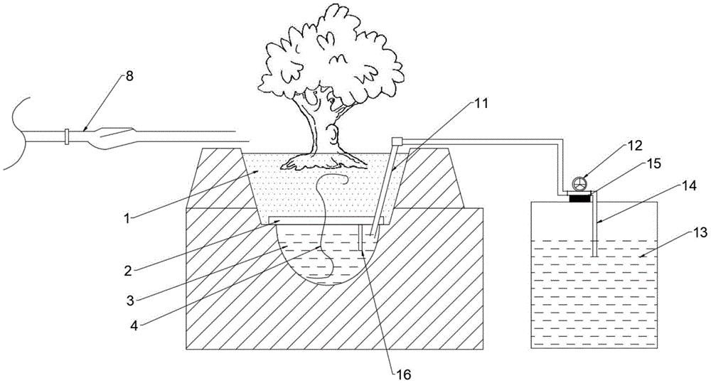
Planting hole with stable water supply structure
Technical Field
The utility model relates to an agricultural planting technical field, in particular to planting hole cave with stabilize water supply structure.
Background
Irrigation, namely irrigate the ground with water, the irrigation principle is that irrigation volume, irrigation frequency and time need be according to medicinal plant water demand characteristic, growing stage, weather, soil condition and decide, in good time, a proper amount, reasonable irrigation, for the technological measure of ground supply crop required moisture, in order to guarantee crop normal growth, obtain high and stable yield, must supply the crop with sufficient moisture, under natural condition, often because of precipitation is not enough or the inhomogeneous that distributes, can not satisfy the crop to the moisture requirement, consequently, must artificially irrigate, in order to compensate natural rainfall not enough, but artificial irrigation receives factors such as water pressure, rivers to influence, also lead to rivers inhomogeneous easily, cause the impact to plant or soil, consequently, the utility model provides a plant pit cave with stable water supply structure.
SUMMERY OF THE UTILITY MODEL
To the above-mentioned not enough among the prior art, the utility model provides a plant hole cave with stabilize water supply structure, its simple structure is reasonable, the convenient popularization.
A planting pit hole with a stable water supply structure comprises a planting pit hole, an external water inlet device and an internal water inlet device, wherein a baffle is arranged at the bottom of the planting pit hole, a reservoir is arranged at the bottom of the baffle, a water absorption cotton thread is arranged in the reservoir, and the other end of the water absorption cotton thread extends into the planting pit hole through the baffle;
the external water inlet device comprises a water main, a water distribution pipe communicated with the water main and a branch water pipe communicated with the water distribution pipe, wherein the tail end of the branch water pipe is provided with a flow controller, and the flow controller comprises an outer shell and an elastic baffle plate arranged inside the outer shell;
inside water installations includes inlet tube, water pump and water supply tank, the inlet tube passes through the baffle is located in the cistern, the delivery port of water pump with advance water piping connection, the water inlet of water pump pass through the drinking-water pipe connect in the water supply tank, the bottom of water pump is equipped with the controller, still install level sensor in the cistern, the water pump with level sensor all with the controller is connected.
Preferably, one end of the elastic baffle is fixed inside the outer shell, and the other end of the elastic baffle is opposite to the direction of water flow.
Preferably, the elastic baffle is made of an elastic material, and the inner diameter of the outer shell is larger than that of the branch water pipe.
Preferably, the inner walls of the planting pit holes and the inner wall of the reservoir are provided with waterproof isolation layers, planting matrixes are arranged in the planting pit holes, and plants are planted on the planting matrixes.
Preferably, a filter mesh is arranged between the water main and the water distribution pipe, and a switch is arranged on the water distribution pipe.
Preferably, when the liquid level sensor detects that the water level in the water storage tank is lower than a threshold value, the controller controls the water pump to start; and when the liquid level sensor detects that the water level in the water storage tank is not lower than a threshold value, the water pump stops working.
The utility model has the advantages that:
the utility model discloses a mode that inside and outside combine supplies water to the plant, and outside water installations can realize that discharge is stable, inside water installations detectable liquid level to automatic retaining, easy operation supplies water stably, guarantees the plant normal growth. The utility model is suitable for a fresh water volume scarce area plants the hole and can become the scale building, has the significance to the planting and the afforestation of crops.
Drawings
In order to more clearly illustrate the technical solutions of the embodiments of the present invention, the drawings that are required to be used in the embodiments will be briefly described below, it should be understood that the following drawings only illustrate some embodiments of the present invention, and therefore should not be considered as limiting the scope, and for those skilled in the art, other related drawings can be obtained according to the drawings without inventive efforts.
Fig. 1 is a schematic structural view of the present invention;
FIG. 2 is a schematic view of an external water intake device;
FIG. 3 is a schematic view of the elastic baffle;
1-planting pit holes, 2-baffles, 3-water storage tank, 4-absorbent cotton thread, 5-water main, 6-water diversion pipe, 7-branch water pipe, 8-flow controller, 9-outer shell, 10-elastic baffle, 11-water inlet pipe, 12-water pump, 13-water supply tank, 14-water pumping pipe, 15-controller, 16-liquid level sensor, 17-filter screen and 18-switch.
Detailed Description
In order to make the objects, technical solutions and advantages of the present invention easier to be clearly understood, the technical solutions in the embodiments of the present invention will be clearly and completely described below with reference to the accompanying drawings in the embodiments of the present invention, and it is obvious that the described embodiments are some, but not all embodiments of the present invention. The components of embodiments of the present invention, as generally described and illustrated in the figures herein, may be arranged and designed in a wide variety of different configurations.
In the description of the present invention, it should be noted that the terms "center", "upper", "lower", "left", "right", "vertical", "horizontal", "inner", "outer", and the like indicate orientations or positional relationships based on the orientations or positional relationships shown in the drawings, and are only used for convenience of description and simplification of description, but do not indicate or imply that the device or element referred to must have a specific orientation, be constructed in a specific orientation, and be operated, and thus, should not be construed as limiting the present invention.
As shown in the attached drawings, the planting pit hole with the stable water supply structure comprises a planting pit hole 1, an external water inlet device and an internal water inlet device, wherein a baffle 2 is arranged at the bottom of the planting pit hole 1, a reservoir 3 is arranged at the bottom of the baffle 2, a water absorption cotton thread 4 is arranged in the reservoir 3, and the other end of the water absorption cotton thread 4 extends into the planting pit hole 1 through the baffle 2;
the external water inlet device comprises a water main pipe 5, a water distribution pipe 6 communicated with the water main pipe 5 and a water branch pipe 7 communicated with the water distribution pipe 6, wherein the tail end of the water branch pipe 7 is provided with a flow controller 8, and the flow controller 8 comprises an outer shell 9 and an elastic baffle 10 arranged inside the outer shell 9;
inside water installations includes inlet tube 11, water pump 12 and water supply tank 13, and inlet tube 11 passes through baffle 2 and locates in cistern 3, and the delivery port and the inlet tube 11 of water pump 12 are connected, and the water inlet of water pump 12 passes through drinking-water pipe 14 to be connected in water supply tank 13, and the bottom of water pump 12 is equipped with controller 15, still installs level sensor 16 in the cistern 3, and water pump 12 and level sensor 16 all are connected with controller 15.
In this embodiment, one end of the elastic baffle 10 is fixed inside the outer shell 9, and the other end is opposite to the direction of water flow; the elastic baffle piece 10 is made of elastic material, and the inner diameter of the outer shell 9 is larger than that of the branch water pipe 7.
The inner wall of the planting pit 1 and the inner wall of the reservoir 3 are provided with waterproof isolation layers, planting substrates are arranged in the planting pit 1, and plants are planted on the planting substrates.
A filter screen 17 is arranged between the water main 5 and the water distribution pipe 6, and a switch 18 is arranged on the water distribution pipe 6.
When in use, the water inlet device can be used in a mode of combining external water inlet with internal water inlet, or can be used independently. When the water flow in the water diversion pipe 6 is too large, the elastic blocking piece 10 is impacted, the elastic blocking piece 10 deforms, the space in the flow controller 8 is occupied, the water flow channel is reduced, and the water flow is reduced; when the water flow in the distributive pipe 6 is too small, the elastic baffle piece 10 is not deformed, the water flow channel is enlarged, and the water flow is increased, so that the water yield of the flow controller 8 is still stable when the water flow of the distributive pipe 6 is unstable, and the influence of the water flow of the distributive pipe 6 on watering is reduced.
The internal water inlet device is provided with a liquid level sensor 16, and when the liquid level sensor 16 detects that the water level in the reservoir 3 is lower than a threshold value, the controller 15 controls the water pump 12 to start; when the level sensor 16 detects that the water level in the reservoir 3 is not below the threshold value, the water pump 12 stops operating.
The utility model discloses a mode that inside and outside combine supplies water to the plant, and outside water installations can realize that discharge is stable, inside water installations detectable liquid level to automatic retaining, easy operation supplies water stably, guarantees the plant normal growth. The utility model is suitable for a fresh water volume scarce area plants the hole and can become the scale building, has the significance to the planting and the afforestation of crops.
The above description is only for the purpose of illustrating the preferred embodiments of the present invention and is not intended to limit the present invention, and all modifications, equivalents, improvements and the like that are made within the spirit and principles of the present invention are intended to be included within the scope of the present invention.