Double-rake lifting type potato combine harvester
Technical Field
The utility model relates to the technical field of agricultural machinery, concretely relates to two disks lift formula potato combine.
Background
The potato planting area occupies a large proportion in China all the time, and compared with the mechanization degree of grain crops such as wheat, rice, corn and the like, the mechanization technology and machines in all links of potato production are slow to develop, and great difficulty is faced. In areas where large implements can be used, potato combines have achieved some success. However, in the area where small and medium-sized machines operate, the current mechanized harvesting mode mainly adopts a mode of combining machine excavation and manual picking, the link of manual picking enables the potato harvesting cost to be always high, the single body has high labor intensity, low efficiency and high cost, and the requirement of full-range mechanization of potato seed harvesting cannot be met. The potato picking machine suitable for small plot areas and good in operation performance is urgently needed by operation main bodies such as potato planting households and cooperative society, and the working reliability and the working efficiency are improved.
SUMMERY OF THE UTILITY MODEL
The utility model aims to solve the technical problem that not enough of machines are picked up to current potato and provide a two raking tray lift transport formula potato combine of collecting the potato to excavate, pick up, vanning, uninstallation in an organic whole, saved the results cost of potato greatly, improved production efficiency.
For solving the technical problem of the utility model, adopt the following technical scheme:
the utility model provides a two dishes lift formula potato combine of hugging, includes frame, draw gear, hugs a set assembly, power take off, one-level conveyor, second grade conveyor, buffer, the frame front end sets up draw gear, the mid-mounting power take off of frame, frame middle part below both sides installation land wheel, the draw gear front below sets up and hugs a set assembly, hug the rack slope installation one-level conveyor at set assembly rear, set up second grade conveyor in the frame at one-level conveyor rear, second grade conveyor's rear below installation carriage, the rear upper portion in the frame is installed in the carriage, power take off connects the drive and hugs a set assembly, one-level conveyor and second grade conveyor.
And the carriage is provided with a buffer device which has a buffer effect on potatoes falling from the rear end of the secondary conveying device.
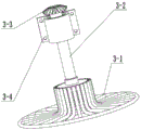
Hug a set assembly and include that two revolve to inside and opposite careless cap-shaped hugs the dish, careless cap-shaped hugs a set top and sets up and hug a set axle, hug a set axle movable mounting in the frame, hug a set axle and be driven by power take off.
The primary conveying device comprises a driven roller and a driving roller, a vibrating screen is sleeved between the driven roller and the driving roller, and the driving roller is connected with a power output device.
Buffer includes buffer footing, second grade buffering mount, one-level buffering mount, the buffer footing is installed on the carriage, second grade buffering mount and one-level buffering mount are installed respectively on the buffer footing of carriage both sides, both sides between the second grade buffering mount and both sides set up buffering cloth curtain between the one-level buffering mount, buffering cloth curtain between the one-level buffering mount is located second grade conveyor rear end below.
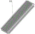
The secondary conveying device comprises a secondary conveying device frame, a conveying belt driven shaft and a conveying belt driving shaft are arranged at the upper end and the lower end of the secondary conveying device frame, a plurality of conveying belt carrier rollers are arranged on the secondary conveying device frame between the conveying belt driven shaft and the conveying belt driving shaft, and a conveying belt provided with a scraper is sleeved between the conveying belt driven shaft and the conveying belt driving shaft.
Set up the conveyer belt regulating plate in the second grade conveyor frame, the elasticity degree of conveyer belt is adjusted through the position control conveyer belt of adjusting the conveyer belt driven shaft to the conveyer belt regulating plate.
The conveying belt side plates are arranged on two sides of the conveying belt and are nested in a belt groove of a driven shaft of the conveying belt.
And a hydraulic oil cylinder is arranged between the carriage and the frame, the hydraulic oil cylinder realizes the overturning of the carriage, and the hydraulic oil cylinder is connected with a hydraulic system of a tractor for towing machines and tools.
The driving roller is toothed, and the driving roller is matched with the vibrating screen to realize vibration.
The utility model provides a potato combine harvester which integrates potato digging, automatic picking, boxing and unloading. The potato planter has the advantages that the whole machine is compact in structure and reasonable in space distribution, the potato tuber digging and gathering are carried out by the aid of the raking plate assembly, the raking plates with different gaps and changeable sizes can be picked up according to needs, applicability of the machine is enhanced, and digging requirements of potato tubers with different planting line distances can be met. The potato blocks on the seed row are excavated and raked by the raking plate assembly and are conveyed to the conveying device for lifting and boxing, the impurity rate of the potato blocks is reduced by the vibration effect of the first-stage conveying device, the large-angle lifting of the potatoes is guaranteed by the vertical scraper plate arranged on the second-stage conveying belt, meanwhile, the tightness of the conveying belt can be adjusted by the conveying device, the adaptability of machines and tools is enhanced, and the two-stage buffer device is designed at the rear end of the second-stage conveying belt to reduce the skin breaking rate and the potato injury rate of the machines and tools; the automatic unloading is carried out by using a hydraulic system carried by the tractor, so that the labor intensity is reduced.
Drawings
Fig. 1 is a schematic isometric structural view of the whole machine of the present invention;
FIG. 2 is a schematic view of the frame structure of the present invention;
fig. 3 is a schematic view of the suspension structure of the present invention;
FIG. 4 is a schematic view of the structure of the rack of the present invention;
FIG. 5 is a schematic structural view of components of the primary conveying device of the present invention;
FIG. 6 is a schematic view of a part of the components of the primary conveying device of the present invention;
FIG. 7 is a schematic view of the vibrating screen of the present invention;
FIG. 8 is a schematic view of the land wheel structure of the present invention;
FIG. 9 is a schematic structural view of a carriage assembly of the present invention;
fig. 10 is a schematic structural view of the carriage hydraulic part assembly of the present invention;
fig. 11 is a schematic structural view of the buffering device of the present invention;
FIG. 12 is a schematic view of a part of the components of the second stage conveying device according to the present invention;
fig. 13 is a schematic structural view of the secondary conveyer belt of the present invention;
fig. 14 is a schematic view of the assembly structure of another part of the secondary conveying device of the present invention;
fig. 15 is a schematic structural view of a protective cover of the conveying chain of the present invention;
fig. 16 is a schematic structural view of the power output apparatus of the present invention;
fig. 17 is a schematic structural view of a part of components of the power output apparatus of the present invention.
Detailed Description
The invention will be described in detail below, in whole or in part, with reference to the accompanying drawings:
as shown in fig. 1, 2, 3 and 4, the double-holding-disc lifting type potato combine harvester comprises a frame 1, a traction device 2, a holding disc assembly 3, a power output device 9, a primary conveying device 4, a secondary conveying device 8, a buffer device 7, a carriage 6 and ground wheels 5, wherein the traction device 2 is installed at the front end of the frame 1, the power output device 9 is installed in the middle of the frame 1, the ground wheels 5 are installed on two sides of the middle lower portion of the frame 2, the holding disc assembly 3 is arranged below the traction device 2, the primary conveying device 4 is installed on the frame 1 behind the holding disc assembly 3 in a tilting mode, the secondary conveying device 8 is arranged on the frame 1 behind the primary conveying device 4, and the carriage 6 is installed on the frame 1 below the rear end of the secondary conveying device 8. The whole traction device 2 is connected with the machine frame 1 through the traction longitudinal beam 2-6, and the whole machine is adjusted left and right through the pin shaft 2-4 after being articulated, so that the whole machine can be well adapted to the ridge distance to smoothly complete excavation and picking tasks. A holding plate assembly 3 is arranged at the rear lower part of the traction device 2, the holding plate assembly 3 is divided into a left group and a right group, each group consists of a straw cap-shaped holding plate 3-1, a holding plate shaft 3-2, a driven bevel gear 3-3 and a holding plate bearing seat 3-4, the holding plate assembly 3 holds the potatoes which are excavated and collected into strips to a first-stage conveying device 4 to complete the picking task, the rotating directions of the left and right strawhat-shaped holding discs 3-1 are opposite, the strawhat-shaped holding discs 3-1 are designed according to the shapes of potato blocks, which is beneficial to holding potatoes, the holding disc assembly 3 drives the driven bevel gear 3-3 to rotate by the power of the power output device 9, the driven bevel gear 3-3 and the holding disc shaft 3-2 are made into a whole, the potato raking machine is welded with the raking disc 3-1 and then penetrates through the raking disc bearing seat 3-4 to perform rotary potato raking operation, and the raking disc assembly 3 is fixed on the rack 1 through the raking disc bearing seat 3-4 by bolts.
As shown in fig. 5, 6 and 7, a primary conveying device 4 is arranged behind a rake assembly 3, the primary conveying device 4 is driven by a power output device 9 through a chain wheel, the primary conveying device 4 comprises a driven roller 4-1, a vibrating screen side plate 4-2, a driving chain wheel 4-3, a vibrating screen 4-4, a driving roller 4-5 and a vibrating screen guard plate 4-6, the driving chain wheel 4-3 is driven by power output by the power output device 9, the driving roller 4-5 is connected with the driving chain wheel 4-3, the driving chain wheel 4-3 drives the driving roller 4-5 to rotate to drive the vibrating screen 4-4 to rotate, the vibrating screen 4-4 conveys potato blocks to a secondary conveying device 8 for boxing, and the driving roller 4-5 is in a tooth shape and is matched with the vibrating screen 4-4 to realize vibration, sundries such as soil blocks can be leaked out from gaps of the vibration sieve 4-4 through vibration crushing to complete impurity removal operation, the vibration sieve side plate 4-2 is used for mounting a driving chain wheel 4-3, a driven roller 4-1 and the like, a vibration sieve protection plate 4-6 plays a role in protecting the holding tray assembly 3 on one hand, and the holding tray assembly 3 is matched with the holding tray assembly 3 to convey the held potato blocks in a centralized mode on the other hand.
As shown in fig. 8, 9, 10 and 11, land wheels 5 are arranged on two sides of the primary conveying device 4, each land wheel 5 comprises a wheel upright 5-1, a hub shaft 5-2, a hub 5-3, a wheel 5-4 and the like, the wheel upright 5-1 is used for fixing the land wheel 5, two ball bearings are arranged in the hub 5-3 and are connected with the wheel 5-4 through bolts, and then all parts cooperate with each other to enable the land wheel 5 to rotate. A carriage 6 is arranged above the land wheels 5, the carriage 6 comprises a front wall plate 6-1, a side wall plate 6-2, a rear wall plate 6-3, a carriage hook 6-4, a carriage pull rod 6-5, a hydraulic oil cylinder 6-6, a hydraulic oil pipe 6-7, an oil pipe joint 6-8 and the like, the front wall plate 6-1 and the side wall plate 6-2 are welded into a whole, the upper part of the rear wall plate 6-3 is hinged to the two side wall plates 6-2, the lower part of the rear wall plate is adjusted and fixed by the carriage hook 6-4, the carriage pull rod 6-5 and the like, the hydraulic oil cylinder 6-6 is communicated with liquid and extends after the carriage 6 is filled with potato blocks, the carriage hook 6-4 and the carriage pull rod 6-5 are opened, potatoes in the carriage 6 are unloaded, and the circular work is carried out. The hydraulic oil cylinder 6-6 is connected with a hydraulic system of the tractor through an inlet hydraulic oil pipe 6-7, an outlet hydraulic oil pipe 6-7 and an oil pipe joint 6-8, and the potato blocks in the carriage 6 are unloaded by the aid of the hydraulic system of the tractor, so that labor is saved. The carriage 6 is provided with the buffer device 7, the buffer device 7 performs buffering in two steps, the buffer device comprises buffer frame feet 7-1, a second-level buffer fixing frame 7-2 and a first-level buffer fixing frame 7-3, the buffer frame feet 7-1 are in pin joint with the carriage 6 to play a fixing role, the second-level buffer fixing frame 7-2 and the first-level buffer fixing frame 7-3 are respectively controlled to be in a group, the potatoes are connected through a buffer curtain, after falling off from the second-level conveying device 8, are buffered through the curtain on the first-level buffer fixing frame 7-3 and then buffered through the curtain on the second-level buffer fixing frame 7-2, and finally fall into the carriage 6, the buffer device 7 can effectively reduce the potato injury rate and the potato breakage rate, and is favorable for storing potatoes.
As shown in the figures 12, 13, 14 and 15, the front end of a buffer device 7 is provided with a secondary conveying device 8, the secondary conveying device 8 comprises a conveying belt adjusting plate 8-1, a conveying belt side plate 8-2, a conveying belt driving chain wheel 8-3, a conveying belt top cover 8-4, a conveying belt 8-5, a conveying belt driven shaft 8-6, a conveying belt roller 8-7, a secondary conveying device side beam 8-8, a conveying belt driving shaft 8-9, a conveying chain protective cover 8-10 and the like, the conveying belt adjusting plate 8-1 is used for adjusting the tightness of the conveying belt 8-5 to ensure the smooth lifting and conveying of potato chips, the conveying belt side plates 8-2 are arranged on two sides of the conveying belt 8-5 and are arranged in a belt groove of the conveying belt driven shaft 8-6, a certain gap is formed between the two belts, and when the conveying belt driving shaft 8-9 rotates, a reinforcing steel bar rib in the center of the two belts is just clamped on the conveying belt driving shaft 8-9 In the tooth grooves of the two chain wheels, the conveying belts 8-5 are guaranteed to rotate continuously, meanwhile, the conveying belts 8-5 are further provided with scraping plates, potato block lifting is facilitated, potato blocks are guaranteed to be conveyed into the carriage 6 smoothly after falling from the first-stage conveying device 4, meanwhile, the conveying belts 8-5 are guaranteed to be located at the best working position constantly by the aid of the two groups of conveying belt carrier rollers 8-7 which are arranged at equal intervals, bearings are arranged on the two sides of each conveying belt carrier roller 8-7 and installed on the side beams 8-8 of the second-stage conveying device, and the conveying chain shields 8-10 are arranged to prevent the chains from falling off and further influence secondary lifting of the potato blocks.
As shown in fig. 16 and 17, the power output device 9 is arranged at the upper end of the holding tray assembly 3, the power output device 9 comprises a transmission 9-1, a holding tray driving chain 9-2, a conveying device driving chain 9-3, a primary conveying device driving chain 9-4, a secondary conveying device driving chain 9-5 and a holding tray input shaft 9-6, and all parts in the power output device 9 are matched with each other to complete power output and transmission of the whole machine.