Device for stripping communication optical cable
Technical Field
The utility model relates to an optical cable equipment technical field especially relates to a device of stripping communication optical cable.
Background
When the optical cable enters the optical distribution equipment, the sheath outside the optical cable must be peeled off to expose the optical fiber and protected by a flexible sleeve.
The structure of the conventional stripping tool for communication optical cables, such as the structure disclosed in application number 201721472594.1, the utility model is a multifunctional rubber-insulated-wire cable stripping pliers, which needs to be twisted back and forth on the surface of the optical cable during use to facilitate the clamping and stripping of the outer jacket of the optical cable, and in the process, the clamping part of the tool can cause irreversible damage to the optical fiber.
SUMMERY OF THE UTILITY MODEL
An object of the utility model is to provide a device of stripping communication optical cable to damage the technical problem of optic fibre easily when stripping the fiber surface overcoat in overcoming prior art.
In order to achieve the technical purpose, the utility model provides a following technical scheme:
a device for stripping a communication optical cable comprises a cover body, wherein a transverse cutting assembly is mounted on the front end face of the cover body, a plurality of positioning holes are formed in the front end face of the transverse cutting assembly, the centers of the plurality of positioning holes are located on the same horizontal line, and the plurality of positioning holes are arranged at intervals and are arranged along the length direction of the transverse cutting assembly; the top end and the bottom end of the transverse cutting assembly are both connected with transverse cutters, and the transverse cutters positioned at the top end and the bottom end are provided with arc openings corresponding to the positioning holes;
the rear end surface of the cover body is fixedly connected with a side supporting seat, a plurality of observation holes are arranged on the side supporting seat at intervals, the observation holes are arranged corresponding to the positioning holes, and each positioning hole corresponds to one observation hole;
a rotating assembly is arranged in the cover body close to the bottom, two ends of the rotating assembly are rotatably connected in the cover body, a plurality of cable grooves are uniformly formed in the outer surface of the rotating assembly, each cable groove corresponds to one positioning hole and one observation hole, and an optical cable to be peeled extends into the cable groove through the positioning hole and extends out of the device through the observation hole;
the cover body above the rotating assembly is fixedly connected with a vertical cutting assembly, a plurality of vertical cuts are formed in the top end of the vertical cutting assembly at intervals, each vertical cut is rectangular when viewed from the top of the vertical cutting assembly downwards, the vertical cuts are formed along the length direction of an optical cable, each vertical cut is formed in correspondence with a cable groove on the rotating frame, each vertical cut is communicated with the corresponding cable groove, and each vertical cut is connected with a vertical cutter in a sliding mode.
The cover body is of a U-shaped structure integrally and comprises a connecting plate, two ends of the connecting plate are provided with a side plate which is a first side plate and a second side plate respectively, the two side plates are identical in shape, a chamfer is formed between the front end surface and the bottom surface of each side plate, the bottom surfaces of the side plates are supported on a workbench and used for supporting the whole device, the front end surface of the connecting plate is superposed with the front end surface of each side plate, the front end surface of the connecting plate and the front end surfaces of the side plates form the front end surface of the cover body, and the rear end surfaces of the two side plates form the rear end surface of the cover body; wherein, both sides all correspond and have seted up the through-hole on the board, wherein seted up the annular on the inside wall of curb plate two, through-hole, the annular on the board of both sides are all coaxial to be seted up.
The transverse cutting assembly comprises a positioning seat, the positioning seat is fixedly arranged on the front end face of the cover body connecting plate, a plurality of positioning holes are formed in the positioning seat at intervals along the length direction of the connecting plate, and the centers of the positioning holes are located on the same horizontal line;
the top plate and the bottom plate on one side, close to the cover body, of the positioning seat are both connected with a transverse cutter, the transverse cutter is located between the positioning seat and the cover body, the other end, far away from the cover body, of the transverse cutter is provided with a first handle, the first handles on the top plate and the bottom plate are pressed, and the two transverse cutters move relatively; the arc opening is formed in the position, corresponding to the positioning hole, of one side edge, far away from the first handle, of the transverse cutting knife, and the optical cable skin is cut through the arc opening of the transverse cutting knife.
Through embedding each optical cable that needs to skin in each locating hole of positioning seat respectively, until the optical cable stretches into the observation hole through the crosscut, then, through the first in command of both sides about extruding towards positioning seat one side, make the crosscut of upper and lower both sides cut each optical cable epidermis to make the optical cable epidermis and the rest that stretch into cover body 1 cut, so that following epidermis breaks away from.
Preferably, a first return spring is arranged between the transverse cutter and the positioning seat, and a first handle is arranged on the other side of the transverse cutter far away from the first return spring.
Specifically, the rotating assembly comprises a rotating frame, an inwards concave edge groove is formed in the center position of one end of the rotating frame, a rotating ring is rotatably mounted on the end face, away from the edge groove, of the end of the rotating frame, a rotating hand wheel is inserted into a through hole of the first side plate, a transmission edge block is arranged at one end, located in the cover body, of the rotating hand wheel, the transmission edge block is clamped in the edge groove of the rotating frame, the rotating ring of the rotating frame is rotatably clamped in a ring groove of the second side plate, and the rotating frame is rotatably connected to the cover body.
Specifically, the rotating turret central axis department offers the accent that is used for installing main trachea, the main trachea is located the one end of keeping away from the arris groove and installs the area lid air cock, the inside groove has all been seted up on two inside walls in each cable groove, all be connected with the cylinder in each inside groove, every cylinder all communicates through bronchus and main trachea, two cylinders in same cable groove are a set of, the telescopic link of two cylinders of same set of sets up relatively, and all be connected with the extrusion head on the telescopic link, through opening area lid air cock and connect the air pump, make the air pump pass through main trachea, the bronchus is to the gas transmission in the cylinder, thereby be convenient for make the telescopic link of each cylinder stretch out, the extrusion head that drives to correspond shifts out from the inside groove, a set of extrusion head will be cut by the crosscut optical cable fixed centre gripping in the cable groove.
The air pump is through main trachea, bronchus defeated gas in to the cylinder to be convenient for make the telescopic link of each cylinder stretch out, drive the extrusion head that corresponds and shift out from the inside groove, all be provided with anti-skidding line on each extrusion head is used for the working face of centre gripping optical cable, increase the frictional force of extrusion head to the optical cable epidermis, a set of extrusion head that sets up relatively will be cut by the crosscut sword the fixed centre gripping of optical cable at the cable inslot.
Preferably, each extrusion head is provided with anti-skidding line on the working face that is used for the centre gripping optical cable. The friction force of the extrusion head on the optical cable skin is increased.
Specifically, erect and cut the subassembly and include the support seat, go up support seat fixed connection in the top of the cover body, the top interval of going up the support seat is equipped with a plurality of perpendicular incisions, every perpendicular incision all is parallel with the both sides board of the cover body, it is perpendicular with the connecting plate of the cover body, every is erected the equal common fixed connection of stiff end of cutter on the second handle, the both ends of second handle have all linked firmly the slide bar, the slide bar sets up with last support seat is perpendicular, the bottom side of slide bar all is connected with the sliding sleeve, upward be provided with the slide on the support seat, the bottom of sliding sleeve slides and sets up in the slide, slide and perpendicular incision parallel arrangement, through pushing down the second handle, make each perpendicular cutter pierce downwards respectively in the optical cable epidermis that is located the cable duct, through following this second handle along perpendicular incision to side support seat one side slide, make perpendicular cutter carve the optical cable epidermis open.
Preferably, the bottom end of the sliding sleeve is provided with a second return spring.
Compared with the prior art, the beneficial effects of the utility model are that:
1. the utility model discloses in stretching into the device with many optical cables that need skin, be cut into two sections with the optical cable epidermis earlier, the epidermis that will break away from the main part afterwards is cut along the axial, can easily drag the epidermis down afterwards to be favorable to promoting to open the efficiency of shelling, and peel the in-process at whole, the contact between optic fibre and the cutting tool that has significantly reduced can not appear cutting tool in optic fibre surface pivoted condition, thereby greatly reduced optic fibre by cut off or press from both sides the condition of losing and appear.
2. The utility model discloses after the optic fibre epidermis is shelled, the staff is towards positioning seat one side pulling optical cable, just can take off each epidermis of shelling from the rotating turret to bottom side embedding naked fine protective case in each cable groove can make each naked fine protective case inlay respectively on each optic fibre surface through the gyration hand wheel, so that play the effect of protecting naked fine, make this device both can open and dial the optical cable, can also protect optic fibre, convenient to use.
Drawings
Fig. 1 shows an overall cross-sectional structure of the present invention;
FIG. 2 shows a cross-sectional view of the turret;
fig. 3 shows a side sectional view structure of the present invention;
FIG. 4 shows a cross-sectional configuration of the cross-cut assembly;
fig. 5 shows a side view structure of the present invention;
fig. 6 shows the structure of the driving rib.
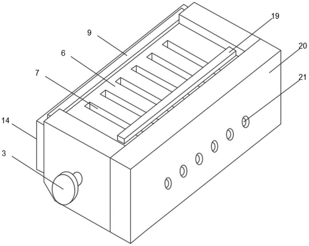
Fig. 7 shows the overall structure of the present invention.
FIG. 8 shows the structure of the cover;
in the figure: 1. a cover body; 2. a through hole; 3. a hand wheel; 4. a transmission prism block; 5. an air tap with a cover; 6. an upper support base; 7. a vertical cut; 8. a vertical cutter; 9. a first handle; 10. a slide bar; 11. a slide base; 12. a sliding sleeve; 13. a first return spring; 14. positioning seats; 15. positioning holes; 16. transversely cutting; 17. a transverse cutter; 18. a second return spring; 19. a second handle; 20. a side support base; 21. an observation hole; 22. a rotating frame; 23. a ridge groove; 24. a rotating ring; 25. a ring groove; 26. a main air pipe; 27. a cable trough; 28. an inner tank; 29. a cylinder; 30. an extrusion head; 31. a bronchus.
Detailed Description
The technical solutions in the embodiments of the present invention will be described clearly and completely with reference to the accompanying drawings in the embodiments of the present invention, and it is obvious that the described embodiments are only some embodiments of the present invention, not all embodiments. Based on the embodiments of the present invention, all other embodiments obtained by a person of ordinary skill in the art without creative efforts belong to the protection scope of the present invention.
As shown in fig. 8, the device for stripping a communication optical cable according to this embodiment includes a cover body 1, the cover body is a U-shaped structure integrally and includes a connecting plate, two ends of the connecting plate are respectively provided with a first side plate and a second side plate, the two side plates have the same shape, a chamfer is formed between a front end surface and a bottom surface of each side plate, the bottom surfaces of the side plates are supported on a workbench for supporting the whole device, the front end surface of the connecting plate coincides with the front end surfaces of the side plates, the front end surface of the connecting plate and the front end surfaces of the side plates together form a front end surface of the cover body, and rear end surfaces of the two side plates form a rear end surface of the cover body; wherein, both sides all correspond on the board and have seted up through-hole 2, wherein seted up annular 25 on the inside wall of curb plate two, through-hole, the annular on the board of both sides are all coaxial to be seted up.
As shown in fig. 3-5, a transverse cutting assembly is mounted on the front end face of the cover body, the transverse cutting assembly includes a positioning seat 14, the positioning seat is fixedly mounted on the front end face of the cover body connecting plate, a plurality of positioning holes 15 are spaced along the length direction of the connecting plate on the positioning seat, and the centers of the plurality of positioning holes are located on the same horizontal line and are arranged along the length direction of the positioning seat;
a transverse cutter 17 is connected to the top plate and the bottom plate on one side, close to the cover body, of the positioning seat, the transverse cutter is located between the positioning seat and the cover body, a first return spring 13 is arranged between the transverse cutter and the positioning seat, a first handle 9 is arranged on the other side, far away from the first return spring, of the transverse cutter, the first handles on the top plate and the bottom plate are pressed, and the two transverse cutters move relatively; the arc mouth has all been seted up corresponding to the position of locating hole 15 to one side edge of cross cut 17 keeping away from first in command 9, and the arc mouth position of cross cut 17 cuts the optical cable epidermis, sets for the size of cross cut, combines first in command 9 spacing for the cross cut can only cut the optical cable epidermis, can not cut inside cable, can avoid damaging the optic fibre like this.
As shown in fig. 3-5 and 7, a side supporting base 20 is fixedly connected to the rear end surface of the cover body, a plurality of observation holes 21 are formed in the side supporting base 20 at intervals along the length direction of the side supporting base, the centers of the observation holes are located on the same horizontal line, the observation holes are formed corresponding to the positioning holes, each positioning hole corresponds to one observation hole, and the optical cable to be peeled extends into the device through the positioning holes and extends out of the device through the observation holes.
As shown in fig. 1-3 and 6, a rotating assembly is arranged in the cover body, the rotating assembly comprises a rotating frame 22, an inward concave edge groove 23 is formed in the center of one end of the rotating frame, a cavity hole for installing a main air pipe 26 is formed in the center axis of the rotating frame, an air tap 5 with a cover is installed at one end, away from the edge groove, of the main air pipe, a rotating ring 24 is rotatably installed on the end face of one end, away from the edge groove, of the rotating frame, a rotating hand wheel 3 is inserted into a through hole of the first side plate, a transmission edge block 4 is arranged at one end, located in the cover body, of the rotating hand wheel, the transmission edge block is clamped in the edge groove of the rotating frame, and the rotating ring of the rotating frame is rotatably clamped in a ring groove of the second side plate to rotatably connect the rotating frame in the cover body;
a plurality of cable grooves 27 are uniformly formed in the outer surface of the rotating frame, each cable groove corresponds to one positioning hole and one observation hole, and an optical cable to be peeled extends into the cable groove through the positioning hole and extends out of the device through the observation hole; inside groove 28 has all been seted up on two inside walls in each cable groove, all be connected with cylinder 29 in each inside groove 28, every cylinder all communicates through bronchus 31 and main trachea, two cylinders in same cable groove are a set of, the telescopic link of two cylinders of same set sets up relatively, and all be connected with extrusion head 30 on the telescopic link, through opening the tape cover air cock and connect the air pump, make the air pump pass through main trachea 26, bronchus 31 is to the gas transmission in the cylinder, thereby be convenient for make the telescopic link of each cylinder 29 stretch out, it shifts out from inside groove 28 to drive the extrusion head 30 that corresponds, each extrusion head 30 is used for all being provided with anti-skidding line on the working face of centre gripping optical cable, increase extrusion head 30 is to the frictional force of cable epidermis, the fixed centre gripping of the optical cable that a set of relative setting will be cut by the crosscut sword is in cable groove 27.
As shown in fig. 1, 3-5, 7, a vertical cutting component is fixedly connected on the cover body above the rotating frame, the vertical cutting component comprises an upper supporting seat 6, the upper supporting seat 6 is fixedly connected on the top end of the cover body 1, a plurality of vertical cuts 7 are arranged at intervals on the top end of the upper supporting seat 6, when viewed from the upper side of the upper supporting seat, each vertical cut is rectangular, the vertical cuts are parallel to two side plates of the cover body and are perpendicular to a connecting plate of the cover body, the vertical cuts 7 are correspondingly arranged with cable grooves on the rotating frame, each vertical cut is communicated with the corresponding cable groove, a vertical cutting knife 8 is slidably connected in each vertical cut 7, the fixed end of each vertical cutting knife 8 is fixedly connected on a second handle 19, two ends of the second handle 19 are fixedly connected with a sliding rod 10, the sliding rods are vertically arranged with the upper supporting seat, the bottom side of the sliding rod 10 is connected with a sliding sleeve 12, a sliding seat 11 is arranged on the upper supporting seat, the bottom of sliding sleeve slides and sets up in slide 11, and the slide sets up with erecting the incision parallel arrangement, and the bottom of sliding sleeve is provided with second reset spring 18, through pushing down second handle 19, makes each perpendicular cutter 8 pierce downwards respectively in the optical cable epidermis that is located the cable groove, through following this second handle 19 along erecting incision 7 to collateral branch support seat 20 one side slip, makes perpendicular cutter 8 cut open the optical cable epidermis.
A transverse cut 16 is formed in one side, close to the cover body 1, of the positioning seat 14, the transverse cut 16, the positioning hole 15 and the inner side of the cover body 1 are communicated with each other, a transverse cutter 17 is arranged at the top and the bottom of the transverse cut 16, a first handle 9 is arranged at one end, far away from the transverse cut 16, of the transverse cutter 17, and the first handle 9 and the positioning seat 14 are fixedly connected with a first return spring 13 together.
When the device is used, the rotating frame 22 is firstly embedded into the inner bottom side of the cover body 1, the rotating ring 24 is embedded into the ring groove 25, then the hand wheel 3 is pushed into the cover body 1, the transmission edge block 4 is embedded into the edge groove 23 of the rotating frame 22, then, each optical cable to be peeled is respectively embedded into each positioning hole 15 of the positioning seat 14 until the optical cable extends into each cable groove 27 on the surface of the rotating frame 22 through the transverse cut 16, then extends out of the observation hole 21, and the transverse cutters 17 on the upper side and the lower side are used for performing annular cutting on each optical cable skin by extruding the first handle 9, so that the optical cable skin extending into the cover body 1 is cut apart from other parts; the vertical cutting knives 8 are respectively embedded into the cable skins which are circularly cut by extruding the second handle 19, then the second handle 19 is slid towards one side of the side supporting seat 20, so that the vertical cutting knives 8 can easily cut the cable skins along the vertical cuts 7, then the air pump is opened, the air pump is enabled to transmit air into the branch air pipes 31 through the main air pipe 26, so that the air cylinders 29 can conveniently drive the corresponding extrusion heads 30 to move out of the inner grooves 28, so that the cut cable skins can be clamped and limited in the cable grooves 27, then the hand wheel 3 is rotated, the transmission arris 4 drive the rotating frame 22 to rotate on the rotating ring 24, under the combined action of the rotating frame and the extrusion heads on the optical cable, the rotating frame 22 can pull off the cut skins, after the skins are peeled off, an operator can pull the optical cable towards one side of the positioning seat 14, so that the optical cable moves to one side of the cable grooves 27 close to the transverse cuts 16, then, the worker removes each peeled skin from the turret 22, and inserts the bare fiber protection sleeves into the bottom sides of the cable grooves 27, and the bare fiber protection sleeves can be respectively inserted into the surfaces of the optical fibers by rotating the handwheel 3, so as to protect the bare fibers.
The preferred embodiments of the present invention disclosed above are intended only to help illustrate the present invention. The preferred embodiments are not intended to be exhaustive or to limit the invention to the precise embodiments disclosed. Obviously, many modifications and variations are possible in light of the above teaching. The embodiments were chosen and described in order to best explain the principles of the invention and its practical applications, to thereby enable others skilled in the art to best understand the invention for and utilize the invention. The present invention is limited only by the claims and their full scope and equivalents.