Automatic mobile device of electric automobile chassis installation
Technical Field
The utility model relates to an automatic mobile device of electric automobile chassis installation belongs to electric automobile and makes technical field.
Background
The chassis structure of the automobile consists of a transmission system, a running system, a steering system and a braking system. The chassis is used for supporting and mounting the automobile engine and all parts and assemblies thereof to form the integral shape of the automobile, and receives the power of the engine to enable the automobile to move and ensure the normal running. For the automatic moving platform of the electric automobile chassis installation system, the main aim is to ensure that the chassis of the electric automobile can be automated in an assembly workshop, the assembly efficiency is greatly improved, the manufacturing cost is reduced, and the high precision of assembly between the chassis of the electric automobile and an automobile body is ensured. In order to automate a mobile platform in operation and improve the accuracy of the mobile platform, a PLC controller is generally used in the mobile platform.
However, several existing automobile chassis moving devices cannot stably provide required precision in a wide range of working conditions, so that connecting pieces in the electric automobile are unevenly worn due to the fact that the mounting precision between the frame and the chassis cannot meet the required requirement. Accordingly, there is a need for improvement in automotive chassis moving devices.
Disclosure of Invention
The utility model aims at providing an automatic mobile device of electric automobile chassis installation for solve the connecting piece among the current electric automobile because the installation accuracy can not reach required requirement and lead to the problem of inhomogeneous wearing and tearing between frame and the chassis, provide an electric automobile chassis installation.
The utility model discloses the technical scheme who realizes as follows, an automatic mobile device of electric automobile chassis installation, including electric automobile chassis, push rod elevating system, electromechanical drive mechanism, PLC controller, initiative hydraulic part, rack and pinion mechanism, drive assembly, electric liquid push rod, spill guide rail and DC motor.
The electric automobile chassis is arranged on a lifting plate of the push rod lifting mechanism through the gear rack mechanism; the driving hydraulic component is arranged in the push rod lifting mechanism; a bottom plate of the push rod lifting mechanism is provided with an electromechanical transmission mechanism, a PLC controller and a driving part; the automatic moving device can move relatively independently in three directions through the control of the PLC controller on the motor.
The push rod lifting mechanism comprises a driving hydraulic component and a driven connecting rod component, wherein the driving hydraulic component is arranged on a bottom plate of the driven connecting rod component and pushes the driven connecting rod component to move up and down.
The active hydraulic component comprises a transverse outer column, a hydraulic push rod, a hydraulic cylinder and an electro-hydraulic push rod; the electro-hydraulic push rod is arranged on the transverse outer column.
The driven connecting rod part comprises a lifting plate, a roller, a connecting rod, a rolling strip, a transverse inner column and a bottom plate; the telescopic lifting frames are formed by the idler wheels, the connecting rods, the rolling bars and the pin shafts, and the two same lifting frames are connected by the transverse inner column; the upper end of the lifting frame is provided with a horizontal lifting plate, and the upper end of the lifting frame is provided with a horizontal bottom plate; under the push of the electro-hydraulic push rod, the push rod lifting mechanism can drive the device to vertically move up and down.
The electro-hydraulic push rod is a novel flexible transmission mechanism integrating mechanical, electrical and hydraulic functions, pressure oil is output by the motor in a positive and negative rotation mode through the bidirectional hydraulic pump, the pressure oil is sent to the oil cylinder through the hydraulic control valve, reciprocating motion of the piston rod is achieved, and therefore reciprocating up and down movement of the lifting plate is achieved.
One end of the connecting rod is fixed by a fixed support, and the other end of the connecting rod is provided with a roller which can convert sliding friction into rolling friction so as to improve the mechanical efficiency of the mechanism.
The gear rack mechanism comprises an alternating current motor, an output shaft, an output gear, a rack, a cross bar, a pulley shaft and a first pulley, and is arranged between the supporting plate and the lifting plate; the alternating current motor is fixed at the right lower part of the support plate, an output shaft of the alternating current motor penetrates through the support plate, and an output gear connected through a key is arranged at the other end of the output shaft; the rack and the cross bar are equal in length and parallel to each other, and are fixedly connected to the lifting plate through bolts, and meanwhile, the output gear and the rack can be accurately meshed; the rack is only provided with teeth on the moving part, and a convex strip and a groove are processed on the other side of the rack without the teeth, so that the first pulley is in surface contact with the convex strip; the four first pulleys are respectively arranged at the outer sides of the rack and the transverse bar, and pulley shafts of the four first pulleys are fixedly arranged on the lower bottom surface of the supporting plate; the alternating current motor drives the output gear to move on the rack, so that the supporting plate driving device can linearly move in the left-right horizontal direction.
An input gear shaft of the gear rack mechanism penetrates through the supporting plate, a gear and a rack can be accurately meshed, and the gear rack mechanism is provided with a limiting device to prevent misoperation.
The electromechanical transmission mechanism comprises a driving shaft, a driven shaft, a belt, a driving part, a direct current motor and a PLC (programmable logic controller);
the two direct current motors are respectively arranged at two ends of the top surface of the square bottom plate, and the PLC is arranged on the bottom plate between the two direct current motors; one end of the driving shaft is connected with the direct current motor and driven by the direct current motor, and the other end of the driving shaft is connected with the belt wheel through a key; driving components are respectively arranged at four corners of the bottom surface of the bottom plate; the driving part comprises a pair of driving wheel structures and a pair of driven wheel structures; the driving wheel structure comprises a driving shaft, a first driving bracket, a second pulley and a belt pulley; the first driving support is arranged on the bottom plate below the direct current motor, the driving shaft is arranged on the driving support, and the second pulley and the belt pulley are arranged on the driving shaft; the belt pulley is connected with a belt pulley on the driving shaft through a belt. The driven wheel structure comprises a driven shaft, a second driving support and a second pulley, the driven shaft is installed on the second driving support, the second pulley is installed on the driven shaft, and the second driving support is installed at the other two corners of the bottom surface of the bottom plate and corresponds to the first driving support of the driving wheel structure. The four second pulleys are placed on the concave guide rails, and the two parallel concave guide rails are fixedly arranged on the workbench; under the drive of the DC motor, the bottom plate drives the device to linearly move along the concave guide rail in the front-back direction.
The PLC is respectively and electrically connected with the alternating current motor, the direct current motor and the electro-hydraulic push rod through leads; the automatic moving device can move relatively independently in three directions through the control of the PLC controller on the motor.
The utility model has the advantages that the automatic moving device can move relatively independently in the up-down, left-right and front-back directions through the control of the PLC controller to the motor; the automatic assembling method is easy to realize automation, the assembling precision and the assembling efficiency are obviously improved, the reject ratio of the electric automobile chassis in the assembling process is greatly reduced, and the purpose of saving the manufacturing cost is achieved.
Drawings
Fig. 1 is a schematic structural diagram of an embodiment of the present invention;
FIG. 2 is a schematic perspective view of an electric vehicle chassis according to an embodiment;
FIG. 3 is a schematic structural diagram of a rack and pinion mechanism according to an embodiment;
FIG. 4 is a schematic view of an embodiment of a lift mechanism;
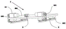
FIG. 5 is a schematic structural diagram of an electromechanical transmission of an embodiment;
FIG. 6a is a perspective view of an electro-hydraulic push rod of an embodiment;
FIG. 6b is a longitudinal cross-sectional view of an electro-hydraulic pushrod according to an embodiment;
FIG. 7 is a schematic structural diagram of the active component of the embodiment of FIG. 5;
in the figure, 1 is an automatic moving device; 2 is an electric automobile chassis; 3 is a gear rack mechanism; 4 is a push rod lifting mechanism; 5 is an electromechanical transmission mechanism; 6 is an active hydraulic component; 7 is a driving part; 8 is a concave guide rail; 9 is a PLC controller; 10 is a DC motor; 11 is an electro-hydraulic push rod; 12 is a fixed support; 201 is an electric drive module; 202 is a shock absorber; 203 is a brake disc; 204 is a half shaft; 205 is a frame; 206 is a cross arm; 207 is a damping spring; 208 is a supporting plate; 301 is a pulley shaft; 302 is an AC motor; 303 is an output shaft; 304 is an output gear; 305 is a rack; 306 is a horizontal bar; 307 is a first pulley; 401 is a lifting plate; 402 is a roller; 403 is a connecting rod; 404 is a rolling bar; 405 is a transverse inner column; 406 is a backplane; 407 is a xiaozhou; 501 is a driving shaft; 502 is a driven shaft; 503 is a belt; 601 is a transverse outer column; 602 is a hydraulic push rod; 603 is a hydraulic cylinder; 701 is a driving shaft; 702 is a first drive bracket; 703 is a belt pulley; and 704 is a second pulley.
Detailed Description
The following describes embodiments of the present invention in further detail with reference to the accompanying drawings.
As shown in fig. 1 and 2, the automatic moving device for chassis installation of an electric vehicle in the present embodiment includes an electric vehicle chassis 2, a rack and pinion mechanism 3, a driving hydraulic component 6 and a driven link component 4 in a push rod lifting mechanism, and an electromechanical transmission mechanism 5.
The electric automobile chassis 2 is arranged right above the supporting plate 208, the middle part of the automobile chassis 2 is an electric driving module 201, a motor, a fixed speed ratio reducer and a differential mechanism are integrated into a whole, two half shafts 204 are connected with two brake discs 203, and the electric automobile chassis further comprises a shock absorber 202, a shock absorption spring 207 and a cross arm 206, so that the vibration of the electric automobile is attenuated, and the service life of the electric automobile is prolonged.
As shown in fig. 3, the rack and pinion mechanism 3 of the present embodiment is disposed between the support plate 208 and the lifting plate 401 via bolt connection.
The rack-and-pinion mechanism 3 includes an ac motor 302, an output shaft 303, an output gear 304, and a rack 305.
The ac motor 302 is fixed to the lower right of the support plate 208, and an output shaft 303 thereof penetrates the support plate 208, and an output gear 304 connected by a key is provided at the other end of the output shaft 303.
The rack 305 is fixed on the lifting plate 401 through bolt connection, and the gear 304 and the rack 305 can be accurately meshed. In particular, in order to prevent improper PLC control, the mechanism is limited, wherein the rack 305 is only toothed at the moving part, and a convex strip and a concave groove are machined on the other side of the rack 305 without teeth, so that the first pulley 307 is in surface contact with the convex strip. The upper ends of the four straight shafts 301 are fixed below the lifting plate 401, the lower ends of the four straight shafts are in interference fit with the inner ring of the bearing, and the inner ring of the first pulley 307 is in clearance fit with the outer ring of the bearing, so that the friction resistance can be fully reduced, and the platform can move more stably.
The working principle of the gear rack mechanism is as follows: when the electric automobile chassis 2 needs to move left and right due to inaccurate positioning in the assembling process, the PLC controller controls the forward and reverse rotation of the ac motor 302, thereby controlling the forward and reverse rotation of the output gear 303. Because the rack 305 is fixed, the reaction force generated by the meshing of the rack 305 with the gear 303 moves the support plate 208 in a desired direction.
As shown in fig. 4, 6a and 6b, the ram lift mechanism of the present embodiment includes a driving hydraulic part 6 and a driven link part 4, which is a middle part of the automatic moving platform 1 and can lift and lower the chassis of the vehicle.
The hydraulic component mainly comprises a transverse outer column 601 and an electro-hydraulic push rod 11.
The driven link member 4 is mainly composed of a lifting plate 401, a link 403, and a base plate 406.
The electro-hydraulic push rod 11 is a novel flexible transmission mechanism integrating mechanical, electrical and hydraulic functions, and the motor drives the bidirectional hydraulic pump to output pressure oil in a positive and negative mode through positive and negative rotation and sends the pressure oil to the hydraulic cylinder 603 through the hydraulic control valve to realize the reciprocating motion of the hydraulic push rod 602. The cross section of the transverse outer column 601 is of a water drop type, and the transverse outer column has enough strength and rigidity to bear the force transmitted by the electro-hydraulic push rod. In order to improve the strength and rigidity of the driven link member 4, a lateral inner post 405 is intentionally added between the left and right links 403, wherein the inner post 405 penetrates the lateral outer post 601.
4 links 403 are symmetrically arranged on the bottom plate 406 from left to right, and the link 403 on one side is connected with the link 403 through a pin 407, so that the lifting height of the automatic moving device can be increased. The push rod lifting mechanism can have violent friction and abrasion in the repeated lifting process, for this reason, this embodiment installs gyro wheel 402 and rolling strip 404 additional, gyro wheel 402 contacts with rolling strip 404, goes up rolling strip 404 and passes through the bolt fastening at the left and right both ends of lifter plate 401 bottom surface, and lower rolling strip 404 passes through the bolt fastening at the left and right both ends of bottom plate 406 top surface.
The top surface of the base plate 406 also has two fixed supports 12 in line with the roller bar 404, and the bottom surface of the lifter plate also has two fixed supports 12, which perform a specific raising and lowering function.
The working principle of the push rod lifting mechanism is as follows: when the chassis needs to move up or down in the installation process, the PLC controls the motor in the electro-hydraulic push rod 11 to rotate forward and backward, so that the hydraulic push rod 602 is controlled to work in and unload, and the lifting plate 401 and the electric vehicle chassis 2 above the lifting plate are lifted or lowered by using the two connecting rods 403 as the executing mechanisms.
As shown in fig. 5 and 7, the electromechanical transmission mechanism 5 of the present embodiment is formed by a drive shaft 501, a driven shaft 502, a belt 503, a drive member 7, a dc motor 10, a PLC controller 9, and the like, at the bottom of the automatic moving platform 1. Specifically, the dc motor 10 is mounted on both ends of the top surface of the base plate 401, and the drive shaft 501 is provided to provide a driving force from a source.
The two direct current motors 10 are respectively arranged at two ends of the top surface of the square bottom plate 406, and the PLC 10 is arranged on the bottom plate 406 between the two direct current motors 10; one end of the drive shaft 501 is connected to the dc motor 10, and is driven by the dc motor 10, and the other end is connected to the pulley by a key. Drive members 7 are attached to four corners of the bottom surface of the bottom plate 406.
The drive member 7 includes a pair of driving wheel structures and a pair of driven wheel structures.
The driving wheel structure comprises a driving shaft 701, a first driving support 702, a second pulley 704 and a belt pulley 703, wherein the first driving support 702 is installed on a bottom plate below the direct current motor 10, the driving shaft 701 is installed on the first driving support 702, the second pulley 704 and the belt pulley 703 are installed on the driving shaft 701, and the belt pulley 703 is connected with the belt pulley 703 on the driving shaft 701 through a belt 503.
The driven wheel structure includes a driven shaft 502, a second drive bracket, and a second pulley 704; the driven shaft 502 is mounted on a second driving bracket, a second pulley 704 is mounted on the driven shaft 502, and the second driving bracket is mounted at the other two corners of the bottom surface of the bottom plate 406, corresponding to the first driving bracket 702 of the driving wheel structure.
Four second pulleys 704 are placed on the concave guide rails 8, and two mutually parallel concave guide rails 8 are fixedly arranged on the workbench; under the driving of the dc motor 10, the bottom plate 406 drives the device to move linearly in the front-back direction along the concave guide rail 8.
The electromechanical transmission mechanism 5 specifically works according to the following principle: when the automatic moving platform 1 needs to advance or retreat, the PLC controller 9 controls the forward and reverse rotation of the driving shaft 501 of the dc motor 10, so that the driving force is transmitted to the driven shaft 502 through belt transmission, and the forward and reverse rotation of the driving wheel is driven through the forward and reverse rotation of the driven shaft 502, thereby realizing the advance and retreat of the automatic moving platform 1.
This embodiment is controlled all motors through PLC controller 9 for when the electric automobile chassis was assembled, the motor among the automatic moving device independently turned to according to required under PLC controller 9's the effect and carries out corotation or reversal, thereby drives automatic moving platform 1 and moves according to required moving direction, makes this automatic moving platform 1 not only can improve assembly efficiency by a wide margin, can also guarantee the high accuracy of product assembly production.