Portable soil pollution is prosthetic devices on spot
Technical Field
The utility model relates to a soil remediation field especially relates to a portable soil pollution is prosthetic devices on spot.
Background
Soil remediation is a technical measure to restore normal function to contaminated soil. In the soil remediation industry, the existing soil remediation technologies can be more than one hundred, the common technologies can be more than ten, and the existing soil remediation technologies can be roughly divided into three methods, namely physical methods, chemical methods and biological methods. Since the 80 s in the 20 th century, many countries in the world, especially developed countries, have established and developed contaminated soil remediation and remediation programs, thus forming an emerging soil remediation industry.
This application improves under prior art, and among the prior art, current soil prosthetic devices can not carry out the restoration on the spot to polluting soil, and remediation efficiency is lower.
SUMMERY OF THE UTILITY MODEL
The utility model aims at solving the defects existing in the prior art and providing a mobile soil pollution on-site repairing device.
In order to achieve the above purpose, the utility model adopts the following technical scheme:
a mobile soil pollution in-situ remediation device, which comprises a device body, wherein a medicament box is fixedly connected in the device body, a stirring shaft which is rotationally connected with the inner wall of the bottom of the device body is rotationally connected in the drug box, the bottom of one side of the drug box is fixedly connected with a conduit, the bottom end of the guide pipe is fixedly connected with a water pump fixedly connected with the device body, the water outlet of the water pump is fixedly connected with a spraying pipe, a driving shaft is arranged on one side of the stirring shaft away from the guide pipe, the inner wall of the bottom of the driving shaft is movably connected with a connecting shaft, the outer wall of the connecting shaft is rotationally connected with a mounting rack which is connected with the device body in a sliding way, the inner wall of the mounting rack is rotationally connected with a driven shaft, the fixed cover of driven shaft outer wall has connect the dish that loosens the soil of multiunit equidistance distribution, the pole that loosens the soil of the dish outer wall of loosening the soil that distributes along its circumferencial direction fixedly connected with multiunit equidistance.
As a further description of the above technical solution: the (mixing) shaft stretches into the puddler of the one end outer wall fixedly connected with symmetric distribution of chemical tank, the fixed cover of the one end outer wall that the (mixing) shaft stretches out the chemical tank bottom has connect first belt pulley, the fixed cover of driving shaft outer wall has connect the second belt pulley, and is connected through the belt between second belt pulley and the first belt pulley, chemical tank one side outer wall fixedly connected with motor, and motor output shaft and driving shaft fixed connection.
As a further description of the above technical solution: the inner wall of the driving shaft is fixedly connected with symmetrically distributed slide bars, symmetrically distributed sliding grooves are formed in two sides of the connecting shaft, and the sliding grooves are matched with the connecting shaft.
As a further description of the above technical solution: the outer wall of the bottom end of the connecting shaft is fixedly sleeved with a first bevel gear, the outer wall of the driven shaft is fixedly sleeved with a second bevel gear, and the second bevel gear is meshed with the first bevel gear.
As a further description of the above technical solution: the device comprises a mounting frame, wherein supporting plates are fixedly connected to two sides of the mounting frame, the supporting plates are symmetrically distributed, electric telescopic rods are fixedly connected to the bottom of the device body, the electric telescopic rods are symmetrically distributed, and the driving ends of the electric telescopic rods are fixedly connected with the supporting plates.
As a further description of the above technical solution: the device comprises a device body and is characterized in that a tool bin is arranged on one side of the device body, a bin door is hinged to the inner wall of one side, away from a chemical box, of the tool bin, and walking wheels which are symmetrically distributed are fixedly arranged at the bottom of the device body.
The utility model discloses following beneficial effect has:
1. when the utility model is used, the body of the pushing device moves, the motor is started, the motor output shaft rotates to drive the driving shaft to rotate, the driving shaft rotates to drive the connecting shaft to rotate, the connecting shaft rotates to drive the first bevel gear to rotate, the first bevel gear rotates to drive the second bevel gear to rotate and further drive the driven shaft to rotate, the driven shaft rotates to drive the soil loosening disc to rotate and further drive the soil loosening rod to rotate to loosen soil, the driving shaft rotates to drive the second belt pulley to rotate, the second belt pulley rotates through the belt first belt pulley, the first belt pulley rotates to drive the stirring shaft to rotate, the stirring shaft rotates to drive the stirring rod to rotate to stir the repairing agent in the agent box to avoid the agent in the agent box from precipitating, the water pump is started, the water pump conveys the agent in the agent box to the spray pipe through the guide pipe, the spray pipe sprays the agent to the soil after loosening soil to repair the soil, the contaminated soil is repaired on site, and the soil repairing efficiency is improved.
2. The utility model discloses when the degree of depth of loosening the soil of pole that loosens the soil in well needs to be adjusted, start electric telescopic handle, the electric telescopic handle drive end drives the extension board and removes and then makes the mounting bracket remove, and the mounting bracket removes the in-process, and the connecting axle removes, and the draw runner plays the direction to the removal of connecting axle, later through the cooperation of spout and draw runner, when the driving shaft rotates, the connecting axle still can rotate, is convenient for adjust the degree of depth of loosening the soil of the pole that loosens the soil.
Drawings
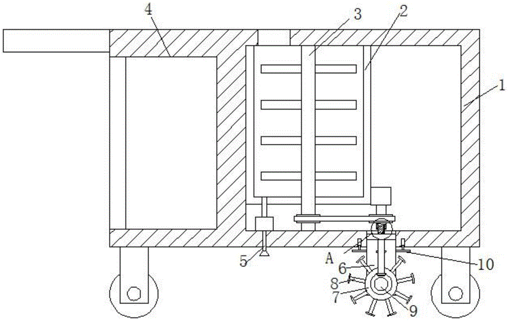
Fig. 1 is a schematic structural view of a mobile soil pollution in-situ remediation device provided by the utility model;
fig. 2 is an enlarged schematic structural view of a point a in fig. 1 according to the present invention;
fig. 3 is the utility model provides a portable soil pollution is prosthetic devices's on spot loosening pan installation schematic diagram.
Illustration of the drawings:
1-device body, 2-chemical box, 3-stirring shaft, 4-tool bin, 5-spraying pipe, 6-mounting rack, 7-soil loosening disc, 8-soil loosening rod, 9-driven shaft, 10-support plate, 11-driving shaft, 12-connecting shaft, 13-sliding groove and 14-sliding strip.
Detailed Description
The technical solutions in the embodiments of the present invention will be described clearly and completely with reference to the accompanying drawings in the embodiments of the present invention, and it is obvious that the described embodiments are only some embodiments of the present invention, not all embodiments. Based on the embodiments in the present invention, all other embodiments obtained by a person skilled in the art without creative work belong to the protection scope of the present invention.
In the description of the present invention, it should be noted that the terms "center", "upper", "lower", "left", "right", "vertical", "horizontal", "inner", "outer", and the like indicate orientations or positional relationships based on the orientations or positional relationships shown in the drawings, and are only for convenience of description and simplification of description, but do not indicate or imply that the device or element referred to must have a specific orientation, be constructed and operated in a specific orientation, and thus, should not be construed as limiting the present invention; the terms "first," "second," and "third" are used for descriptive purposes only and are not to be construed as indicating or implying relative importance, and furthermore, unless otherwise explicitly stated or limited, the terms "mounted," "connected," and "connected" are to be construed broadly and may be, for example, fixedly connected, detachably connected, or integrally connected; can be mechanically or electrically connected; they may be connected directly or indirectly through intervening media, or they may be interconnected between two elements. The specific meaning of the above terms in the present invention can be understood in specific cases to those skilled in the art.
Referring to fig. 1-3, the utility model provides a portable soil pollution repair device on spot, including device body 1, tool bin 4 is equipped on one side of device body 1, tool bin 4 is articulated with the door on one side of inner wall of the tool bin 4 far away from chemical tank 2, the bottom of device body 1 is fixedly equipped with symmetrically distributed walking wheels, chemical tank 2 is fixedly connected in device body 1, chemical tank 2 is rotatably connected with stirring shaft 3 rotatably connected with the inner wall of the bottom of device body 1, stirring shaft 3 is fixedly connected with symmetrically distributed stirring rods on the outer wall of one end extending into chemical tank 2, first belt pulley is fixedly sleeved on the outer wall of one end of stirring shaft 3 extending out of the bottom of chemical tank 2, second belt pulley is fixedly sleeved on the outer wall of driving shaft 11, and the second belt pulley is connected with the first belt pulley through the belt, the outer wall of one side of chemical tank 2 is fixedly connected with the motor, and the motor output shaft is fixedly connected with driving shaft 11, the bottom of one side of the chemical box 2 is fixedly connected with a guide pipe, the bottom of the guide pipe is fixedly connected with a water pump fixedly connected with the device body 1, a water outlet of the water pump is fixedly connected with a spray pipe 5, one side of the stirring shaft 3 far away from the guide pipe is provided with a driving shaft 11, the inner wall of the driving shaft 11 is fixedly connected with symmetrically distributed slide bars 14, two sides of a connecting shaft 12 are provided with symmetrically distributed chutes 13, the chutes 13 are matched with the connecting shaft 12, the inner wall of the bottom of the driving shaft 11 is movably connected with the connecting shaft 12, the outer wall of the bottom end of the connecting shaft 12 is fixedly sleeved with a first bevel gear, the outer wall of the driven shaft 9 is fixedly sleeved with a second bevel gear, the second bevel gear is meshed with the first bevel gear, the outer wall of the connecting shaft 12 is rotatably connected with a mounting frame 6 which is slidably connected with the device body 1, two sides of the mounting frame 6 are fixedly connected with symmetrically distributed support plates 10, and the bottom of the device body 1 is fixedly connected with symmetrically distributed electric telescopic rods, and electric telescopic handle drive end and extension board 10 fixed connection, 6 inner walls of mounting bracket rotate and are connected with driven shaft 9, and the fixed cover of driven shaft 9 outer wall has connect the dish 7 that loosens the soil that the multiunit equidistance distributes, loosens the soil and coils 7 outer wall along its circumferencial direction fixedly connected with the pole 8 that loosens the soil that the multiunit equidistance distributes.
The working principle is as follows:
in the application, when the device is used, the device body 1 is pushed to move, the motor is started, the motor output shaft rotates to drive the driving shaft 11 to rotate, the driving shaft 11 rotates to drive the connecting shaft 12 to rotate, the connecting shaft 12 rotates to drive the first bevel gear to rotate, the first bevel gear rotates to drive the second bevel gear to rotate and further drive the driven shaft 9 to rotate, the driven shaft 9 rotates to drive the soil loosening disc 7 to rotate and further drive the soil loosening rod 8 to rotate to loosen soil, the driving shaft 11 rotates and simultaneously drives the second belt pulley to rotate, the second belt pulley rotates through the first belt pulley of the belt, the first belt pulley rotates to drive the stirring shaft 3 to rotate, the stirring shaft 3 rotates to drive the stirring rod to rotate to stir the repairing agent in the agent box 2 so as to avoid the agent in the agent box 2 from precipitating, the water pump is started, the agent in the agent box 2 is conveyed to the spraying pipe 5 through the guide pipe by the water pump, the spraying pipe 5 sprays the agent to the soil after loosening soil to repair the soil, the in-situ remediation of the polluted soil is realized, and the remediation efficiency of the soil is improved;
in this application, when the depth of the soil of pole 8 that loosens the soil needs to be adjusted, start electric telescopic handle, electric telescopic handle drive end drives extension board 10 and removes and then makes mounting bracket 6 remove, and mounting bracket 6 removes the in-process, and connecting axle 12 removes, and draw runner 14 plays the direction to the removal of connecting axle 12, later through spout 13 and the cooperation of draw runner 14, when driving shaft 11 rotates, connecting axle 12 still can rotate, is convenient for adjust the depth of the soil that loosens of pole 8 that loosens the soil.
Finally, it should be noted that: although the present invention has been described in detail with reference to the foregoing embodiments, it will be apparent to those skilled in the art that modifications and variations can be made in the embodiments or in part of the technical features of the embodiments without departing from the spirit and the scope of the invention.