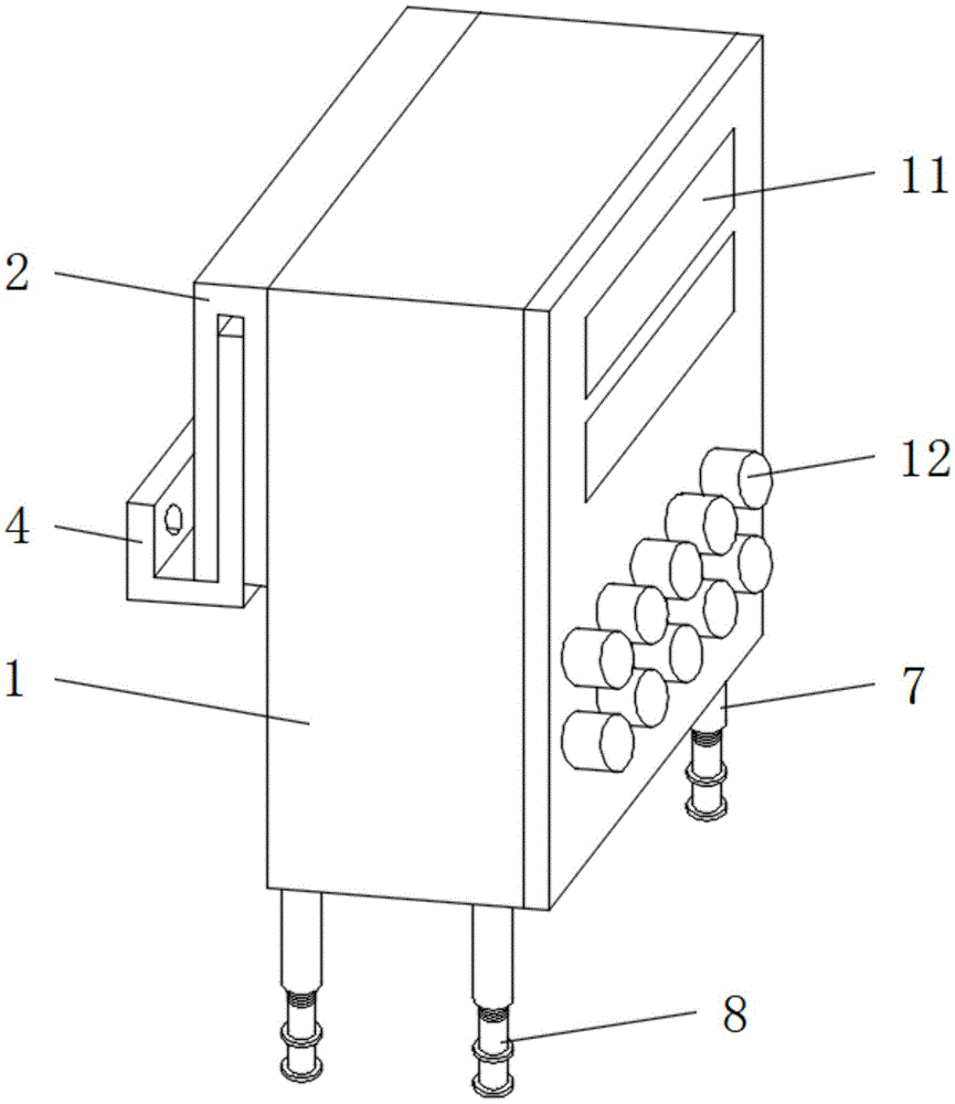
Novel illumination socket box
Technical Field
The utility model relates to an electric power field, in particular to novel illumination socket case.
Background
The lighting socket box mainly comprises an engineering plastic box body, an industrial plug, an industrial socket and an electrical appliance element, has the advantages of attractive appearance and wide application range, and has the functions of overload protection, short circuit protection, leakage protection and the like; the existing lighting socket box has certain defects when in use, firstly, when the socket box is used for a long time and needs to be fixed on a wall surface, the fixing process is troublesome and difficult to detach, and secondly, when the socket box is positioned at the place with uneven ground, the socket box is easy to overturn and damage the socket box, so that a novel lighting socket box is provided.
SUMMERY OF THE UTILITY MODEL
A primary object of the present invention is to provide a novel lighting socket box, which can effectively solve the problems of the background art.
In order to achieve the above purpose, the utility model adopts the following technical scheme:
the utility model provides a novel illumination socket case, includes the socket case body, the surface of socket case body is provided with the fixed plate, the surface of fixed plate is provided with the draw-in groove, one side of fixed plate is provided with the fixed block, the one end surface of fixed block is provided with the connecting plate, the surface of fixed block is provided with the connecting hole, the lower extreme surface of socket case body is provided with fixed sleeve, fixed sleeve's lower extreme is provided with the screw thread support column, the lower extreme surface of screw thread support column is provided with the slipmat, the surface of screw thread support column is provided with the adjustment handle.
Preferably, the socket box body is fixedly connected with the fixing plate, the cross section of the fixing block is L-shaped, the fixing block is fixedly connected with the connecting plate, and the connecting plate is matched with the clamping groove.
By adopting the technical scheme, the following technical effects can be achieved: the socket box is convenient to fix and is convenient to disassemble.
Preferably, the connecting plate is movably connected with the fixing plate, the fixing block and the connecting plate are made of alloy materials, and the connecting holes are located on the outer surface of the fixing block and are arranged in an array mode.
By adopting the technical scheme, the following technical effects can be achieved: the alloy parts have prolonged service life.
Preferably, be fixed connection between socket case body and the fixed sleeving, the lower extreme that the fixed sleeving is located socket case body is close to the corner and is the array and arranges, screw thread support column and fixed sleeving match, be swing joint between screw thread support column and the fixed sleeving.
By adopting the technical scheme, the following technical effects can be achieved: thereby carry out the leveling to the socket case through the height of adjusting the screw thread support column.
Preferably, the threaded support column and the non-slip mat are fixedly connected through glue, the non-slip mat is made of rubber, and the threaded support column and the adjusting handle are fixedly connected.
By adopting the technical scheme, the following technical effects can be achieved: the non-slip mat improves the friction force and enhances the stability.
Preferably, the outer surface of the socket box body is provided with an observation window, the lower end of the observation window is provided with a power jack, the outer surface of the lower end of the socket box body is provided with a threading hole, and the socket box body is movably connected with the observation window and the power jack.
By adopting the technical scheme, the following technical effects can be achieved: the socket box body is movably connected with part of components, so that the socket box is convenient to mount and dismount.
Compared with the prior art, the utility model discloses following beneficial effect has: the novel lighting socket box is provided with the fixing plate, the fixing block, the connecting plate and the connecting hole, when the socket box needs to be fixed on a wall surface after long-term use, a user firstly utilizes the existing fixing bolt to penetrate through the connecting hole to fix the fixing block on a designated position on the wall surface, then the fixing plate is connected with the connecting plate to enable the connecting plate to be positioned inside the groove to finish the fixing of the socket box, when the socket box needs to be taken down, the user integrally lifts the socket box upwards to enable the connecting plate to be separated from the fixing plate to finish the dismounting, the mounting and the dismounting of the socket box are convenient, the socket box is firstly placed on the ground by arranging the fixing sleeve, the threaded support column and the non-slip mat, when the socket box is placed in a place with uneven ground, the socket box is firstly placed on the ground, then the threaded support column is rotated by rotating the adjusting handle to level the socket box, simultaneously the slipmat has improved frictional force, and the placing that the socket box can be steady improves the steadiness subaerial, and the result of use is better for traditional mode.
Drawings
Fig. 1 is a schematic view of the overall structure of a novel lighting socket box of the present invention;
fig. 2 is a schematic view of the novel illumination socket box of the present invention for disassembling the fixing plate and the connecting plate;
fig. 3 is a schematic view of the novel illumination socket box of the present invention, illustrating the disassembly of the fixing tube and the threaded support post;
fig. 4 is a side view of the novel lighting socket box of the present invention.
In the figure: 1. a socket box body; 2. a fixing plate; 3. a card slot; 4. a fixed block; 5. a connecting plate; 6. connecting holes; 7. fixing the sleeve; 8. a threaded support post; 9. a non-slip mat; 10. an adjusting handle; 11. an observation window; 12. a power jack; 13. and (6) threading holes.
Detailed Description
In order to make the technical means, creation features, achievement purposes and functions of the present invention easy to understand, the present invention is further described below with reference to the following embodiments.
As shown in fig. 1-4, a novel lighting socket box comprises a socket box body 1, wherein a fixing plate 2 is arranged on the outer surface of the socket box body 1, a clamping groove 3 is formed in the outer surface of the fixing plate 2, a fixing block 4 is arranged on one side of the fixing plate 2, a connecting plate 5 is arranged on the outer surface of one end of the fixing block 4, a connecting hole 6 is formed in the outer surface of the fixing block 4, a fixing sleeve 7 is arranged on the outer surface of the lower end of the socket box body 1, a threaded support column 8 is arranged at the lower end of the fixing sleeve 7, an anti-slip pad 9 is arranged on the outer surface of the lower end of the threaded support column 8, and an adjusting handle 10 is arranged on the outer surface of the threaded support column 8.
Be fixed connection between socket case body 1 and fixed plate 2, the cross-section of fixed block 4 is "L" form, is fixed connection between fixed block 4 and the connecting plate 5, and connecting plate 5 and draw-in groove 3 phase-match are comparatively convenient when needs fix the socket case on the wall, and convenient to detach.
The connecting plate 5 is movably connected with the fixing plate 2, the fixing block 4 and the connecting plate 5 are made of alloy materials, the connecting holes 6 are located on the outer surface of the fixing block 4 and are arranged in an array mode, and part of components are made of alloy materials, so that the service life is prolonged.
Be fixed connection between socket case body 1 and the fixed sleeving 7, fixed sleeving 7 is located socket case body 1's lower extreme and is close to the corner and be the array and arrange, and screw support column 8 and fixed sleeving 7 phase-match are swing joint between screw support column 8 and the fixed sleeving 7, thereby leveling the socket case through the height of adjusting screw support column 8, improve socket case body 1's stability.
Form fixed connection through glue between screw support column 8 and the slipmat 9, the slipmat 9 is made for the rubber material, is fixed connection between screw support column 8 and the regulation handle 10, and the slipmat 9 of rubber material has improved frictional force to improve stability.
The outer surface of the socket box body 1 is provided with an observation window 11, the lower end of the observation window 11 is provided with a power jack 12, the outer surface of the lower end of the socket box body 1 is provided with a threading hole 13, the socket box body 1, the observation window 11 and the power jack 12 are movably connected, the socket box body 1 and part of parts are movably connected, and the damaged parts are convenient to detach, overhaul or replace.
It should be noted that the utility model relates to a novel lighting socket box, when the socket box needs to be fixed on the wall surface for a long time, the user needs to use the existing fixing bolt to pass through the connecting hole 6 to install the fixing block 4 to the designated position, then the clamping groove 3 on the outer surface of the fixing plate 2 is connected with the connecting plate 5 to complete the fixing of the socket box, when the socket box needs to be taken down, the user integrally lifts the socket box upwards to separate the connecting plate 5 from the fixing plate 2 to complete the disassembly, the installation and disassembly of the socket box are convenient, the socket box is convenient to fix, when the socket box needs to be placed on uneven ground, the socket box is firstly placed on the ground, the anti-skid pad 9 is contacted with the ground, then the threaded support column 8 is rotated by rotating the adjusting handle 10, the socket box is in the flat state, the socket box can be stably placed on the ground, meanwhile, the anti-slip mat 9 improves the friction force and the stability and is practical.
The basic principles and the main features of the invention and the advantages of the invention have been shown and described above. It will be understood by those skilled in the art that the present invention is not limited to the above embodiments, and that the foregoing embodiments and descriptions are provided only to illustrate the principles of the present invention without departing from the spirit and scope of the present invention. The scope of the invention is defined by the appended claims and equivalents thereof.