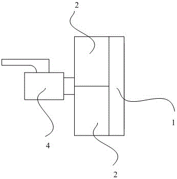
Pressure test tool for groove type pipe fitting
Technical Field
The utility model relates to the technical field of machinery, especially, relate to a slot type pressure test frock for pipe fitting.
Background
The transmission tool for long-distance transmission of liquid or gas is widely used, the transmission pipeline is formed by connecting a plurality of steel pipes, two steel pipes are connected through a connector, and a valve is arranged between the steel pipes according to requirements. The steel pipes and the valves are directly connected by generally adopting a pipeline sealing connector (such as CN 210800309U). However, steel pipes or valves are often subjected to pressure testing before use. Taking a steel pipe as an example, two ends of the steel pipe are connected with a test tool through a pipeline sealing connector to ensure sealing connection, and then high-pressure liquid is injected into the steel pipe. During the connection operation, the assembly of the sealing connector needs to be completed, the operation process is complicated, and the labor intensity of workers is high. How to design a simple structure and conveniently assemble the technique of test is the utility model discloses the technical problem that will solve.
SUMMERY OF THE UTILITY MODEL
The utility model discloses the technical problem that will solve is: the utility model provides a pressure test frock for slot type pipe fitting realizes simplifying the structural style of pressure test frock for slot type pipe fitting to make things convenient for quick convenient completion equipment of operating personnel, in order to improve efficiency of software testing.
The utility model provides a technical scheme is, a groove type pressure test frock for pipe fitting for the test tube pressure measurement that awaits measuring, wherein, the outside of test tube is provided with the slot, including go-between, two cutting ferrule, end cover and high-pressure ball valve, the inner periphery of go-between forms the internal thread, the cross-section of cutting ferrule is semi-circular structure, the inner wall of cutting ferrule is provided with the arc draw-in groove, the outer wall of cutting ferrule is provided with the external screw thread, the inner wall of cutting ferrule still is provided with protruding arc rib, be provided with the connector on the end cover of sealing; the high-pressure ball valve is connected to the connecting port in a sealing mode, the sealing end cover is located between the two clamping sleeves and inserted into the arc-shaped clamping groove, the two clamping sleeves are connected in a butt joint mode, and the connecting ring is connected to the outer portions of the two clamping sleeves in a threaded mode.
Furthermore, the edge of the sealing end cover is provided with an annular flange.
Furthermore, the sealing device also comprises a sealing ring which is positioned in a space formed by the annular flanging and is attached to the inner wall of the sealing end cover.
Furthermore, the section of the sealing ring is of a V-shaped structure.
Further, the inner wall of the cutting sleeve is provided with a plurality of arc-shaped ribs.
Compared with the prior art, the utility model discloses an advantage is with positive effect: adopt the go-between to connect two cutting ferrule to fix on the pipeline of awaiting measuring through the configuration, and simultaneously, can paste the tip that the end cover leaned on the pipeline through two cutting ferrules and seal the processing with the port to the pipeline, when the test, the water under high pressure enters into in the pipeline by the high-pressure ball valve control, in order to carry out pressure test to the pipeline, and at the in-process of installation frock, only need through rotating the go-between alright link together with two cutting ferrules, realize that single both can the field operation use, effectual reduction operation degree of difficulty, realize simplifying the structural style of groove formula pressure test frock for pipe fitting, and make things convenient for the quick convenient completion equipment of operating personnel, in order to improve efficiency of software testing.
Drawings
In order to more clearly illustrate the embodiments of the present invention or the technical solutions in the prior art, the drawings needed to be used in the description of the embodiments or the prior art will be briefly described below, and it is obvious that the drawings in the following description are some embodiments of the present invention, and for those skilled in the art, other drawings can be obtained according to these drawings without inventive labor.
Fig. 1 is a schematic structural view of an embodiment of a pressure testing tool for a grooved pipe of the present invention;
fig. 2 is one of the assembly diagrams of the pressure testing tool for grooved pipe according to the embodiment of the present invention in the use state;
fig. 3 is a second assembly diagram of the pressure testing tool for grooved pipe according to the embodiment of the present invention in a use state;
fig. 4 is a third assembly diagram of the pressure testing tool for grooved pipe according to the embodiment of the present invention in a use state;
FIG. 5 is a fourth drawing illustrating the assembly of the pressure testing tool for grooved pipe according to the embodiment of the present invention in the operating state;
FIG. 6 is a fifth drawing illustrating the assembly of the pressure testing tool for grooved pipe according to the embodiment of the present invention in the operating state;
fig. 7 is a reference diagram of the pressure testing tool for groove-type pipe fittings according to the embodiment of the present invention.
Detailed Description
In order to make the objects, technical solutions and advantages of the embodiments of the present invention clearer, the embodiments of the present invention will be clearly and completely described below with reference to the accompanying drawings in the embodiments of the present invention, and it is obvious that the described embodiments are some, but not all, embodiments of the present invention. Based on the embodiments in the present invention, all other embodiments obtained by a person skilled in the art without creative efforts belong to the protection scope of the present invention.
As shown in fig. 1 to 7, the pressure testing tool for a grooved pipe fitting in this embodiment is used for measuring pressure of a pipe 100 to be tested, wherein a groove 101 is formed outside the test pipe, and includes a connection ring 1, two cutting ferrules 2, a sealing end cover 3 and a high-pressure ball valve 4, an internal thread 11 is formed on an inner circumference of the connection ring 1, a cross section of each cutting ferrule 2 is of a semicircular structure, an arc-shaped clamping groove 21 is formed on an inner wall of each cutting ferrule 2, an external thread 22 is formed on an outer wall of each cutting ferrule 2, a raised arc-shaped rib 23 is further formed on an inner wall of each cutting ferrule 2, and a connection port 31 is formed on the sealing end cover 3; wherein, high-pressure ball valve 4 sealing connection is on connector 31, and end cover 3 is located and inserts between two cutting ferrule 2 in arc draw-in groove 21, and two cutting ferrule 2 dock together, and go-between 1 threaded connection is in the outside of two cutting ferrule 2.
In actual use, the connection ring 1, the two ferrules 2, the end cover 3 and the high-pressure ball valve 4 need to be assembled on the pipeline 100 to be tested. The specific operation is as follows:
as shown in fig. 2, the connection ring 1 is fitted over the pipe 100, and then, as shown in fig. 3, the end cap 3 is fastened to the end of the pipe 100; as shown in fig. 4 and 5, two cutting ferrules 2 are mounted on the pipeline 100, and the two cutting ferrules 2 are butted together, at this time, the sealing end cover 3 is clamped in the arc-shaped clamping groove 21 formed by the cutting ferrule 2, and at the same time, the arc-shaped ribs 23 are clamped in the corresponding grooves 101; then, the connecting ring 1 is close to the ferrule 2 and the connecting ring 1 is rotated, so that the connecting ring 1 is screwed outside the ferrule 2, after the connecting ring 1 is screwed down, the two ferrules 2 are firmly and reliably fixed outside the pipeline 100, and the end cover 3 is also enabled to effectively seal the port of the pipeline 100. Finally, the high-pressure ball valve 4 is hermetically connected to the connection port 31, and the high-pressure water is controlled to enter and exit through the high-pressure ball valve 4, so that the pressure of the pipeline 100 can be measured.
Further, in order to improve the sealing performance, an annular flange 32 may be provided at the edge of the end cap 3. Specifically, during an assembly test, the end cap 3 is disposed behind the end of the pipe 100, and the end of the pipe 100 is wrapped by the annular flange, so as to better perform a sealing function. Preferably, the pressure test tool for the grooved pipe fitting of the embodiment further comprises a sealing ring 5, and the sealing ring 5 is located in a space formed by the annular flanging and abuts against the inner wall of the sealing end cover 3. Specifically, in order to further improve the sealing performance, a sealing ring 5 is additionally arranged on the sealing end cover 3, and the size of the sealing ring 5 is matched with the end face of the pipeline 100, so that the end face of the pipeline 100 is better sealed by the sealing ring 5. Wherein, the section of the sealing ring 5 is of a V-shaped structure so as to improve the deformation performance of the sealing ring.
Furthermore, in order to improve the connection reliability, the inner wall of the ferrule 2 is provided with a plurality of arc-shaped ribs 23, specifically, after the ferrule 2 is placed at the end position of the pipeline 100, the plurality of arc-shaped ribs 23 will be mutually matched with the groove 101, so as to improve the connection reliability between the two.
Compared with the prior art, the utility model discloses an advantage is with positive effect: adopt the go-between to connect two cutting ferrule to fix on the pipeline of awaiting measuring through the configuration, and simultaneously, can paste the tip that the end cover leaned on the pipeline through two cutting ferrules and seal the processing with the port to the pipeline, when the test, the water under high pressure enters into in the pipeline by the high-pressure ball valve control, in order to carry out pressure test to the pipeline, and at the in-process of installation frock, only need through rotating the go-between alright link together with two cutting ferrules, realize that single both can the field operation use, effectual reduction operation degree of difficulty, realize simplifying the structural style of groove formula pressure test frock for pipe fitting, and make things convenient for the quick convenient completion equipment of operating personnel, in order to improve efficiency of software testing.
Finally, it should be noted that: the above embodiments are only used to illustrate the technical solution of the present invention, and not to limit it; although the present invention has been described in detail with reference to the foregoing embodiments, it should be understood by those skilled in the art that: the technical solutions described in the foregoing embodiments may still be modified, or some technical features may be equivalently replaced; such modifications and substitutions do not depart from the spirit and scope of the present invention in its corresponding aspects.