Novel sanitation inspection vehicle
Technical Field
The utility model relates to a sanitation field, concretely relates to novel sanitation inspection vehicle.
Background
The environmental protection is more and more important, an environment-friendly city needs to be constructed, an environment which can be used for healthy life is provided for people, the sanitation of urban roads needs to be kept clean all the time, the road cleaning vehicle can be seen in the city along with the vehicle, the existing cleaning vehicle basically has no monitoring function, and the conditions of the roads can not be recorded, such as the damage condition of the roads, the violation of the vehicles, the traffic flow of the roads and the like.
The prior art has the following defects: the current novel sanitation inspection vehicle is when cleaning, because the clearance ground that can not be better, and in the clearance process because the unevenness of ground is not clean, the problem that the cleaning brush cleaning area is little makes the cleaning personnel clean the in-process, has improved the labour greatly, brings the inconvenience for the cleaning personnel.
Therefore, the invention is necessary to invent a novel environmental sanitation patrol vehicle.
SUMMERY OF THE UTILITY MODEL
Therefore, the utility model provides a novel sanitation inspection vehicle, through the design that cleans the mechanism, the motor drives reciprocal lead screw and rotates, can drive the connecting rod through gear and bearing frame and rotate and can control about again to drive the cleaning brush on the telescopic link and can rotate and can remove, clean ground, thereby make the dust that cleans inhale input tube and body the inside through first flabellum and second flabellum, collect, with the problem that the solution cleaning efficiency is slow and the cleaning efficiency area is too little.
In order to achieve the above object, the present invention provides the following technical solutions: a novel environmental sanitation inspection vehicle comprises a box body, wherein a cleaning mechanism is arranged inside the box body;
the cleaning mechanism comprises a motor, the motor is fixedly connected to one side of a box body, the motor is fixedly connected with a reciprocating screw rod through an output shaft, a first bevel gear is fixedly sleeved inside the reciprocating screw rod, second bevel gears are arranged at the top and the bottom of the first bevel gear respectively, the first bevel gear is meshed and connected with the two second bevel gears, bearing seats are sleeved outside the reciprocating screw rod, connecting rods are fixedly connected to the bottoms of the two bearing seats respectively, gears are fixedly sleeved outside the two connecting rods respectively, toothed plates are arranged on the rear sides of the two gears respectively, the gears are meshed and connected with the toothed plates, the outer ends of the toothed plates are fixedly connected to the inner walls of the two sides of the box body respectively, two sliding grooves are formed in the bottom of the box body, the bottom ends of the two connecting rods respectively penetrate through the sliding grooves, telescopic rods are fixedly connected to the bottoms of the two connecting rods respectively, and cleaning brushes are fixedly connected to the bottoms of the two telescopic rods, the bottom and the top of the two second bevel gears are fixedly connected with a first rotating shaft and a second rotating shaft, the bottom of the first rotating shaft is fixedly connected with a first fan blade, the inner wall of the bottom of the box body is fixedly connected with a cleaning box, two sides of the cleaning box are fixedly embedded with a first filter screen, the bottom of the cleaning box is fixedly connected with an input pipe, the inner wall of the top of the box body is fixedly connected with a cleaning box, the inside of the second rotating shaft is fixedly connected with a third bevel gear, two sides of the third bevel gear are respectively provided with a fourth bevel gear, the third bevel gear is meshed with the fourth bevel gears, the outer sides of the two fourth bevel gears are respectively fixedly connected with a third rotating shaft, the outer ends of the two third rotating shafts are respectively fixedly connected with a second fan blade, the top of the cleaning box is respectively fixedly embedded with a connecting plate, two drawers are respectively embedded on two sides of the cleaning box, and a second filter screen is respectively fixedly embedded on the inner sides of the two drawers, two clean the box top and all extend to the box outside, clean the equal fixedly connected with body in box both sides, two the body outer end runs through the box respectively and extends to the box outside, body bottom fixedly connected with suction hood, the bottom half is equipped with four supporting component.
Preferably, one end of the reciprocating screw rod extends into the other side of the box body, and the reciprocating screw rod is connected with the box body through a bearing.
Preferably, the top end of the second rotating shaft extends to the inside of the cleaning box and the box body, and the second rotating shaft is connected with the box body and the cleaning box through bearings.
Preferably, the bottom end of the first rotating shaft extends into the cleaning box, and the first rotating shaft is connected with the cleaning box through a bearing.
Preferably, the two connecting plates are fixedly sleeved outside a third rotating shaft, and the third rotating shaft is connected with the connecting plates through bearings.
Preferably, the supporting component comprises a supporting plate and four springs, wherein the bottom ends of the supporting plate are fixedly connected to the top of each spring, and the bottom ends of the springs are fixedly connected with universal wheels.
Preferably, the supporting component comprises a supporting plate and four springs, the bottom ends of the supporting plate are fixedly connected to the top of each spring, the bottom ends of the springs are fixedly connected to universal wheels, the number of the springs is two, and the springs are symmetrically and evenly distributed.
The utility model has the advantages that:
the utility model discloses a clean the design of mechanism, the motor drives reciprocal lead screw and rotates, reciprocal lead screw drives the bearing frame and removes, can drive the connecting rod through gear and bearing frame and rotate and can control the removal again, thereby it can rotate and can remove to drive the cleaning brush on the telescopic link, clean ground, thereby make the dust that cleans inhale input tube and body the inside through first flabellum and second flabellum, thereby inhale the dust into the cleaning box and clean the box the inside and collect through input tube and body, the efficiency that the road surface cleaned has been improved, the time of cleaning has been reduced, the artificial cost has been reduced, it is convenient to bring for the scavenging personnel.
Drawings
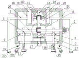
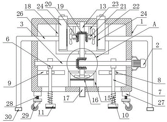
Fig. 1 is a schematic view of the overall structure provided by the present invention;
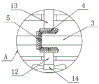
FIG. 2 is an enlarged view of section A of FIG. 1 according to the present invention;
FIG. 3 is a perspective view of the bearing seat of the present invention;
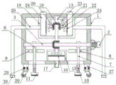
fig. 4 is a schematic view of the overall structure of embodiment 2 of the present invention;
in the figure: the cleaning device comprises a box body 1, a motor 2, a reciprocating screw rod 3, a first bevel gear 4, a second bevel gear 5, a bearing seat 6, a connecting rod 7, a gear 8, a toothed plate 9, a telescopic rod 10, a cleaning brush 11, a first rotating shaft 12, a second rotating shaft 13, a first fan blade 14, a cleaning box 15, a first filter screen 16, an input pipe 17, a cleaning box 18, a third bevel gear 19, a fourth bevel gear 20, a third rotating shaft 21, a second fan blade 22, a connecting plate 23, a drawer 24, a second filter screen 25, a pipe body 26, a supporting plate 27, a spring 28, a universal wheel 29 and a dust hood 30.
Detailed Description
The preferred embodiments of the present invention will be described in conjunction with the accompanying drawings, and it will be understood that they are presented herein only to illustrate and explain the present invention, and not to limit the present invention.
Example 1
Referring to the attached drawings 1-3, the utility model provides a novel environmental sanitation inspection vehicle, which comprises a box body 1, wherein a cleaning mechanism is arranged inside the box body 1;
the cleaning mechanism comprises a motor 2, the motor 2 is fixedly connected to one side of a box body 1, the motor 2 is fixedly connected with a reciprocating screw rod 3 through an output shaft, a first bevel gear 4 is fixedly sleeved inside the reciprocating screw rod 3, second bevel gears 5 are arranged at the top and the bottom of the first bevel gear 4, the first bevel gear 4 is meshed with two second bevel gears 5, bearing seats 6 are sleeved outside the reciprocating screw rod 3, connecting rods 7 are fixedly connected to the bottoms of the two bearing seats 6, gears 8 are fixedly sleeved outside the two connecting rods 7, toothed plates 9 are arranged on the rear sides of the two gears 8, the gears 8 are meshed with the toothed plates 9, the outer ends of the toothed plates 9 are fixedly connected to the inner walls on the two sides of the box body 1, two sliding grooves are formed in the bottom of the box body 1, the bottoms of the two connecting rods 7 penetrate through the sliding grooves, and telescopic rods 10 are fixedly connected to the bottoms of the two connecting rods 7, the bottom ends of the two telescopic rods 10 are fixedly connected with cleaning brushes 11, the bottoms and the tops of the two second bevel gears 5 are fixedly connected with a first rotating shaft 12 and a second rotating shaft 13, the bottom end of the first rotating shaft 12 is fixedly connected with a first fan blade 14, the inner wall of the bottom of the box body 1 is fixedly connected with a cleaning box 15, two sides of the cleaning box 15 are fixedly embedded with first filter screens 16, the bottom of the cleaning box 15 is fixedly connected with an input pipe 17, the inner wall of the top of the box body 1 is fixedly connected with a cleaning box 18, the inside of the second rotating shaft 13 is fixedly connected with a third bevel gear 19, two sides of the third bevel gear 19 are respectively provided with a fourth bevel gear 20, the third bevel gear 19 is meshed with the fourth bevel gear 20, the outer sides of the two fourth bevel gears 20 are respectively fixedly connected with a third rotating shaft 21, and the outer ends of the two third rotating shafts 21 are respectively fixedly connected with second fan blades 22, clean 18 tops of box and all fixedly inlay even board 23, clean 18 both sides of box and all inlay and be equipped with two drawers 24, two drawer 24 inboard all fixedly inlays and is equipped with second filter screen 25, two clean 18 tops of box and all extend to the box 1 outside, clean the equal fixedly connected with body 26 in 18 both sides of box, two the body 26 outer end runs through box 1 respectively and extends to the box 1 outside, body 26 bottom fixedly connected with suction hood 30, 1 bottom of the box is equipped with four supporting component.
Furthermore, one end of the reciprocating screw rod 3 extends into the other side of the box body 1, and the reciprocating screw rod 3 is connected with the box body 1 through a bearing;
further, the top ends of the second rotating shafts 13 extend to the inside of the cleaning box 18 and the box body 1, and the second rotating shafts 13 are connected with the box body 1 and the cleaning box 18 through bearings;
further, the bottom end of the first rotating shaft 12 extends to the inside of the cleaning box 15, and the first rotating shaft 12 is connected with the cleaning box 15 through a bearing;
furthermore, the two connecting plates 23 are fixedly sleeved outside the third rotating shaft 21, and the third rotating shaft 21 is connected with the connecting plates 23 through bearings;
further, the supporting component comprises supporting plates 27 and springs 28, the bottom ends of the four supporting plates 27 are fixedly connected to the tops of the springs 28, and the bottom ends of the four springs 28 are fixedly connected with universal wheels 29.
The utility model discloses a use as follows: when the utility model is used, the motor 2 drives the reciprocating screw rod 3 to rotate, the reciprocating screw rod 3 drives the bearing seat 6 to move, the bearing seat 6 drives the connecting rod 7 to move, the connecting rod 7 drives the gear to rotate, the gear rotates in the toothed plate 9, the connecting rod 7 drives the telescopic rod 10 to move left and right, the telescopic rod 10 drives the cleaning brush 11 to move left and right, the reciprocating screw rod 3 drives the first bevel gear 4 to rotate, the first bevel gear 4 drives the second bevel gear 5 to rotate, the second bevel gear 5 drives the first rotating shaft 12 to rotate, the first rotating shaft 12 drives the first fan blade 14 to rotate, the bottom of the box body 1 is provided with the cleaning box 15, the cleaning box 15 is internally provided with the first filter screen 16, the bottom of the cleaning box 15 is provided with the input pipe 17, thereby dust is sucked into the cleaning box 15, the second bevel gear 5 drives the second rotating shaft 13 to rotate, the second rotating shaft 13 drives the third bevel gear 19 to rotate, the third bevel gear 19 drives the fourth bevel gear 20 to rotate, fourth bevel gear 20 drives third pivot 21 and rotates, third pivot 21 drives second flabellum 22 and rotates, can drive connecting rod 7 through gear and bearing frame 6 and rotate and can remove about again, thereby it can rotate and can remove to drive the cleaning brush 11 on the telescopic link 10, thereby make the dust of cleaning inhale input tube 17 and body 26 the inside through first flabellum 14 and second flabellum 22, thereby inhale the dust and collect in cleaning box 15 and cleaning box 18 the inside through input tube 17 and body 26, thereby clean the dust of box 18 the inside and let drawer 24 drive the outside, the efficiency that the road surface was cleaned has been improved, the time of cleaning has been reduced, the artificial cost has been reduced, bring convenience for the scavenging personnel.
Example 2
Referring to fig. 4, the utility model provides a pair of novel sanitation inspection vehicle, it is different with embodiment 1, the supporting component includes backup pad 27 and spring 28, four the equal fixed connection in backup pad 27 bottom is at spring 28 top, four the equal fixedly connected with universal wheel 29 in spring 28 bottom, spring 28 quantity sets up to two, two spring 28 is symmetry form evenly distributed.
The utility model discloses a use as follows: the supporting component can better support the box body 1, and can also play a role of buffering through the spring 28 and the universal wheel 29, so that the universal wheel 29 can better rotate, the motor 2 drives the reciprocating screw rod 3 to rotate, the reciprocating screw rod 3 drives the bearing seat 6 to move, the bearing seat 6 drives the connecting rod 7 to move, the connecting rod 7 drives the gear to rotate, the gear rotates in the toothed plate 9, the connecting rod 7 drives the telescopic rod 10 to move left and right, the telescopic rod 10 drives the cleaning brush 11 to move left and right, the reciprocating screw rod 3 drives the first bevel gear 4 to rotate, the first bevel gear 4 drives the second bevel gear 5 to rotate, the second bevel gear 5 drives the first rotating shaft 12 to rotate, the first rotating shaft 12 drives the first fan blade 14 to rotate, the bottom of the box body 1 is provided with the cleaning box 15, the first filter screen 16 is arranged inside the cleaning box 15, the bottom of the cleaning box 15 is provided with the input pipe 17, so that dust is sucked into the cleaning box 15, and the second bevel gear 5 drives the second rotating shaft 13 to rotate, the second rotating shaft 13 drives the third bevel gear 19 to rotate.
The above description is only a preferred embodiment of the present invention, and any person skilled in the art may modify the present invention or modify it into an equivalent technical solution by using the technical solutions described above. Therefore, any simple modifications or equivalent replacements made according to the technical solution of the present invention belong to the scope of the claimed invention as far as possible.