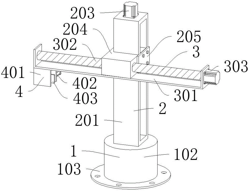
Workpiece clamping manipulator for automatic ultrasonic welding
Technical Field
The utility model belongs to automatic ultrasonic welding field especially relates to a manipulator is got to work piece clamp that automatic ultrasonic welding used.
Background
The principle of the automatic ultrasonic welding is that high-frequency vibration waves are transmitted to two objects needing to be welded into a whole, namely the surfaces of the objects, so that the two objects needing to be welded are combined together. Taking thermoplastic plastic welding as an example, when ultrasonic wave acts on a thermoplastic plastic contact surface, high-frequency vibration of tens of thousands or even tens of thousands of times per second can be generated, the high-frequency vibration reaching a certain amplitude transmits ultrasonic energy to a welding area through a weldment, and the welding area, namely the sound resistance of the interface of two welding areas is large, so that local high temperature can be generated, and the high temperature cannot be diffused in time due to poor thermal conductivity of the plastic, so that the high temperature is gathered on the welding area, the contact surfaces of the two plastics are rapidly melted, and the two plastics are fused into a whole after a certain pressure is applied.
However, in the prior art, the automatic ultrasonic welding workpiece taking and placing is generally completed by adopting a conveying belt and a pushing cylinder, which causes that: 1. the multi-dimensional moving and rotating device is not arranged, the clamping and releasing requirements of workpieces in different positions and shapes cannot be guaranteed, and the workpieces cannot be conveniently arranged in a production line; 2. the motor drive is not arranged, so that the programming control is not convenient, and the control convenience is reduced; 3. and due to no screw rod transmission, the micro movement cannot be realized, and the accurate control on the position cannot be ensured.
SUMMERY OF THE UTILITY MODEL
An object of the utility model is to provide a manipulator is got to work piece clamp of automatic ultrasonic bonding usefulness to solve the problem that proposes among the above-mentioned background art.
In order to achieve the above object, the utility model provides a following technical scheme:
a workpiece clamping manipulator for automatic ultrasonic welding comprises a base device for supporting, wherein a lifting device for moving up and down is mounted on the base device, a translation device for moving horizontally is mounted on the lifting device, and a clamping device for clamping and releasing a workpiece is mounted below the translation device; the base device comprises a base box, a connecting plate is arranged at the bottom of the base box, a motor bin is arranged in the base box, a servo motor is installed in the base box, and a transmission shaft is arranged on the servo motor; the translation device comprises a first support, a first lead screw is arranged in the middle of the first support, a first motor is arranged at one end of the first support, the first support is connected with the lifting device in a sliding mode, and the first lead screw is connected with the lifting device in a threaded mode; the clamping device comprises a fixing frame, two telescopic cylinders are symmetrically arranged behind the fixing frame, a movable plate is arranged in front of each telescopic cylinder, and anti-skid grains are arranged on the surface of each movable plate.
Further: the lifting device comprises a second support, a second lead screw is installed in the middle of the second support, a second motor is installed at the top of the second support, a first sliding block is installed on the second lead screw, and a cover plate is installed on one side of the first sliding block.
The second support supports the second motor to drive the second lead screw to rotate, and the second lead screw pushes the first sliding block to lift along the second support.
Further: the lifting device comprises a third support, a third lead screw is installed in the middle of the third support, a third motor is installed at the top of the third support, a sliding rod is arranged on one side of the third lead screw, and a second sliding block is installed on the third lead screw.
The third support supports the third motor to drive the third lead screw to rotate, and the third lead screw pushes the second sliding block to lift along the sliding rod.
Further: the base box and the connecting plate are both circular in shape, and the connecting plate and the base box are integrally formed.
The circular shape guarantees the uniformity of supporting stress, and the integrated forming guarantees the stability and reliability of the base device.
Further: the servo motor is connected with the base box through bolts, the first motor is connected with the first support through bolts, the fixed frame is connected with the first support through bolts, and the telescopic cylinder is connected with the movable plate and the fixed frame through bolts respectively.
Bolted connection is convenient for dismouting maintenance servo motor first motor the mount with telescopic cylinder.
Further: the first sliding block is in threaded connection with the second lead screw, the second motor is in bolted connection with the second support, and the first sliding block is in sliding connection with the second support.
Threaded connection guarantees that the second lead screw pushes the first sliding block, bolt connection is convenient for disassembly and assembly and maintenance the second motor, and sliding connection guarantees that the first sliding block is along the second support goes up and down.
Further: the second sliding block is in threaded connection with the third lead screw, the third motor is in bolted connection with the third support, and the second sliding block is in sliding connection with the sliding rod.
Threaded connection guarantees that the third lead screw pushes the second sliding block, bolt connection is convenient for disassembly, assembly and maintenance the third motor, and sliding connection guarantees that the second sliding block is lifted along the sliding rod.
The utility model discloses a theory of operation and use flow: the base box supports the servo motor, the servo motor drives the lifting device to rotate through the transmission shaft, the second support supports the second motor, the second lead screw is driven to rotate, the second lead screw pushes the first slider to lift along the second support, or the third support supports the third motor, the third lead screw is driven to rotate, the third lead screw pushes the second slider to lift along the sliding rod, the first support supports the first motor, the first lead screw is driven to rotate, the first support is driven to move along the first slider or the second slider horizontally stretches and moves, and the fixing frame supports the telescopic cylinder pushes the movable plate clamp to move to clamp a release workpiece.
Compared with the prior art, the beneficial effects of the utility model are that:
1. through the arrangement of multi-dimensional movement and rotation, the clamping and releasing requirements of workpieces in different positions and shapes are met, and the workpieces are convenient to arrange in a production line;
2. through the arrangement of motor drive, programming control is facilitated, and the convenience of control is improved;
3. through the arrangement of the screw rod transmission, the realization of small movement is facilitated, and the accurate control of the position is ensured.
Drawings
In order to more clearly illustrate the embodiments of the present invention or the technical solutions in the prior art, the drawings needed to be used in the description of the embodiments or the prior art will be briefly described below, it is obvious that the drawings in the following description are only some embodiments of the present invention, and for those skilled in the art, other drawings can be obtained according to these drawings without inventive exercise.
Fig. 1 is a schematic structural view of a workpiece clamping manipulator for automatic ultrasonic welding according to the present invention;
fig. 2 is a cross-sectional view of a base device of a workpiece clamping manipulator for automatic ultrasonic welding according to the present invention;
fig. 3 is a schematic view of a translation device of a workpiece clamping manipulator for automatic ultrasonic welding according to the present invention;
fig. 4 is a schematic view of a clamping device of a workpiece clamping manipulator for automatic ultrasonic welding according to the present invention;
fig. 5 is a schematic view of a lifting device of the workpiece clamping manipulator for automatic ultrasonic welding according to embodiment 1 of the present invention;
fig. 6 is a schematic view of a lifting device of embodiment 2 of a workpiece clamping manipulator for automatic ultrasonic welding.
In the reference symbols: 1. a base unit; 101. a base box; 102. a motor compartment; 103. a connecting plate; 104. a servo motor; 105. a drive shaft; 2. a lifting device; 201. a second bracket; 202. a second lead screw; 203. a second motor; 204. a first slider; 205. a cover plate; 206. a third support; 207. a third lead screw; 208. a third motor; 209. a second slider; 210. a slide bar; 3. a translation device; 301. a first bracket; 302. a first lead screw; 303. a first motor; 4. a clamping device; 401. a fixed mount; 402. a telescopic cylinder; 403. a movable plate; 404. and (4) anti-skid lines.
Detailed Description
In the description of the present invention, it is to be understood that the terms "center", "longitudinal", "lateral", "up", "down", "front", "back", "left", "right", "vertical", "horizontal", "top", "bottom", "inner", "outer", and the like, indicate orientations or positional relationships based on the orientations or positional relationships shown in the drawings, and are used merely for convenience of description and for simplicity of description, and do not indicate or imply that the device or element being referred to must have a particular orientation, be constructed and operated in a particular orientation, and therefore, should not be construed as limiting the present invention. Furthermore, the terms "first", "second", etc. are used for descriptive purposes only and are not to be construed as indicating or implying relative importance or implicitly indicating the number of technical features indicated. Thus, a feature defined as "first," "second," etc. may explicitly or implicitly include one or more of that feature. In the description of the present invention, "a plurality" means two or more unless otherwise specified.
In the description of the present invention, it is to be noted that, unless otherwise explicitly specified or limited, the terms "mounted," "connected," and "connected" are to be construed broadly, and may be, for example, fixedly connected, detachably connected, or integrally connected; can be mechanically or electrically connected; they may be connected directly or indirectly through intervening media, or they may be interconnected between two elements. The specific meaning of the above terms in the present invention can be understood by those of ordinary skill in the art through specific situations.
The present invention will be further explained with reference to the accompanying drawings:
example 1
As shown in fig. 1-5, a workpiece clamping manipulator for automatic ultrasonic welding comprises a base device 1 for supporting, a lifting device 2 for moving up and down is mounted on the base device 1, a translation device 3 for moving horizontally is mounted on the lifting device 2, and a clamping device 4 for clamping and releasing a workpiece is mounted below the translation device 3; the base device 1 comprises a base box 101, a connecting plate 103 is arranged at the bottom of the base box 101, a motor bin 102 is arranged in the base box 101, a servo motor 104 is arranged in the base box 101, and a transmission shaft 105 is arranged on the servo motor 104; the translation device 3 comprises a first bracket 301, a first lead screw 302 is arranged in the middle of the first bracket 301, a first motor 303 is arranged at one end of the first bracket 301, the first bracket 301 is connected with the lifting device 2 in a sliding manner, and the first lead screw 302 is connected with the lifting device 2 in a threaded manner; the clamping device 4 comprises a fixed frame 401, two telescopic cylinders 402 are symmetrically mounted behind the fixed frame 401, a movable plate 403 is mounted in front of the telescopic cylinders 402, and anti-skid patterns 404 are arranged on the surface of the movable plate 403.
Further: the lifting device 2 comprises a second support 201, a second lead screw 202 is installed in the middle of the second support 201, a second motor 203 is installed at the top of the second support 201, a first sliding block 204 is installed on the second lead screw 202, a cover plate 205 is installed on one side of the first sliding block 204, the second support 201 supports the second motor 203 to drive the second lead screw 202 to rotate, and the second lead screw 202 pushes the first sliding block 204 to lift along the second support 201; the base box 101 and the connecting plate 103 are both circular, and the connecting plate 103 and the base box 101 are integrally formed, so that the circular shape ensures the uniformity of supporting stress, and the integral forming ensures the stability and reliability of the base device 1; the servo motor 104 is connected with the base box 101 through bolts, the first motor 303 is connected with the first support 301 through bolts, the fixed frame 401 is connected with the first support 301 through bolts, and the telescopic cylinder 402 is respectively connected with the movable plate 403 and the fixed frame 401 through bolts, so that the servo motor 104, the first motor 303, the fixed frame 401 and the telescopic cylinder 402 can be conveniently disassembled, assembled and maintained through the bolts; the first sliding block 204 is in threaded connection with the second lead screw 202, the second motor 203 is in bolted connection with the second support 201, the first sliding block 204 is in sliding connection with the second support 201, the second lead screw 202 is guaranteed to push the first sliding block 204 through threaded connection, the second motor 203 is convenient to disassemble, assemble and maintain through bolted connection, and the first sliding block 204 is guaranteed to ascend and descend along the second support 201 through sliding connection.
Example 2
As shown in fig. 6, embodiment 2 differs from embodiment 1 in that: the lifting device 2 comprises a third bracket 206, a third lead screw 207 is installed in the middle of the third bracket 206, a third motor 208 is installed at the top of the third bracket 206, a sliding rod 210 is arranged on one side of the third lead screw 207, a second sliding block 209 is installed on the third lead screw 207, the third bracket 206 supports the third motor 208 to drive the third lead screw 207 to rotate, and the third lead screw 207 pushes the second sliding block 209 to lift along the sliding rod 210; the second sliding block 209 is in threaded connection with the third lead screw 207, the third motor 208 is in bolted connection with the third support 206, the second sliding block 209 is in sliding connection with the sliding rod 210, the threaded connection ensures that the third lead screw 207 pushes the second sliding block 209, the bolted connection is convenient for dismounting and maintaining the third motor 208, and the sliding connection ensures that the second sliding block 209 ascends and descends along the sliding rod 210.
The utility model discloses a theory of operation and use flow: the base box 101 supports the servo motor 104 to drive the lifting device 2 to rotate through the transmission shaft 105, the second bracket 201 supports the second motor 203 to drive the second lead screw 202 to rotate, the second lead screw 202 pushes the first slider 204 to lift along the second bracket 201, or the third bracket 206 supports the third motor 208 to drive the third lead screw 207 to rotate, the third lead screw 207 pushes the second slider 209 to lift along the slide bar 210, the first bracket 301 supports the first motor 303 to drive the first lead screw 302 to rotate, the first bracket 301 is driven to horizontally extend and retract along the first slider 204 or the second slider 209, and the fixed bracket 401 supports the telescopic cylinder 402 to push the movable plate 403 to move to clamp and release the workpiece.
The foregoing illustrates and describes the principles, general features, and advantages of the present invention. It will be understood by those skilled in the art that the present invention is not limited to the above embodiments, and that the foregoing embodiments and descriptions are provided only to illustrate the principles of the present invention without departing from the spirit and scope of the present invention.