CN214641778U - Based on numerical control longmen is multiaxis aggregate unit for machining center - Google Patents

Based on numerical control longmen is multiaxis aggregate unit for machining center Download PDF

Info

Publication number
CN214641778U
CN214641778U CN202120476553.XU CN202120476553U CN214641778U CN 214641778 U CN214641778 U CN 214641778U CN 202120476553 U CN202120476553 U CN 202120476553U CN 214641778 U CN214641778 U CN 214641778U
Authority
CN
China
Prior art keywords
electric
plate
machining center
axis linkage
base
Prior art date
Legal status (The legal status is an assumption and is not a legal conclusion. Google has not performed a legal analysis and makes no representation as to the accuracy of the status listed.)
Expired - Fee Related
Application number
CN202120476553.XU
Other languages
Chinese (zh)
Inventor
叶国华
Current Assignee (The listed assignees may be inaccurate. Google has not performed a legal analysis and makes no representation or warranty as to the accuracy of the list.)
Shenyang Tianhe Liyuan Aviation Manufacturing Co ltd
Original Assignee
Shenyang Tianhe Liyuan Aviation Manufacturing Co ltd
Priority date (The priority date is an assumption and is not a legal conclusion. Google has not performed a legal analysis and makes no representation as to the accuracy of the date listed.)
Filing date
Publication date
Application filed by Shenyang Tianhe Liyuan Aviation Manufacturing Co ltd filed Critical Shenyang Tianhe Liyuan Aviation Manufacturing Co ltd
Priority to CN202120476553.XU priority Critical patent/CN214641778U/en
Application granted granted Critical
Publication of CN214641778U publication Critical patent/CN214641778U/en
Expired - Fee Related legal-status Critical Current
Anticipated expiration legal-status Critical

Links

Images

Landscapes

  • Jigs For Machine Tools (AREA)

Abstract

本实用新型公开了一种基于数控龙门加工中心用多轴联动装置,包括底座、刀具和放置板,底座的顶部中部固定安装有工作台,底座的顶部一侧活动连接有多轴联动机构,放置板的顶部活动连接有夹块,工作台的前部可拆卸安装有控制面板,工作台的顶部活动连接有放置机构,底座的顶部活动连接有更换机构,放置机构包括支撑杆。上述方案中,第一电动滑轨设置为跑道形,可以在一个工件加工完成后,通过第一电动滑块的滑动使加工完成的工件移动到第一电动滑轨的另一侧,再通过另外的第一电动滑块将未加工的工件移动到刀具的下方,此时不需要停止装置就可以通过人工装卸工件,从而使装置可以持续进行工作,提高了工作效率。

Figure 202120476553

The utility model discloses a multi-axis linkage device based on a numerically controlled gantry machining center, which comprises a base, a cutter and a placing plate. A worktable is fixedly installed in the middle of the top of the base, and a multi-axis linkage mechanism is movably connected to one side of the top of the base. The top of the board is movably connected with a clamping block, the front of the workbench is detachably installed with a control panel, the top of the workbench is movably connected with a placement mechanism, the top of the base is movably connected with a replacement mechanism, and the placement mechanism includes a support rod. In the above solution, the first electric slide rail is set in the shape of a racetrack. After a workpiece is processed, the processed workpiece can be moved to the other side of the first electric slide rail through the sliding of the first electric slide rail, and then through the other side of the electric slide rail. The first electric sliding block moves the unprocessed workpiece to the bottom of the tool, and the workpiece can be manually loaded and unloaded without stopping the device at this time, so that the device can continue to work and improve the work efficiency.

Figure 202120476553

Description

Based on numerical control longmen is multiaxis aggregate unit for machining center
Technical Field
The utility model relates to a numerical control technology field, more specifically say, the utility model relates to a based on numerical control is multiaxis aggregate unit for longmen machining center.
Background
With the development of numerical control technology, the functions of a numerical control gantry machining center are more and more, the existing numerical control gantry machining center is provided with a multi-axis linkage device, the existing multi-axis linkage device is used for machining a workpiece by driving a cutter to move on a plurality of coordinate axes, and the workpiece machined by adopting the method has good surface quality and size consistency and can meet the requirements; the conventional multi-shaft linkage device only can process workpieces one by one when processing the workpieces, the device is required to be stopped after the processing is finished, and then the workpieces are assembled and disassembled manually, so that the mode consumes more time and the working efficiency is lower; when different workpieces need to be machined by the conventional multi-shaft linkage device, the device needs to be stopped manually and clamping blocks for fixing the workpieces need to be replaced, so that more time is consumed, and the working efficiency is lower.
SUMMERY OF THE UTILITY MODEL
In order to overcome the above-mentioned defect of prior art, the embodiment of the utility model provides a multiaxis aggregate unit for gantry machining center based on numerical control to solve current multiaxis aggregate unit and adopt artifical loading and unloading work piece to lead to the problem that work efficiency is lower and current multiaxis aggregate unit needs artifical change clamp splice.
In order to solve the technical problem, the utility model provides a following technical scheme: a multi-axis linkage device for a numerical control gantry-based machining center comprises a base, a cutter and a placing plate, wherein a workbench is fixedly installed in the middle of the top of the base, a multi-axis linkage mechanism is movably connected to one side of the top of the base, a clamping block is movably connected to the top of the placing plate, a control panel is detachably installed on the front portion of the workbench, a placing mechanism is movably connected to the top of the workbench, and a replacing mechanism is movably connected to the top of the base;
the placing mechanism comprises a supporting rod, a first electric slide rail is fixedly connected to the top of the supporting rod, a first electric slide block is slidably connected to the top of the first electric slide rail, a supporting plate is fixedly connected to the top of the first electric slide block, a clamping block is fixedly mounted on the top of the supporting plate, and a clamping groove is formed in the bottom of the placing plate;
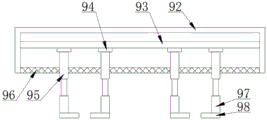
the change mechanism includes the support column, one side top fixedly connected with roof of support column, the electronic slide rail of inside fixedly connected with second of roof, the bottom sliding connection of the electronic slide rail of second has the electronic slider of second, the bottom movable mounting of the electronic slider of second has electric telescopic handle, logical groove has been seted up to the bottom of roof, electric telescopic handle's bottom fixedly connected with riser, the bottom fixedly connected with diaphragm of riser.
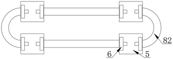
The shape of the first electric slide rail is a runway shape, the top end of the supporting rod is connected with two sides of the bottom of the runway-shaped first electric slide rail, and the bottom end of the supporting rod is connected with two sides of the top of the workbench.
The clamping block is clamped with the clamping groove, and the top of the supporting plate is movably connected with the bottom of the placing plate.
The input ends of the first electric sliding rail, the first electric sliding block, the second electric sliding rail, the second electric sliding block and the electric telescopic rod are electrically connected with the output end of the control panel.
The bottom end of the supporting column is connected with the other side of the top of the base, the supporting column is located on one side of the workbench, and the top plate is located at the top of the first electric sliding rail.
The through groove penetrates through the bottom of the top plate, and the electric telescopic rod extends out of the top plate through the through groove.
Wherein, the quantity of second electric slider is a plurality of, the quantity phase-match of the quantity of electric telescopic handle, riser and diaphragm and the quantity of second electric slider just is a plurality of, and per two electric telescopic handle, riser and diaphragm are a set of, the length of diaphragm is greater than the length of riser, in every group the direction of diaphragm is relative.
The utility model discloses an above-mentioned technical scheme's beneficial effect as follows:
in the scheme, the first electric slide rail is in a runway shape, after one workpiece is machined, the machined workpiece can be moved to the other side of the first electric slide rail through the sliding of the first electric slide block, and then the unmachined workpiece is moved to the lower part of the cutter through the other first electric slide block; in the scheme, the second electric sliding block can slide on the second electric sliding rail, so that the electric telescopic rod is driven, the vertical plate and the transverse plate move, the electric telescopic rod stretches out and draws back, one end of the transverse plate is moved to the bottom of the placed plate, the placed plate can be taken out through stretching of the electric telescopic rod and sliding of the second electric sliding block, the placed plate and the clamping blocks on the placed plate can be replaced through the other second electric sliding block and the electric telescopic rod, manual replacement is avoided, and the working efficiency is improved.
Drawings
Fig. 1 is a schematic view of the overall structure of the present invention;
fig. 2 is an enlarged schematic structural view of fig. 1 a according to the present invention;
fig. 3 is a schematic structural view of a first electric slide rail of the present invention;
fig. 4 is a schematic view of the top plate structure of the present invention;
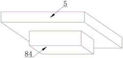
fig. 5 is a schematic view of the supporting plate structure of the present invention.
[ reference numerals ]
1. A base; 2. a work table; 3. a multi-axis linkage mechanism; 4. a cutter; 5. placing the plate; 6. a clamping block; 7. a control panel; 8. a placement mechanism; 81. a support bar; 82. a first electric slide rail; 83. a first electric slider; 84. a support plate; 85. a clamping block; 86. a card slot; 9. a mechanism is replaced; 91. a support pillar; 92. a top plate; 93. a second electric slide rail; 94. a second electric slider; 95. an electric telescopic rod; 96. a through groove; 97. a vertical plate; 98. a transverse plate.
Detailed Description
In order to make the technical problems, technical solutions and advantages to be solved by the present invention clearer, the following detailed description will be given with reference to the accompanying drawings and specific embodiments.
The embodiment of the utility model provides a multiaxis aggregate unit for machining center based on numerical control longmen as attached fig. 1 to fig. 5, including base 1, cutter 4 and placing plate 5, the top middle part of base 1 is fixedly provided with workstation 2, one side of the top of base 1 is movably connected with multiaxis aggregate unit 3, the top of placing plate 5 is movably connected with clamp splice 6, the front part of workstation 2 is detachably provided with control panel 7, the top of workstation 2 is movably connected with placing mechanism 8, the top of base 1 is movably connected with change mechanism 9;
the placing mechanism 8 comprises a supporting rod 81, a first electric slide rail 82 is fixedly connected to the top of the supporting rod 81, a first electric slide block 83 is slidably connected to the top of the first electric slide rail 82, a supporting plate 84 is fixedly connected to the top of the first electric slide block 83, a clamping block 85 is fixedly installed on the top of the supporting plate 84, and a clamping groove 86 is formed in the bottom of the placing plate 5;
change mechanism 9 and include support column 91, one side top fixedly connected with roof 92 of support column 91, the inside fixedly connected with second electric slide rail 93 of roof 92, the bottom sliding connection of second electric slide rail 93 has second electric slider 94, the bottom movable mounting of second electric slider 94 has electric telescopic handle 95, logical groove 96 has been seted up to the bottom of roof 92, electric telescopic handle 95's bottom fixedly connected with riser 97, the bottom fixedly connected with diaphragm 98 of riser 97.
The shape of the first electric slide rail 82 is set to be runway-shaped, the top end of the support rod 81 is connected with the two sides of the bottom of the runway-shaped first electric slide rail 82, and the bottom end of the support rod 81 is connected with the two sides of the top of the workbench 2.
The clamping block 85 is clamped with the clamping groove 86, and the top of the supporting plate 84 is movably connected with the bottom of the placing plate 5.
The input ends of the first electric slide rail 82, the first electric slide block 83, the second electric slide rail 93, the second electric slide block 94 and the electric telescopic rod 95 are electrically connected with the output end of the control panel 7.
The bottom of support column 91 is connected with the top opposite side of base 1, support column 91 is located one side of workstation 2, roof 92 is located the top of first electronic slide rail 82.
The through groove 96 penetrates the bottom of the top plate 92, and the electric telescopic rod 95 extends out of the top plate 92 through the through groove 96.
The quantity of second electric slider 94 is a plurality of, the quantity phase-match of electric telescopic handle 95, riser 97 and diaphragm 98 and the quantity of second electric slider 94 just is a plurality of, and per two electric telescopic handle 95, riser 97 and diaphragm 98 are a set of, the length of diaphragm 98 is greater than the length of riser 97, in every group the direction of diaphragm 98 is relative.
Wherein, the brand of control panel 7 is delaxi electricity, and its model is KG316T220XK, and the brand of first electronic slide rail 82, first electronic slider 83, second electronic slide rail 93 and second electronic slider 94 is VOBOSH, and its model is VSC80, and the brand of electric telescopic handle 95 is TOMUU, and its model is U7.
The working process of the utility model is as follows:
when the device works, a workpiece is placed at the top of the placing plate 5 and is fixed through the clamping block 6, then the first electric slide block 83 is controlled to slide on the first electric slide rail 82, so that the placing plate 5 and the workpiece are driven to move through the supporting plate 84, the clamping block 85 and the clamping groove 86, after the workpiece is machined, the machined workpiece is moved to the other side of the runway-shaped first electric slide rail 82 through the sliding of the first electric slide block 83, and the unmachined workpiece is moved to the lower part of the cutter 4 through the other first electric slide block 83; when the device needs to process different workpieces, the placing plate 5 is driven to move to the lower side of the top plate 92 through the first electric sliding block 83, then the two second electric sliding blocks 94 are controlled to slide on the second electric sliding rails 93, the electric telescopic rod 95 is driven, the vertical plate 97 and the transverse plate 98 move, the electric telescopic rod 95 stretches and retracts and the second electric sliding blocks 94 slide, one end of the transverse plate 98 moves to the bottom of the placing plate 5, the two sides of the placing plate 5 are clamped through the vertical plates 97, the placing plate 5 can be taken out of the clamping block 85 and moved to one side through stretching of the electric telescopic rod 95 and sliding of the second electric sliding blocks 94, the placing plate 5 and the clamping blocks 6 on the placing plate are replaced through the other second electric sliding blocks 94 and the electric telescopic rods 95, manual replacement is avoided, and the working efficiency is improved.
According to the scheme, the support rod 81, the first electric slide rail 82, the first electric slide block 83, the support plate 84, the fixture block 85 and the clamping groove 86 are matched, so that the situation that the device is stopped to assemble and disassemble workpieces is avoided, and the device can continuously work; support column 91, roof 92, electronic slide rail 93 of second, electronic slider 94 of second, electric telescopic handle 95, logical groove 96, riser 97 and diaphragm 98's cooperation has avoided the manual work to change and has placed board 5 and clamp splice 6, has guaranteed to change fast.
The points to be finally explained are: first, in the description of the present application, it should be noted that, unless otherwise specified and limited, the terms "mounted," "connected," and "connected" should be understood broadly, and may be a mechanical connection or an electrical connection, or a communication between two elements, and may be a direct connection, and "upper," "lower," "left," and "right" are only used to indicate a relative positional relationship, and when the absolute position of the object to be described is changed, the relative positional relationship may be changed;
secondly, the method comprises the following steps: in the drawings of the disclosed embodiments of the present invention, only the structures related to the disclosed embodiments are referred to, and other structures can refer to the common design, and under the condition of no conflict, the same embodiment and different embodiments of the present invention can be combined with each other;
and finally: the above description is only for the preferred embodiment of the present invention and should not be taken as limiting the invention, and any modifications, equivalent replacements, improvements, etc. made within the spirit and principle of the present invention should be included in the protection scope of the present invention.

Claims (7)

1.一种基于数控龙门加工中心用多轴联动装置,包括底座(1)、刀具(4)和放置板(5),所述底座(1)的顶部中部固定安装有工作台(2),所述底座(1)的顶部一侧活动连接有多轴联动机构(3),所述放置板(5)的顶部活动连接有夹块(6),所述工作台(2)的前部可拆卸安装有控制面板(7),其特征在于,所述工作台(2)的顶部活动连接有放置机构(8),所述底座(1)的顶部活动连接有更换机构(9);1. A multi-axis linkage device based on a CNC gantry machining center, comprising a base (1), a tool (4) and a placement plate (5), and a worktable (2) is fixedly installed in the top middle of the base (1), The top side of the base (1) is movably connected with a multi-axis linkage mechanism (3), the top of the placing plate (5) is movably connected with a clamping block (6), and the front part of the worktable (2) can be movably connected. A control panel (7) is disassembled and installed, characterized in that a placement mechanism (8) is movably connected to the top of the workbench (2), and a replacement mechanism (9) is movably connected to the top of the base (1); 所述放置机构(8)包括支撑杆(81),所述支撑杆(81)的顶部固定连接有第一电动滑轨(82),所述第一电动滑轨(82)的顶部滑动连接有第一电动滑块(83),所述第一电动滑块(83)的顶部固定连接有支撑板(84),所述支撑板(84)的顶部固定安装有卡块(85),所述放置板(5)的底部开设有卡槽(86);The placement mechanism (8) includes a support rod (81), the top of the support rod (81) is fixedly connected with a first electric sliding rail (82), and the top of the first electric sliding rail (82) is slidably connected with a A first electric slider (83), a support plate (84) is fixedly connected to the top of the first electric slider (83), a clamping block (85) is fixedly installed on the top of the support plate (84), and the The bottom of the placing plate (5) is provided with a card slot (86); 所述更换机构(9)包括支撑柱(91),所述支撑柱(91)的一侧顶部固定连接有顶板(92),所述顶板(92)的内部固定连接有第二电动滑轨(93),所述第二电动滑轨(93)的底部滑动连接有第二电动滑块(94),所述第二电动滑块(94)的底部活动安装有电动伸缩杆(95),所述顶板(92)的底部开设有通槽(96),所述电动伸缩杆(95)的底端固定连接有竖板(97),所述竖板(97)的底端固定连接有横板(98)。The replacement mechanism (9) includes a support column (91), a top plate (92) is fixedly connected to one side of the support column (91), and a second electric slide rail (92) is fixedly connected to the inside of the top plate (92). 93), a second electric sliding block (94) is slidably connected to the bottom of the second electric sliding rail (93), and an electric telescopic rod (95) is movably installed at the bottom of the second electric sliding block (94), so A through groove (96) is opened at the bottom of the top plate (92), a vertical plate (97) is fixedly connected to the bottom end of the electric telescopic rod (95), and a horizontal plate is fixedly connected to the bottom end of the vertical plate (97). (98). 2.根据权利要求1所述的基于数控龙门加工中心用多轴联动装置,其特征在于,所述第一电动滑轨(82)的形状设置为跑道形,所述支撑杆(81)的顶端与跑道形第一电动滑轨(82)的底部两侧连接,所述支撑杆(81)的底端与工作台(2)的顶部两侧连接。2 . The multi-axis linkage device based on CNC gantry machining center according to claim 1 , wherein the shape of the first electric slide rail ( 82 ) is set in a racetrack shape, and the top end of the support rod ( 81 ) is set in the shape of a racetrack. 3 . It is connected with both sides of the bottom of the racetrack-shaped first electric sliding rail (82), and the bottom end of the support rod (81) is connected with both sides of the top of the workbench (2). 3.根据权利要求1所述的基于数控龙门加工中心用多轴联动装置,其特征在于,所述卡块(85)与卡槽(86)卡接,所述支撑板(84)的顶部与放置板(5)的底部活动连接。3. The multi-axis linkage device based on CNC gantry machining center according to claim 1, wherein the clamping block (85) is clamped with the clamping groove (86), and the top of the support plate (84) is connected to the clamping groove (86). Place the bottom articulation of the plate (5). 4.根据权利要求1所述的基于数控龙门加工中心用多轴联动装置,其特征在于,所述第一电动滑轨(82)、第一电动滑块(83)、第二电动滑轨(93)、第二电动滑块(94)和电动伸缩杆(95)的输入端与控制面板(7)的输出端电性连接。4. The multi-axis linkage device based on CNC gantry machining center according to claim 1, characterized in that the first electric sliding rail (82), the first electric sliding block (83), the second electric sliding rail ( 93), the input end of the second electric sliding block (94) and the electric telescopic rod (95) are electrically connected with the output end of the control panel (7). 5.根据权利要求1所述的基于数控龙门加工中心用多轴联动装置,其特征在于,所述支撑柱(91)的底端与底座(1)的顶部另一侧连接,所述支撑柱(91)位于工作台(2)的一侧,所述顶板(92)位于第一电动滑轨(82)的顶部。5. The multi-axis linkage device based on CNC gantry machining center according to claim 1, wherein the bottom end of the support column (91) is connected with the other side of the top of the base (1), and the support column (91) is located on one side of the workbench (2), and the top plate (92) is located on the top of the first electric sliding rail (82). 6.根据权利要求1所述的基于数控龙门加工中心用多轴联动装置,其特征在于,所述通槽(96)贯通顶板(92)的底部,所述电动伸缩杆(95)通过通槽(96)伸出顶板(92)。6. The multi-axis linkage device based on CNC gantry machining center according to claim 1, characterized in that the through groove (96) penetrates through the bottom of the top plate (92), and the electric telescopic rod (95) passes through the through groove (96) extends out of the top plate (92). 7.根据权利要求1所述的基于数控龙门加工中心用多轴联动装置,其特征在于,所述第二电动滑块(94)的数量为若干个,所述电动伸缩杆(95)、竖板(97)和横板(98)的数量与第二电动滑块(94)的数量相匹配且均为若干个,并且每两个所述电动伸缩杆(95)、竖板(97)和横板(98)为一组,所述横板(98)的长度大于竖板(97)的长度,每组内所述横板(98)的方向相对。7. The multi-axis linkage device based on CNC gantry machining center according to claim 1, characterized in that, the number of the second electric sliders (94) is several, the electric telescopic rod (95), the vertical The number of the plate (97) and the horizontal plate (98) matches the number of the second electric sliders (94), and both are several, and every two electric telescopic rods (95), vertical plates (97) and The transverse plates (98) are a group, the length of the transverse plates (98) is greater than the length of the vertical plates (97), and the directions of the transverse plates (98) in each group are opposite.
CN202120476553.XU 2021-03-05 2021-03-05 Based on numerical control longmen is multiaxis aggregate unit for machining center Expired - Fee Related CN214641778U (en)

Priority Applications (1)

Application Number Priority Date Filing Date Title
CN202120476553.XU CN214641778U (en) 2021-03-05 2021-03-05 Based on numerical control longmen is multiaxis aggregate unit for machining center

Applications Claiming Priority (1)

Application Number Priority Date Filing Date Title
CN202120476553.XU CN214641778U (en) 2021-03-05 2021-03-05 Based on numerical control longmen is multiaxis aggregate unit for machining center

Publications (1)

Publication Number Publication Date
CN214641778U true CN214641778U (en) 2021-11-09

Family

ID=78451188

Family Applications (1)

Application Number Title Priority Date Filing Date
CN202120476553.XU Expired - Fee Related CN214641778U (en) 2021-03-05 2021-03-05 Based on numerical control longmen is multiaxis aggregate unit for machining center

Country Status (1)

Country Link
CN (1) CN214641778U (en)

Similar Documents

Publication Publication Date Title
CN103506721B (en) The wire-electrode cutting and processing method of annular workpiece and device
CN114406649B (en) Scissor assembly mechanism for keyboard keys
CN218487300U (en) Milling machine turnover mechanism for part processing
CN105328500A (en) Numerical control machine tool internally provided with automatic feeding and discharging mechanism and method for conducting workpiece feeding and discharging
CN106695292A (en) Efficient device for automatically loading and unloading needle for taking out card
CN218503910U (en) Adjustable multi-workpiece fixed tool clamp
CN209774920U (en) A Wood Positioning Mechanism for a Solid Wood Four-Axis Horizontal Machining Center
CN219336374U (en) Equipment for enabling sectional materials to be welded, combined and polished rapidly
CN218799838U (en) Welding device for assembling metal parts of numerical control machine tool
CN217803447U (en) Self-adhesion foam-rubber cushion pastes installation
CN214135068U (en) Gantry machining center
CN217966056U (en) A loading and unloading device for CNC lathe board processing
CN215469948U (en) High-automation numerical control machine tool
CN205498451U (en) An origin point self-positioning numerical control plate engraving machine
CN209503318U (en) A kind of robot welding fixture
CN205363273U (en) Numerical control machining center
CN209849953U (en) Five-sided milling machine of numerical control axle
CN210334698U (en) A CNC cutting device
CN116038470A (en) A multi-axis workstation for casting burrs
CN222493220U (en) Clamping device for machining of die milling machine
CN208050745U (en) Photovoltaic bracket shaping mould
CN209753241U (en) Side gluing device
CN218364037U (en) Automatic high-effect flat grinder of material loading
CN219336786U (en) Double-shaft type mobile platform for tapping machine
CN219402470U (en) Multi-shaft milling cutter

Legal Events

Date Code Title Description
GR01 Patent grant
GR01 Patent grant
CF01 Termination of patent right due to non-payment of annual fee

Granted publication date: 20211109

CF01 Termination of patent right due to non-payment of annual fee