CN214641751U - Gantry machining center - Google Patents
Gantry machining center Download PDFInfo
- Publication number
- CN214641751U CN214641751U CN202120514715.4U CN202120514715U CN214641751U CN 214641751 U CN214641751 U CN 214641751U CN 202120514715 U CN202120514715 U CN 202120514715U CN 214641751 U CN214641751 U CN 214641751U
- Authority
- CN
- China
- Prior art keywords
- main shaft
- saddle
- box
- lathe bed
- machining center
- Prior art date
- Legal status (The legal status is an assumption and is not a legal conclusion. Google has not performed a legal analysis and makes no representation as to the accuracy of the status listed.)
- Active
Links
Images
Abstract
The utility model discloses a gantry machining center, which comprises a lathe bed, a workbench and a spindle box, wherein the workbench is connected on the upper end surface of the lathe bed in a sliding way, stand columns are symmetrically arranged on two sides of the lathe bed, the upper ends of the two stand columns are connected with a cross beam together, a first roller linear guide rail and a first roller screw rod are arranged on the cross beam, the spindle box is arranged on the first roller linear guide rail through a saddle, and a spindle is arranged on the spindle box; the workpiece to be processed is arranged on the workbench and is driven by the workbench to move left and back and forth, the portal frame main body does not need to move, and the phenomena of deviation, unstable gravity center and the like generated in the moving process of the portal frame and a spindle box on the portal frame are avoided. The utility model discloses simple structure, it is practical convenient, the operation is stable, has improved machining efficiency, adds that the aircraft nose goes up and down more stably man-hour, reduces machining error, has alleviateed ball screw's drive power.
Description
Technical Field
The utility model belongs to the technical field of machining center, concretely relates to longmen machining center.
Background
Machining centers have evolved from numerically controlled milling machines. The numerical control milling machine is different from a numerical control milling machine in that the machining center has the capability of automatically exchanging machining tools, and the machining tools on the main shaft can be changed through the automatic tool changing device in one-time clamping by installing tools with different purposes on the tool magazine, so that multiple machining functions are realized.
The existing machining center is generally divided into a gantry machining center and a horizontal machining center, and the existing movable beam type gantry machining center has the defects of unreasonable moving connection structure and imperfect stress structure and support distribution design, so that the moving connection structure is easy to seriously stress on a fragile support part, and structural failure is caused to occur quickly after long-term application.
SUMMERY OF THE UTILITY MODEL
An object of the utility model is to provide a longmen machining center to solve the problem that proposes among the above-mentioned background art.
In order to achieve the above object, the utility model provides a following technical scheme: a gantry machining center comprises a lathe bed, a workbench and a spindle box, wherein the workbench is slidably connected to the upper end face of the lathe bed, stand columns are symmetrically arranged on two sides of the lathe bed, the upper ends of the two stand columns are connected with a cross beam together, a first roller linear guide rail and a first roller screw rod are arranged on the cross beam, the spindle box is arranged on the first roller linear guide rail through a saddle, and a spindle is arranged on the spindle box; the workpiece to be processed is arranged on the workbench and is driven by the workbench to move left and back and forth, the portal frame main body does not need to move, and the phenomena of deviation, unstable gravity center and the like generated in the moving process of the portal frame and a spindle box on the portal frame are avoided.
The utility model discloses a further improvement lies in: the headstock is square ram headstock, square ram headstock includes motor, gear box, saddle, main shaft box, second ball screw and main shaft, main shaft box and second ball screw dress are in the saddle be equipped with the gear box on the main shaft box be equipped with the motor on the gear box be equipped with shaft coupling and main shaft in the main shaft box, the output shaft of motor is connected with the input transmission of gear box, shaft coupling and main shaft transmission are passed through to the output of gear box, the motor drives the gear box drives the main shaft rotatory, second ball screw drives the main shaft box and slides from top to bottom in the saddle install the connecting plate on the saddle, through the upset of main shaft box is restricted to the connecting plate.
The utility model discloses a further improvement lies in: and a grating reading head is arranged on the saddle and used for reading the upper position and the lower position of the spindle box and feeding back to the motor.
The utility model discloses a further improvement lies in: the mounting precision is ensured by arranging the gibs among the saddle, the connecting plate and the main shaft box body, adjusting the gap through the gibs, and the two oil cylinders are symmetrically arranged at the top of the saddle and balance partial weight of part of the main shaft box body through the two oil cylinders, so that the driving force of the ball screw is reduced.
The utility model discloses a further improvement lies in: and a lubricating joint is arranged on the panel.
The utility model discloses a further improvement lies in: two groups of third roller linear guide rails are symmetrically arranged on the lathe bed, a third ball screw is arranged on the lathe bed between the two groups of third roller linear guide rails, and the third ball screw drives the workbench to move back and forth on the third roller linear guide rails.
The utility model discloses a technological effect and advantage:
the structure is simple, the operation is practical and convenient, the processing efficiency is improved, the lifting of the machine head is more stable during processing, and the processing error is reduced; the worktable drives the gantry to move left and back and forth, the gantry body does not need to move, and the phenomena of deviation, unstable gravity center and the like generated in the moving process of the gantry and a main spindle box on the gantry are avoided; the square ram spindle box is arranged on the sliding saddle, the upper weight and the lower weight of the square ram spindle box are balanced by the oil hydraulic cylinder, and the gear box is arranged at the top of the spindle box and used for controlling the speed change and gear shift of the spindle box; reading the upper and lower positions of the spindle box through a grating reading head, and feeding back to the motor; the gap is adjusted through the gib, the installation precision is guaranteed, and partial weight of a part of spindle box bodies is balanced at the top of the saddle through the two oil cylinders, so that the driving force of the ball screw is reduced.
Drawings
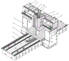
Fig. 1 is a schematic structural view of the present invention;
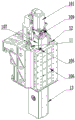
FIG. 2 is a schematic structural diagram of a spindle head;
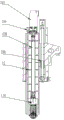
FIG. 3 is a cross-sectional view of the headstock;
in the figure: the device comprises a vertical column 1, a workbench 2, a third ball screw 3, a third roller linear guide 4, a lathe bed 5, a first roller linear guide 6, a cross beam 7, a first roller screw 8, a gear box 9, an oil cylinder 11, a saddle 12, a spindle box 13, a motor 101, a panel 105, a connecting plate 106, a spindle box 107, a coupler 108, a second ball screw 109 and a spindle 110.
Detailed Description
The technical solutions in the embodiments of the present invention will be described clearly and completely with reference to the accompanying drawings in the embodiments of the present invention, and it is obvious that the described embodiments are only some embodiments of the present invention, not all embodiments. Based on the embodiments in the present invention, all other embodiments obtained by a person skilled in the art without creative work belong to the protection scope of the present invention.
Fig. 1 to 3 show a specific embodiment of a gantry machining center: the numerical control lathe comprises a lathe bed 5, a workbench 2 and a spindle box 13, wherein the workbench 2 is slidably connected to the upper end surface of the lathe bed 5, two groups of third roller linear guide rails 4 are symmetrically arranged on the lathe bed 5, a third ball screw 3 is arranged on the lathe bed 5 between the two groups of third roller linear guide rails 4, and the third ball screw 3 drives the workbench 2 to move back and forth on the third roller linear guide rails 4; the two sides of the lathe bed 5 are symmetrically provided with upright posts 1, the upper ends of the two upright posts 1 are connected with a cross beam 7 together, the cross beam 7 is provided with a first roller linear guide rail 6 and a first roller screw rod 8, the main shaft box 13 is arranged on the first roller linear guide rail 6 through a saddle 12, the main shaft box 13 is provided with a main shaft 110, a workpiece to be processed is arranged on the workbench 2 and is driven by the workbench 2 to move left and back and forth, the main body of the portal frame does not need to move, and the phenomena of deviation, unstable gravity center and the like of the portal frame and the main shaft box on the portal frame in the moving process are avoided;
the spindle box 13 is a square ram spindle box, the square ram spindle box comprises a motor 101, a gear box 9, a saddle 12, a spindle box body 107, a second ball screw 109 and a spindle 110, the spindle box body 107 and the second ball screw 109 are arranged in the saddle 12, a gear box 9 is arranged on the main shaft box body 107, a motor 101 is arranged on the gear box 9, a coupling 108 and a main shaft 110 are arranged in the main shaft box 107, an output shaft of the motor 101 is in transmission connection with an input end of the gear box 9, the output end of the gear box 9 is in transmission with a main shaft 110 through a coupler 108, the motor 101 drives the gear box 9, the gear box 9 drives the main shaft 110 to rotate, the second ball screw 109 drives the main shaft box 13 to slide up and down in the saddle 12, a connecting plate 106 is arranged on the saddle 12, and the overturn of the spindle box 107 is limited by the connecting plate 106;
a grating reading head is arranged on the saddle 12, and the grating reading head reads the upper position and the lower position of the spindle box and feeds back the upper position and the lower position to the motor 101;
the mounting structure is characterized in that an insert 105 is arranged among the saddle 12, the connecting plate 106 and the main spindle box 107, a lubricating joint is arranged on the insert 105, the mounting precision is guaranteed by adjusting the gap through the insert 105, the two oil cylinders 11 are symmetrically arranged on the top of the saddle 12, and partial weight of part of the main spindle box is balanced through the two oil cylinders 11, so that the driving force of the ball screw is reduced.
The utility model has simple structure, practicality and convenience, stable operation, improved processing efficiency, more stable lifting of the machine head during processing and reduced processing error; the worktable drives the gantry to move left and back and forth, the gantry body does not need to move, and the phenomena of deviation, unstable gravity center and the like generated in the moving process of the gantry and a main spindle box on the gantry are avoided; the square ram spindle box is arranged on the sliding saddle, the upper weight and the lower weight of the square ram spindle box are balanced by the oil hydraulic cylinder, and the gear box is arranged at the top of the spindle box and used for controlling the speed change and gear shift of the spindle box; reading the upper and lower positions of the spindle box through a grating reading head, and feeding back to the motor; the gap is adjusted through the gib, the installation precision is guaranteed, and partial weight of a part of spindle box bodies is balanced at the top of the saddle through the two oil cylinders, so that the driving force of the ball screw is reduced.
The utility model discloses not limited to above-mentioned embodiment, all adopt and the utility model discloses similar structure and method realize the utility model discloses all modes of purpose all are within the protection scope of the utility model.
The applicant further states that the present invention is described by the above embodiments, but the present invention is not limited to the above embodiments, i.e. the present invention is not limited to the above embodiments, and the present invention can be implemented only by relying on the above methods and structures. It should be clear to those skilled in the art that any improvement of the present invention is to the present invention, and the addition of the equivalent replacement of the implementation method and the steps, the selection of the specific mode, etc. all fall within the protection scope and the disclosure scope of the present invention.
The utility model discloses not limited to above-mentioned embodiment, all adopt and the utility model discloses similar structure and method realize the utility model discloses all modes of purpose all are within the protection scope of the utility model.
Claims (6)
1. The utility model provides a longmen machining center, includes lathe bed (5), workstation (2) and headstock (13), its characterized in that: the upper end face of the lathe bed (5) is connected with a workbench (2) in a sliding mode, two sides of the lathe bed (5) are symmetrically provided with stand columns (1), the upper ends of the two stand columns (1) are connected with a cross beam (7) together, a first roller linear guide rail (6) and a first roller screw rod (8) are arranged on the cross beam (7), a main shaft box (13) is installed on the first roller linear guide rail (6) through a sliding saddle (12), and a main shaft (110) is installed on the main shaft box (13).
2. Gantry machining center according to claim 1, characterized in that: the main shaft box (13) is a square ram main shaft box, the square ram main shaft box comprises a motor (101), a gear box (9), a saddle (12), a main shaft box body (107), a second ball screw (109) and a main shaft (110), the main shaft box body (107) and the second ball screw (109) are arranged in the saddle (12), the gear box (9) is arranged on the main shaft box body (107), the gear box (9) is arranged on the gear box (9), a coupler (108) and the main shaft (110) are arranged in the main shaft box body (107), an output shaft of the motor (101) is in transmission connection with an input end of the gear box (9), an output end of the gear box (9) is in transmission with the main shaft (110) through the coupler (108), the motor (101) drives the gear box (9), the gear box (9) drives the main shaft (110) to rotate, the second ball screw (109) drives the main shaft box body (107) to slide up and down in the saddle (12), the saddle (12) is provided with a connecting plate (106), and the overturn of the spindle box body (107) is limited by the connecting plate (106).
3. Gantry machining center according to claim 2, characterized in that: a grating reading head is arranged on the saddle (12).
4. Gantry machining center according to claim 2, characterized in that: and inlaid strips (105) are arranged among the saddle (12), the connecting plate (106) and the main shaft box body (107), and two oil cylinders (11) are symmetrically arranged at the top of the saddle (12).
5. Gantry machining center according to claim 4, characterized in that: a lubricated joint is mounted on the panel (105).
6. Gantry machining center according to claim 1, characterized in that: two groups of third roller linear guide rails (4) are symmetrically arranged on the lathe bed (5), a third ball screw (3) is arranged on the lathe bed (5) between the two groups of third roller linear guide rails (4), and the third ball screw (3) drives the workbench (2) to move back and forth on the third roller linear guide rails (4).
Priority Applications (1)
| Application Number | Priority Date | Filing Date | Title |
|---|---|---|---|
| CN202120514715.4U CN214641751U (en) | 2021-03-08 | 2021-03-08 | Gantry machining center |
Applications Claiming Priority (1)
| Application Number | Priority Date | Filing Date | Title |
|---|---|---|---|
| CN202120514715.4U CN214641751U (en) | 2021-03-08 | 2021-03-08 | Gantry machining center |
Publications (1)
| Publication Number | Publication Date |
|---|---|
| CN214641751U true CN214641751U (en) | 2021-11-09 |
Family
ID=78452515
Family Applications (1)
| Application Number | Title | Priority Date | Filing Date |
|---|---|---|---|
| CN202120514715.4U Active CN214641751U (en) | 2021-03-08 | 2021-03-08 | Gantry machining center |
Country Status (1)
| Country | Link |
|---|---|
| CN (1) | CN214641751U (en) |
-
2021
- 2021-03-08 CN CN202120514715.4U patent/CN214641751U/en active Active
Similar Documents
| Publication | Publication Date | Title |
|---|---|---|
| CN105171074B (en) | Gantry vertical numerical control double end double-pole storehouse milling machine machining center | |
| CN201455338U (en) | Double-column vertical digital controlled drill | |
| CN103350343B (en) | The numerical control gantry vertical that a kind of tool magazine and main shaft are compounded in saddle crouches Compositions of metal-working machines | |
| CN101314188A (en) | Two-sided lathe bed miller | |
| CN203343729U (en) | Numerically-controlled gantry vertical-and-horizontal compound machining center with tool magazines and main shafts compounded on saddles | |
| CN103084931B (en) | A kind of two main shaft horizontal type Compositions of metal-working machines | |
| CN202087886U (en) | Cage guide sliding plate type double housing planer | |
| CN212551910U (en) | Positioning device of numerical control milling machine | |
| CN210060392U (en) | High-precision numerical control gantry boring and milling machine | |
| CN214641751U (en) | Gantry machining center | |
| CN210080808U (en) | Vertical and horizontal five-axis rotary machining device | |
| CN201253704Y (en) | Two-sided lathe bed milling machine | |
| CN202571423U (en) | Edge milling machine for double surfaces | |
| CN211248473U (en) | VH longmen five-face milling head machining center machine tool structure | |
| CN210281349U (en) | Full-automatic special-shaped groove-drawing drilling machine | |
| CN212469820U (en) | Combined boring machine | |
| CN107971503A (en) | A kind of numerical control movable post vertical lathe | |
| CN211760096U (en) | Machine tool cutter servo driving system | |
| CN211539550U (en) | Special boring device for headstock and box body of numerical control lathe | |
| CN200970651Y (en) | Numerical control locomotive side frame combined miller | |
| CN218503852U (en) | Numerical control milling machine | |
| CN205254695U (en) | Novel large -scale horizontal machining center of structure | |
| CN220659333U (en) | Multi-station vertical engraving and milling machine | |
| CN220761655U (en) | Machining center of vertical fixed beam gantry structure | |
| CN212734980U (en) | Additional workbench of boring machine |
Legal Events
| Date | Code | Title | Description |
|---|---|---|---|
| GR01 | Patent grant | ||
| GR01 | Patent grant |