CN214641700U - Valve machining device for sewage treatment - Google Patents
Valve machining device for sewage treatment Download PDFInfo
- Publication number
- CN214641700U CN214641700U CN202023243400.5U CN202023243400U CN214641700U CN 214641700 U CN214641700 U CN 214641700U CN 202023243400 U CN202023243400 U CN 202023243400U CN 214641700 U CN214641700 U CN 214641700U
- Authority
- CN
- China
- Prior art keywords
- groove
- motor
- workbench
- sewage treatment
- valve
- Prior art date
- Legal status (The legal status is an assumption and is not a legal conclusion. Google has not performed a legal analysis and makes no representation as to the accuracy of the status listed.)
- Expired - Fee Related
Links
Images


Landscapes
- Details Of Valves (AREA)
Abstract
The utility model discloses a valve processingequipment for sewage treatment, comprises a workbench, the support is installed on the surface of workstation, install electronic hydraulic stem one on the support, install the rubber pad on the electronic hydraulic stem one, the inboard of support is equipped with movable axle bed, the fluting is equipped with the tooth's socket on the movable axle bed, tooth's socket one side meshing has a plurality of gears, and is a plurality of all be connected with motor one on the gear. When polishing through the design, the one side that the valve body after fixing need cut and polish all is located the one side of scraper, when starting motor two through the controller, motor two rotates the scraper rotation on the drive mounting disc, the scraper rotates along the external diameter orbit of valve body and carries out the work of polishing, when clean, start the dust catcher when the valve body is polished, inside dust collection box of discharging again in inhaling the dust catcher with powder such as metal sweeps through the dust collecting tank during dust catcher during operation, thereby conveniently carry out the collection and the cleanness of sweeps.
Description
Technical Field
The utility model relates to a valve processingequipment specifically is a valve processingequipment for sewage treatment.
Background
Sewage treatment is a process of purifying sewage to meet the water quality requirement of discharging the sewage into a certain water body or reusing the sewage. The sewage treatment is widely applied to various fields such as buildings, agriculture, traffic, energy, petrifaction, environmental protection, urban landscape, medical treatment, catering and the like, and the sewage treatment also increasingly enters the daily life of common people, valves are most frequently used on sewage treatment pipelines, and most valves are integrally made by pouring during production. However, the connecting edges and the unevenness of the valve flanges which are made by pouring with a mold need to be polished, the valve is often polished because the valve is loose in clamping and the angle of the valve is not convenient to adjust by a polisher, so that the processing is too slow, and the polished waste powder is floated in the air, which is also extremely disadvantageous for workers. Accordingly, one skilled in the art provides a valve processing apparatus for sewage treatment to solve the problems set forth in the background art.
Disclosure of Invention
An object of the utility model is to provide a valve processingequipment for sewage treatment to solve the problem that proposes among the above-mentioned background art.
In order to achieve the above object, the utility model provides a following technical scheme:
a valve machining device for sewage treatment comprises a workbench, wherein a support is mounted on the surface of the workbench, a first electric hydraulic rod is mounted on the support, a rubber pad is mounted on the first electric hydraulic rod, a movable shaft seat is arranged on the inner side of the support, a groove is formed in the movable shaft seat and provided with a tooth groove, a plurality of gears are meshed with one side of the tooth groove, the gears are connected with a first motor, and the motors are fixed on the workbench;
the movable shaft seat is internally provided with a hole and a cleaning hole, the cleaning hole penetrates through the workbench, a processing seat is arranged in the cleaning hole, the processing seat is provided with a groove and a processing groove, a valve body is arranged in the processing groove, the side wall of the bottom of the processing seat is fixedly provided with a plurality of supporting rods, and the processing seat is fixed on the workbench through the plurality of supporting rods;
the movable shaft seat is characterized in that a plurality of fixing rods are installed on the surface of the movable shaft seat, a machine body is installed on the plurality of fixing rods, an electric hydraulic rod II is hollow inside the machine body and installed, one end of the electric hydraulic rod II is fixed inside the machine body, a motor II is fixed to the other end of the electric hydraulic rod II, a sliding block is installed on the motor II, and a plurality of sliding grooves are formed in the surface of the top of the machine body.
As a further scheme of the utility model, the slider on the motor two slides spacing spout on the fuselage, and the mounting disc is installed to the one end of motor two.
As the utility model discloses scheme further still, fluting is equipped with the scraper in and on the mounting disc, all trompil and be equipped with the chuck on scraper and the fuselage, trompil and be equipped with the screw on the chuck, be equipped with the bolt in the screw.
As the utility model discloses scheme further again, the supporting legs is all installed to the bottom four corners play of workstation, and the supporting legs is four altogether, install the controller on the one end lateral wall of support.
As the utility model discloses a further scheme again, the below in clean hole is equipped with the dust collecting tank, dust collecting tank one end sealing connection is on the workstation, and the dust collecting tank other end is connected with the dust catcher.
As a further proposal of the utility model, the top end of the dust collector is hermetically connected on the dust collecting groove, and one side of the dust collector is connected with the dust collecting box.
Compared with the prior art, the beneficial effects of the utility model are that:
1. add man-hour through the design, need advance the valve body of cutting processing of polishing to place on the processing groove on the processing seat with sewage treatment, place back on the processing groove through the controller when the valve body starts electronic hydraulic stem one, electronic hydraulic stem one descends and gives whole clamp tightly on the processing seat with the valve body through the rubber pad to the valve body that the messenger needs to process is fixed, conveniently cuts, the processing of polishing.
2. When polishing through the design, the one side that the valve body after fixing need cut and polish all is located the one side of scraper, when starting motor two through the controller, motor two rotates the scraper rotation on the drive mounting disc, the scraper rotates along the external diameter orbit of valve body and carries out the work of polishing, when clean, start the dust catcher when the valve body is polished, inside dust collection box of discharging again in inhaling the dust catcher with powder such as metal sweeps through the dust collecting tank during dust catcher during operation, thereby conveniently carry out the collection and the cleanness of sweeps.
Drawings
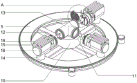
Fig. 1 is a schematic structural view of a valve processing apparatus for sewage treatment.
Fig. 2 is a schematic structural view of a movable shaft seat in a valve machining device for sewage treatment.
Fig. 3 is an enlarged schematic view of a portion a of a valve processing apparatus for sewage treatment.
In the figure: 1. a work table; 2. a support; 3. an electric hydraulic rod I; 4. a rubber pad; 5. a movable shaft seat; 6. a tooth socket; 7. a gear; 8. a first motor; 9. cleaning the hole; 10. processing a base; 11. processing a tank; 12. a support bar; 13. a valve body; 14. fixing the rod; 15. a body; 16. a second electric hydraulic rod; 17. a second motor; 18. a slider; 19. mounting a disc; 20. a scraper; 21. a chuck; 22. a screw hole; 23. a bolt; 24. a dust collecting groove; 25. a vacuum cleaner; 26. a dust collection box; 27. supporting legs; 28. and a controller.
Detailed Description
The technical solutions in the embodiments of the present invention will be described clearly and completely with reference to the accompanying drawings in the embodiments of the present invention, and it is obvious that the described embodiments are only some embodiments of the present invention, not all embodiments. Based on the embodiments in the present invention, all other embodiments obtained by a person skilled in the art without creative work belong to the protection scope of the present invention.
Referring to fig. 1 to 3, in an embodiment of the present invention, a valve processing device for sewage treatment includes a workbench 1, a support 2 is installed on a surface of the workbench 1, a first electric hydraulic rod 3 is installed on the support 2, a rubber pad 4 is installed on the first electric hydraulic rod 3, a movable shaft seat 5 is installed on an inner side of the support 2, a slot is formed in the movable shaft seat 5 and provided with a tooth slot 6, a plurality of gears 7 are engaged with one side of the tooth slot 6, a plurality of gears 7 are connected with a first motor 8, and a plurality of first motors 8 are fixed on the workbench 1;
a hole is formed in the movable shaft seat 5 and provided with a cleaning hole 9, the cleaning hole 9 penetrates through the workbench 1, a processing seat 10 is arranged in the cleaning hole 9, a groove is formed in the processing seat 10 and provided with a processing groove 11, a valve body 13 is arranged in the processing groove 11, a plurality of support rods 12 are fixed on the side wall of the bottom of the processing seat 10, and the processing seat 10 is fixed on the workbench 1 through the plurality of support rods 12;
the surface of the movable shaft seat 5 is provided with a plurality of fixing rods 14, a machine body 15 is arranged on each fixing rod 14, the interior of the machine body 15 is hollow and is provided with a second electric hydraulic rod 16, one end of the second electric hydraulic rod 16 is fixed in the machine body 15, the other end of the second electric hydraulic rod 16 is fixedly provided with a second motor 17, a sliding block 18 is arranged on the second motor 17, and the top surface of the machine body 15 is provided with a groove and a plurality of sliding grooves;
the sliding block 18 on the second motor 17 is limited in a sliding groove on the machine body 15 in a sliding mode, a mounting disc 19 is mounted at one end of the second motor 17, a groove is formed in the mounting disc 19, a scraper 20 is arranged in the groove, holes are formed in the scraper 20 and the machine body 15, a chuck 21 is arranged in the hole, a screw hole 22 is formed in the chuck 21, a bolt 23 is arranged in the screw hole 22, four supporting legs 27 are mounted at four corners of the bottom of the workbench 1, the number of the supporting legs 27 is four, and a controller 28 is mounted on the outer side wall of one end of the support 2;
a dust collecting groove 24 is arranged below the cleaning hole 9, one end of the dust collecting groove 24 is hermetically connected to the workbench 1, the other end of the dust collecting groove 24 is connected with a dust collector 25, the top end of the dust collector 25 is hermetically connected to the dust collecting groove 24, and one side of the dust collector 25 is connected with a dust collecting box 26.
The utility model discloses a theory of operation is:
the utility model discloses, during processing, the valve body 13 that need to be cut and polished for sewage treatment is placed on the processing groove 11 on the processing seat 10, when the valve body 13 is placed on the processing groove 11, the electric hydraulic rod one 3 is started through the controller 28, the electric hydraulic rod one 3 descends to clamp the valve body 13 on the processing seat 10 through the rubber pad 4, thereby fixing the valve body 13 that needs to be processed, facilitating cutting and polishing;
when the valve body 13 is polished, the surface of the fixed valve body 13 which needs to be cut and polished is located on one surface of the scraper 20, when the second motor 17 is started through the controller 28, the second motor 17 rotates to drive the scraper 20 on the mounting disc 19 to rotate, and the scraper 20 rotates along the track of the outer diameter of the valve body 13 to perform polishing work;
when cleaning, the valve body 13 is polished and the dust collector 25 is started, and when the dust collector 25 works, metal scraps and other powder are sucked into the dust collector 25 through the dust collecting groove 24 and then discharged into the dust collecting box 26, so that the scraps are conveniently collected and cleaned.
The above, only be the concrete implementation of the preferred embodiment of the present invention, but the protection scope of the present invention is not limited thereto, and any person skilled in the art is in the technical scope of the present invention, according to the technical solution of the present invention and the utility model, the concept of which is equivalent to replace or change, should be covered within the protection scope of the present invention.
Claims (6)
1. The valve machining device for sewage treatment comprises a workbench (1), and is characterized in that a support (2) is mounted on the surface of the workbench (1), a first electric hydraulic rod (3) is mounted on the support (2), a rubber pad (4) is mounted on the first electric hydraulic rod (3), a movable shaft seat (5) is arranged on the inner side of the support (2), a groove is formed in the movable shaft seat (5) and provided with a tooth groove (6), a plurality of gears (7) are meshed with one side of the tooth groove (6), a first motor (8) is connected to each of the gears (7), and the first motors (8) are fixed on the workbench (1);
the movable shaft seat (5) is internally provided with a hole and a cleaning hole (9), the cleaning hole (9) penetrates through the workbench (1), a processing seat (10) is arranged in the cleaning hole (9), a groove is formed in the processing seat (10) and a processing groove (11) is formed in the processing seat (10), a valve body (13) is arranged in the processing groove (11), a plurality of supporting rods (12) are fixed on the side wall of the bottom of the processing seat (10), and the processing seat (10) is fixed on the workbench (1) through the plurality of supporting rods (12);
the utility model discloses a hydraulic motor, including activity axle bed (5), movable shaft bed (5) and motor, install a plurality of dead levers (14) on the surface, it is a plurality of, a plurality of fuselage (15) all are installed on dead lever (14), fuselage (15) are inside to be hollow and to install electronic hydraulic stem two (16), and electronic hydraulic stem two (16) one end is fixed inside fuselage (15), and electronic hydraulic stem two (16) other end is fixed with motor two (17), install slider (18) on motor two (17), the top of fuselage (15) is slotted on the surface and is equipped with a plurality of spouts.
2. The valve processing device for sewage treatment according to claim 1, wherein the sliding block (18) on the second motor (17) is limited in a sliding groove on the machine body (15) in a sliding manner, and a mounting disc (19) is mounted at one end of the second motor (17).
3. The valve processing device for sewage treatment according to claim 2, wherein the mounting plate (19) is grooved and provided with a scraper (20), the scraper (20) and the body (15) are both provided with holes and provided with a chuck (21), the chuck (21) is provided with holes and provided with a screw hole (22), and the screw hole (22) is provided with a bolt (23).
4. The valve processing device for sewage treatment according to claim 1, wherein four supporting feet (27) are respectively installed at four corners of the bottom of the workbench (1), the number of the supporting feet (27) is four, and a controller (28) is installed on the outer side wall of one end of the support (2).
5. The valve processing device for sewage treatment according to claim 1, wherein a dust collecting groove (24) is arranged below the cleaning hole (9), one end of the dust collecting groove (24) is hermetically connected to the workbench (1), and the other end of the dust collecting groove (24) is connected with a dust collector (25).
6. The valve processing device for sewage treatment as claimed in claim 5, wherein the top end of the dust collector (25) is hermetically connected to the dust collection groove (24), and one side of the dust collector (25) is connected to the dust collection box (26).
Priority Applications (1)
| Application Number | Priority Date | Filing Date | Title |
|---|---|---|---|
| CN202023243400.5U CN214641700U (en) | 2020-12-29 | 2020-12-29 | Valve machining device for sewage treatment |
Applications Claiming Priority (1)
| Application Number | Priority Date | Filing Date | Title |
|---|---|---|---|
| CN202023243400.5U CN214641700U (en) | 2020-12-29 | 2020-12-29 | Valve machining device for sewage treatment |
Publications (1)
| Publication Number | Publication Date |
|---|---|
| CN214641700U true CN214641700U (en) | 2021-11-09 |
Family
ID=78504308
Family Applications (1)
| Application Number | Title | Priority Date | Filing Date |
|---|---|---|---|
| CN202023243400.5U Expired - Fee Related CN214641700U (en) | 2020-12-29 | 2020-12-29 | Valve machining device for sewage treatment |
Country Status (1)
| Country | Link |
|---|---|
| CN (1) | CN214641700U (en) |
Cited By (1)
| Publication number | Priority date | Publication date | Assignee | Title |
|---|---|---|---|---|
| CN120115429A (en) * | 2025-03-27 | 2025-06-10 | 苏州市凯兹阀门有限公司 | A valve deoiling and degreasing treatment process and equipment |
-
2020
- 2020-12-29 CN CN202023243400.5U patent/CN214641700U/en not_active Expired - Fee Related
Cited By (1)
| Publication number | Priority date | Publication date | Assignee | Title |
|---|---|---|---|---|
| CN120115429A (en) * | 2025-03-27 | 2025-06-10 | 苏州市凯兹阀门有限公司 | A valve deoiling and degreasing treatment process and equipment |
Similar Documents
| Publication | Publication Date | Title |
|---|---|---|
| CN210756901U (en) | Polishing device for glass plates | |
| CN116276518A (en) | A central control shell grinding production line and grinding method | |
| CN211589591U (en) | Mould processing grinding device | |
| CN214867539U (en) | Dust collector is used in milling machine processing | |
| CN112743350A (en) | Novel engraving and milling equipment | |
| CN217122797U (en) | Dustless polishing equipment in metal product surface | |
| CN219945259U (en) | Rotating device of horizontal machining center | |
| CN218194195U (en) | A trimming device for plastic mold processing with a dust removal assembly | |
| CN218194407U (en) | Multifunctional auxiliary rough machining equipment for mechanical parts | |
| CN222520996U (en) | A lithium battery sealing gasket processing device | |
| CN214445197U (en) | Sheet metal deburring device convenient to adjust | |
| CN213917063U (en) | High-speed numerical control engraving and milling machine support base convenient to garbage collection | |
| CN214265113U (en) | Automobile parts burnishing device | |
| CN213105954U (en) | Suit door rough machining grinding device | |
| CN210633453U (en) | Polishing and grinding device for stamping parts | |
| CN221621691U (en) | Chamfering grinding tool for die machining | |
| CN209394048U (en) | A high-speed engraving and milling machine for a machine tool | |
| CN221109305U (en) | Sculpture fine repair dust removal cleaning device | |
| CN221560806U (en) | A grinding device for plastic products | |
| CN217371669U (en) | Diamond chamfering device with spiral groove | |
| CN222059667U (en) | A CNC gantry milling machine that is easy to clean debris | |
| CN220217679U (en) | Aluminum product processing sweeps collecting device | |
| CN216371421U (en) | Stone rough grinding machine | |
| CN218283887U (en) | Numerical control milling machine | |
| CN214392431U (en) | Valve flange multiaxis drilling equipment that machining efficiency is high |
Legal Events
| Date | Code | Title | Description |
|---|---|---|---|
| GR01 | Patent grant | ||
| GR01 | Patent grant | ||
| CF01 | Termination of patent right due to non-payment of annual fee | ||
| CF01 | Termination of patent right due to non-payment of annual fee |
Granted publication date: 20211109 |