Circuit board and driving power supply with same
Technical Field
The utility model relates to a drive power supply heat dissipation technical field, especially a circuit board and drive power supply who has this circuit board.
Background
At present, electronic products are widely used, and the electronic products cannot be powered on, but a driving power supply (a switching power supply) is required to be used for connecting the electronic products with mains supply to supply power to the electronic products. The driving power supply comprises a shell and a PCB arranged in the shell, the lower end face of the PCB is generally tightly attached to the inner wall face of the shell, and the heat dissipation effect is poor.
In order to solve the above problems, for a power device which generates heat seriously during operation, a conventional method is to mount a heat sink on the heat-generating power device, and the heat sink and the power device are fastened together by screws or insulating heat conducting pads, and this method is generally implemented manually, and has the defects of possible damage to the power device, low production efficiency, more manpower usage, and the like.
SUMMERY OF THE UTILITY MODEL
In view of this, the present invention provides a circuit board and a driving power supply having the same to solve the above technical problems.
A circuit board comprises a mainboard with base materials made of insulating materials and at least one metal-based copper-clad plate, wherein each metal-based copper-clad plate is provided with at least one component and a pin connected with the mainboard.
Preferably, the metal base of the metal-base copper-clad plate is grounded.
Preferably, the metal-based copper-clad plate comprises an aluminum base layer, an insulating layer and a copper foil layer.
Preferably, the metal-based copper-clad plate is provided with a through hole, the through hole is provided with a weldable rivet, one end of the rivet is electrically connected with the aluminum base layer, the other end of the rivet is connected with the copper foil layer through soldering tin, and then the copper foil layer is directly or indirectly connected with the main board to enable the aluminum base layer to be grounded.
Preferably, the metal-based copper-clad plate is copper-based and comprises a copper base layer, an insulating layer and a copper foil layer.
Preferably, the copper base layer is soldered to the "ground" of the main board.
Preferably, the component is a power device.
A driving power supply includes a power supply box and a circuit board disposed in the power supply box.
The technical effects of the utility model:
the circuit board and the driving power supply with the circuit board have the advantages that the structure is simple, the manufacturing cost is low, the automatic manufacturing is convenient, the power device can be directly attached to the metal substrate through the automatic equipment, the metal substrate can realize the function of the radiator, the production efficiency is improved, and the hidden danger of the quality of the manufacturing process is reduced; meanwhile, the grounding problem of the metal substrate is solved, and the EMC problem is avoided.
Drawings
Embodiments of the present invention are described below with reference to the accompanying drawings, in which:
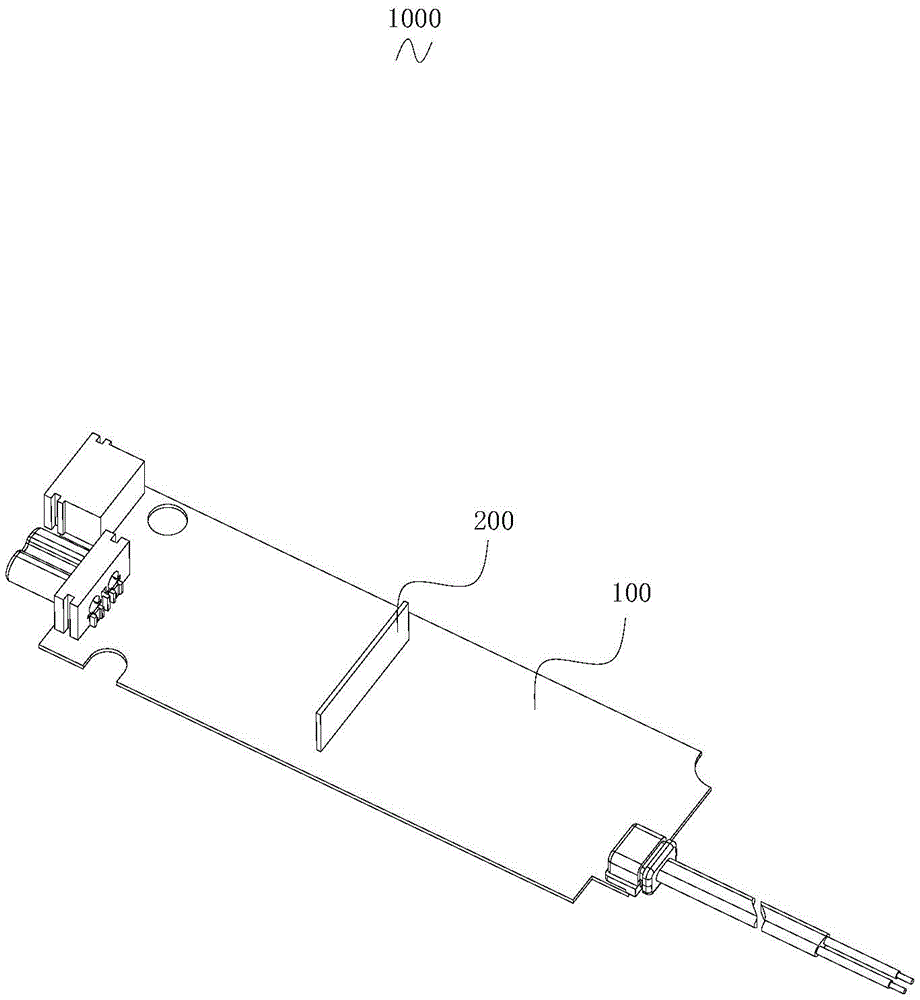
fig. 1 is a schematic structural diagram of the circuit board of the present embodiment.
Fig. 2 is a schematic structural diagram of the metal-based copper-clad plate of the present embodiment.
Fig. 3 is a schematic cross-sectional view of the metal-based copper-clad plate of this embodiment at a rivet.
Fig. 4 is a schematic structural diagram of a metal-based copper-clad plate according to another embodiment.
Fig. 5 is a schematic cross-sectional view of another embodiment of a metal-based copper-clad plate.
Fig. 6 is a cross-sectional schematic view of the driving power supply of the present embodiment.
Detailed Description
The following describes in further detail specific embodiments of the present invention based on the drawings. It should be understood that the description herein of embodiments of the invention is not intended to limit the scope of the invention.
As shown in fig. 1 to 3, the circuit board 1000 of the present embodiment includes a main board 100 whose base material is made of insulating material and at least one metal-based copper-clad board 200.
The substrate of the motherboard 100 is generally classified by the insulation part of the substrate, and the common raw materials are bakelite board, glass fiber board, and various plastic boards. Manufacturers generally use an insulating part composed of glass fiber, non-woven material and resin, and then press epoxy resin and copper foil into an adhesive sheet (prepreg), so that the manufacturing cost is low and the application range is wide.
The utility model discloses the metal-based Copper-Clad plate 200 of well adoption is one kind of Copper-Clad Laminate, and the single-sided board just adopts the metal base, and Copper-Clad Laminate (Copper Clad Laminate, CCL) is with the Copper foil and through the plate material that hot pressing and make, Copper-Clad plate for short. Various printed circuit boards with different forms and different functions are manufactured into different printed circuits by selectively carrying out the working procedures of processing, etching, drilling, copper plating and the like on a copper-clad plate. The copper clad laminate can be divided into an organic resin copper clad laminate, a metal-based (core) copper clad laminate and a ceramic-based copper clad laminate according to different insulating materials and structures of the copper clad laminate. The metal-based copper clad laminate 200 generally has a single-sided board composed of three layers, namely a copper foil layer (circuit layer), an insulating layer and a metal base layer.
Each metal-based copper-clad plate 200 is provided with at least one component 300 and a pin 201 connected with the motherboard 100. The quantity of pin 201 can set up according to circuit structure, and connected mode adopts pin and picture peg hole welding, for prior art unreinforced, the utility model discloses a metal-based copper-clad plate 200 switches on with mainboard 100 and forms complete circuit. In the present embodiment, such components are directly attached to the metal-based copper-clad plate 200 through automation equipment, and then interconnected with the motherboard 100 through the pins 201. In the embodiment, the metal-based copper-clad plate 200 can simultaneously complete the function of the radiator, thereby improving the production efficiency and reducing the hidden quality trouble.
Since the power devices with more severe heat generation generally operate in a switching state and the switching signal causes EMC problems, it is generally necessary to ground the heat sink to change the coupling path of the EMC. Preferably, the metal base of the metal-based copper-clad plate 200 is grounded. The utility model discloses the EMC problem that the switching signal of having solved power device arouses on realizing automatic paster technical basis. Grounding in electronic equipment is generally understood to be both direct connection to the power grid ground and connection to the "ground" (electrical quiescent point) within the electronic circuit. For the application of the metal-based copper-clad plate 200 that needs to be electrically connected to the motherboard 100, the second method is more common, but the first method is also applicable, and how to implement the electrical connection is not repeated in the prior art.
In this embodiment, the metal-based copper clad laminate 200 includes an aluminum base layer 202, an insulating layer 203, and a copper foil layer 204. The aluminum substrate is a metal-based copper-clad plate with a good heat dissipation function, and is relatively common and low in purchase cost.
The aluminum base layer 202 and the copper foil layer 204 of the aluminum base plate are separated by an insulating medium (an insulating layer 203) to realize the insulation between different electric circuits of the copper foil layer 204. Since the aluminum base layer 202 is made of aluminum and direct soldering to copper is not possible, another method is required to ground the aluminum base layer 202. The utility model discloses a realize through the rivet mode, concrete scheme is as follows: the specific structure is that a through hole 205 is formed in the metal-based copper-clad plate 200, a weldable rivet 206 is arranged in the through hole 205, one end of the rivet 206 is electrically connected with the aluminum base layer 202, the other end of the rivet 206 is connected with the copper foil layer 204 through soldering tin, and the copper foil layer 204 is directly or indirectly connected with the main plate 100 so as to enable the aluminum base layer 202 to be grounded.
In this embodiment, the metal-based copper-clad plate 200 is provided with one piece, and 5 components 300 are attached to the piece.
In addition to aluminum substrate, copper substrate may be used, as shown in fig. 4 and 5, and in another embodiment, the metal-based copper clad laminate 200 'is copper-based, and includes a copper-based layer 202', an insulating layer 203 'and a copper foil layer 204'. The copper base layer 202 'of the copper substrate can be directly electrically connected with the motherboard 100, and the copper base layer 202' is soldered with the ground of the motherboard 100.
The utility model discloses dissipation power can reach the heat dissipation problem of the components and parts more than the W level in to the circuit, components and parts 300 are power device. Specifically, the component 300 is a MOS transistor, a diode, or other power device.
As shown in fig. 6, the driving power supply of the present embodiment includes a power supply box 2000 and a circuit board 1000 disposed in the power supply box 2000. The power supply box 2000 may have a conventional structure, including input and output components, which are not described herein in detail in the prior art.
The above description is only for the preferred embodiment of the present invention and should not be construed as limiting the scope of the present invention, and any modification, equivalent replacement or improvement within the spirit of the present invention is encompassed by the claims of the present invention.