CN214575513U - Building platform of adjustable interior decoration building - Google Patents
Building platform of adjustable interior decoration building Download PDFInfo
- Publication number
- CN214575513U CN214575513U CN202120243710.2U CN202120243710U CN214575513U CN 214575513 U CN214575513 U CN 214575513U CN 202120243710 U CN202120243710 U CN 202120243710U CN 214575513 U CN214575513 U CN 214575513U
- Authority
- CN
- China
- Prior art keywords
- building
- box body
- servo motor
- fixedly connected
- rod
- Prior art date
- Legal status (The legal status is an assumption and is not a legal conclusion. Google has not performed a legal analysis and makes no representation as to the accuracy of the status listed.)
- Expired - Fee Related
Links
- 238000005034 decoration Methods 0.000 title claims abstract description 15
- 230000013011 mating Effects 0.000 claims 1
- 239000000463 material Substances 0.000 abstract description 4
- 229910001220 stainless steel Inorganic materials 0.000 abstract description 2
- 239000010935 stainless steel Substances 0.000 abstract description 2
- 230000002457 bidirectional effect Effects 0.000 description 13
- 238000010276 construction Methods 0.000 description 5
- 230000000694 effects Effects 0.000 description 4
- 230000005484 gravity Effects 0.000 description 3
- 238000010586 diagram Methods 0.000 description 2
- 230000000630 rising effect Effects 0.000 description 2
- 229910000831 Steel Inorganic materials 0.000 description 1
- 238000007792 addition Methods 0.000 description 1
- 230000003111 delayed effect Effects 0.000 description 1
- 230000004048 modification Effects 0.000 description 1
- 238000012986 modification Methods 0.000 description 1
- 239000010959 steel Substances 0.000 description 1
- 238000006467 substitution reaction Methods 0.000 description 1
- 238000012876 topography Methods 0.000 description 1
Images


Abstract
The utility model relates to a building decoration auxiliary assembly technical field, concretely relates to building platform of adjustable interior decoration building, including hoist mechanism and supporting mechanism, hoist mechanism includes box, fixed plate and servo motor, it is connected with two-way lead screws to rotate between the two short inside walls of box, the both ends of two-way lead screw all close soon and are connected with the go-between, the top of go-between is rotated and is connected with the one end of connecting rod, the other end of connecting rod is provided with supporting mechanism. The utility model discloses in, can realize the stable lift of roof through starting servo motor, the structure of whole device mostly uses the stainless steel as the main material moreover, and weight is lighter, and the constructor of being convenient for removes, and the practicality is strong, can greatly alleviate constructor's physical demands and the fitment degree of difficulty.
Description
Technical Field
The utility model relates to a building decoration auxiliary assembly technical field, concretely relates to building platform of adjustable interior decoration building.
Background
The decoration is an indispensable part in people's life, and the effect of decoration is that the major structure of protection building, perfect the performance of building, beautify the building etc. when the workman decorates indoor outer, often need use supporting platform to the convenience is under construction higher department.
The existing supporting platform is simple in structure, steel pipes are generally used for splicing, the weight is large, the indoor and outdoor moving is inconvenient, the progress of construction is greatly delayed, the height of the existing supporting platform is generally fixed, the appropriate height cannot be selected according to real-time construction conditions, and the use of users is not facilitated.
SUMMERY OF THE UTILITY MODEL
In order to overcome foretell technical problem, an object of the utility model is to provide a building platform of adjustable interior decoration building, servo motor has been linked firmly through the inner chamber bottom surface middle part at the box, servo motor's output cup joints and is fixed with the fourth helical gear, and it is connected with two-way lead screws to rotate between the two short inside walls of box, the both ends of two-way lead screw all close soon and are connected with the go-between, the top of go-between is rotated and is connected with the one end of connecting rod, make the go-between remove along two-way lead screw through starting servo motor, and then accomplish the lift of roof, constructor's physical demands has been saved, and the invariable controllable lifting speed, avoid standing the personnel of roof construction because the unstable accident that takes place of focus, reliability and security all can improve.
The purpose of the utility model can be realized by the following technical scheme:
a building platform capable of adjusting interior decoration buildings comprises a lifting mechanism and a supporting mechanism, wherein the lifting mechanism comprises a box body, fixing plates and a servo motor, two bidirectional screw rods are rotatably connected between two short inner side walls of the box body, two ends of each bidirectional screw rod are rotatably connected with connecting rings, the top ends of the connecting rings are rotatably connected with one ends of connecting rods, the other ends of the connecting rods are provided with the supporting mechanism, first bevel gears are fixedly sleeved in the middle of the bidirectional screw rods, the two fixing plates are fixedly connected to the middle of the bottom surface of an inner cavity of the box body in a symmetrical mode about a vertical central plane of the middle of the bottom surface of the inner cavity of the box body, a rotating shaft is rotatably connected between the two fixing plates, second bevel gears are fixedly sleeved in the middle of the rotating shaft, two ends of the rotating shaft penetrate through the fixing plates and are fixedly sleeved with third bevel gears, and the third bevel gears are mutually meshed with the adjacent first bevel gears, the middle part of the bottom surface of the inner cavity of the box body is fixedly connected with a servo motor, the output end of the servo motor is fixedly connected with a fourth bevel gear in a sleeved mode, the lifting of the top plate is completed by starting the servo motor, the physical consumption of constructors is saved, the lifting speed is constant and controllable, and accidents of the constructors standing on the top plate due to unstable gravity center are avoided.
Further, the fourth bevel gear and the second bevel gear are meshed with each other and are matched components, so that the servo motor drives the rotating shaft to rotate.
Further lie in, supporting mechanism includes the roof and accomodates the pole, four end angles of roof bottom surface have all linked firmly the engaging lug, the engaging lug rotates the other end that is connected with the connecting rod, four end angles of roof top surface have all linked firmly the fixed block, have linked firmly the fixed axle between two adjacent fixed blocks, the outer wall of fixed axle rotates and has cup jointed the one end of railing, before the roof rises, can rotate the railing, plays the effect of protection constructor safety.
Further lie in, four end angles of box bottom surface all link firmly the universal wheel, a lateral wall middle part of box has linked firmly the handle, when indoor needs remove the device, can play the effect at each room quick travel through the universal wheel, when needs change the floor or face complicated topography, can carry away whole device through the pulling handle.
Further lie in, the inside wall of fixed block is provided with the dog with the adjacent department of railing to it is excessive to avoid the railing upset.
Further lie in, a long lateral wall middle part of roof has linked firmly two and has accomodate the pole, the inner chamber of accomodating the pole slides and has cup jointed the one end of first telescopic link, the other end inner chamber of first telescopic link slides and has cup jointed the second telescopic link, the bottom of second telescopic link has linked firmly the inner chamber bottom surface of box, has all linked firmly the round bar between two adjacent inside walls of accomodating pole and first telescopic link and second telescopic link to the constructor of being convenient for is roof from top to bottom.
The utility model has the advantages that:
1. the middle part of the bottom surface of the inner cavity of the box body is fixedly connected with a servo motor, the output end of the servo motor is fixedly sleeved with a fourth bevel gear, two bidirectional screw rods are rotatably connected between two short inner side walls of the box body, two ends of each bidirectional screw rod are rotatably connected with a connecting ring, the top end of each connecting ring is rotatably connected with one end of a connecting rod, the connecting rings move along the bidirectional screw rods by starting the servo motor, so that the lifting of the top plate is completed, the physical consumption of constructors is saved, the lifting speed is constant and controllable, accidents caused by unstable gravity center of the constructors standing on the top plate are avoided, and the reliability and the safety are improved;
2. through having linked firmly two and accomodate the pole at a long lateral wall middle part of roof, the inner chamber of accomodating the pole slides and has cup jointed the one end of first telescopic link, the second telescopic link has been cup jointed in the other end inner chamber of first telescopic link slides, the bottom of second telescopic link has linked firmly the inner chamber bottom surface of box, two are accomodate the pole and all have linked firmly the round bar between the double-phase adjacent inside wall of first telescopic link and second telescopic link, thereby be convenient for constructor roof from top to bottom, the flexible length of telescopic link and the rising height phase-match of ejector pin, can realize the stable lift of roof through starting servo motor, and the structure of whole device mostly uses the stainless steel as the main material, light in weight, the constructor of being convenient for removes, therefore, the clothes hanger is strong in practicability, constructor's physical demands and the fitment degree of difficulty can greatly be alleviateed.
Drawings
The present invention will be further described with reference to the accompanying drawings.
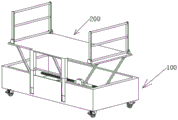
Fig. 1 is a schematic view of the overall structure of the present invention;
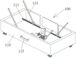
FIG. 2 is a schematic view of the working structure of the present invention;
fig. 3 is a schematic structural diagram of a lifting mechanism of the present invention;
FIG. 4 is a schematic structural view of the two-way screw rod of the present invention;
FIG. 5 is an enlarged view of a portion of FIG. 4 at A;
fig. 6 is a schematic structural diagram of the supporting mechanism of the present invention;
FIG. 7 is a partial enlarged view at B in FIG. 6;
fig. 8 is a schematic view of the bottom structure of the middle top plate of the present invention.
In the figure: 100. a lifting mechanism; 110. a box body; 111. a bidirectional screw rod; 112. a connecting ring; 113. a connecting rod; 114. a first helical gear; 115. a handle; 120. a fixing plate; 121. a rotating shaft; 122. a second helical gear; 123. a third bevel gear; 130. a servo motor; 131. a fourth helical gear; 200. a support mechanism; 210. a top plate; 211. connecting lugs; 212. a fixed block; 213. a fixed shaft; 214. a railing; 220. a storage rod; 221. a first telescopic rod; 222. and a second telescopic rod.
Detailed Description
The technical solutions in the embodiments of the present invention will be described clearly and completely below with reference to the embodiments of the present invention, and it is obvious that the described embodiments are only some embodiments of the present invention, not all embodiments. Based on the embodiments of the present invention, all other embodiments obtained by a person of ordinary skill in the art without creative efforts belong to the protection scope of the present invention.
Referring to fig. 1-8, a building platform for adjusting interior decoration buildings comprises a lifting mechanism 100 and a supporting mechanism 200, wherein the lifting mechanism 100 comprises a box body 110, a fixing plate 120 and a servo motor 130, two bidirectional screws 111 are rotatably connected between two short inner side walls of the box body 110, two ends of each bidirectional screw 111 are rotatably connected with a connecting ring 112, the top end of each connecting ring 112 is rotatably connected with one end of a connecting rod 113, the other end of each connecting rod 113 is provided with the supporting mechanism 200, a first helical gear 114 is fixedly sleeved in the middle of each bidirectional screw 111, two fixing plates 120 are symmetrically and fixedly connected with the middle of the bottom surface of an inner cavity of the box body 110 about the vertical central plane thereof, a rotating shaft 121 is rotatably connected between the two fixing plates 120, a second helical gear 122 is fixedly sleeved in the middle of the rotating shaft 121, two ends of each rotating shaft 121 penetrate through the fixing plates 120 and are fixedly sleeved with a third helical gear 123, the third helical gear 123 is engaged with the adjacent first helical gear 114, the middle part of the bottom surface of the inner cavity of the box body 110 is fixedly connected with the servo motor 130, the output end of the servo motor 130 is fixedly connected with the fourth bevel gear 131 in a sleeved mode, the servo motor 130 is started to complete the lifting of the top plate 210, physical consumption of constructors is saved, the lifting speed is constant and controllable, and accidents caused by unstable gravity center of the constructors standing on the top plate 210 are avoided.
The fourth bevel gear 131 and the second bevel gear 122 are engaged with each other, and they are matched components, so that the servo motor 130 drives the rotating shaft 121 to rotate, the supporting mechanism 200 comprises a top plate 210 and a containing rod 220, four end corners of the bottom surface of the top plate 210 are fixedly connected with connecting lugs 211, the connecting lugs 211 are rotatably connected with the other end of the connecting rod 113, four end corners of the top surface of the top plate 210 are fixedly connected with fixing blocks 212, a fixing shaft 213 is fixedly connected between two adjacent fixing blocks 212, the outer wall of the fixing shaft 213 is rotatably sleeved with one end of a rail 214, before the top plate 210 rises, the rail 214 can be rotated to play a role of protecting safety of constructors, four end corners of the bottom surface of the box body 110 are fixedly connected with universal wheels, a handle 115 is fixedly connected with the middle part of a side wall of the box body 110, when the device needs to be moved indoors, the effect of fast moving in each room can be achieved through the universal wheels, when floors need to be changed or when complex terrains are faced, the entire device can be lifted away by pulling on the handle 115.
The inside wall of fixed block 212 is provided with the dog with railing 214's adjacent department, thereby it is excessive to avoid railing 214 to overturn, a long lateral wall middle part of roof 210 has linked firmly two and has accomodate pole 220, the one end of first telescopic link 221 has been cup jointed in the inner chamber slip of accomodating pole 220, the other end inner chamber slip of first telescopic link 221 has cup jointed second telescopic link 222, the bottom of second telescopic link 222 has linked firmly the inner chamber bottom surface of box 110, two are accomodate and all have been linked firmly the round bar between the double-phase adjacent inside wall of pole 220 and first telescopic link 221 and second telescopic link 222, thereby be convenient for constructor roof 210 from top to bottom.
The working principle is as follows: when the bidirectional screw rod 111 rotates, the connecting ring 112 on the bidirectional screw rod 111 moves towards the short side wall of the box body 110 along the bidirectional screw rod 111, the connecting rod 113 rotatably connected with the connecting ring 112 rotates to lift the top plate 210, the first telescopic rod 221 slides out of the inner cavity of the accommodating rod 220 along with the lifting of the top plate 210, the second telescopic rod 222 slides out of the inner cavity of the first telescopic rod 221, when a constructor feels a proper height, the servo motor 130 may be turned off, at which time the top plate 210 stops rising, and the constructor may climb the round bar to climb the top plate 210 for construction.
In the description herein, references to the description of "one embodiment," "an example," "a specific example," etc., mean that a particular feature, structure, material, or characteristic described in connection with the embodiment or example is included in at least one embodiment or example of the invention. In this specification, the schematic representations of the terms used above do not necessarily refer to the same embodiment or example. Furthermore, the particular features, structures, materials, or characteristics described may be combined in any suitable manner in any one or more embodiments or examples.
The foregoing is illustrative and explanatory only, and various modifications, additions and substitutions as described for the specific embodiments described herein may be made by those skilled in the art without departing from the scope of the invention or exceeding the scope of the invention as defined in the claims.
Claims (6)
1. The building platform capable of adjusting the interior decoration building comprises a lifting mechanism (100) and a supporting mechanism (200), and is characterized in that the lifting mechanism (100) comprises a box body (110), a fixing plate (120) and a servo motor (130), two-way screw rods (111) are rotatably connected between two short inner side walls of the box body (110), two ends of each two-way screw rod (111) are rotatably connected with a connecting ring (112), the top end of each connecting ring (112) is rotatably connected with one end of a connecting rod (113), the other end of each connecting rod (113) is provided with the supporting mechanism (200), the middle of each two-way screw rod (111) is fixedly sleeved with a first bevel gear (114), the middle of the bottom surface of an inner cavity of the box body (110) is symmetrically and fixedly connected with two fixing plates (120) about a vertical central plane of the middle part of the bottom surface of the inner cavity of the box body (110), and a rotating shaft (121) is rotatably connected between the two fixing plates (120), the middle part of pivot (121) is cup jointed and is fixed with second helical gear (122), the both ends of pivot (121) all run through fixed plate (120) and cup joint and be fixed with third helical gear (123), third helical gear (123) and its adjacent first helical gear (114) intermeshing, the inner chamber bottom surface middle part of box (110) has linked firmly servo motor (130), the output cup joint of servo motor (130) is fixed with fourth helical gear (131).
2. A building platform for an adjustable interior finishing building according to claim 1, wherein the fourth bevelled gear (131) and the second bevelled gear (122) are engaged with each other as mating members.
3. The building platform of an adjustable interior decoration building of claim 1, wherein, the supporting mechanism (200) comprises a top plate (210) and a receiving rod (220), four end corners of the bottom surface of the top plate (210) are all fixedly connected with a connecting lug (211), the connecting lug (211) is rotatably connected with the other end of the connecting rod (113), four end corners of the top surface of the top plate (210) are all fixedly connected with a fixing block (212), a fixing shaft (213) is fixedly connected between two adjacent fixing blocks (212), and the outer wall of the fixing shaft (213) is rotatably sleeved with one end of a railing (214).
4. The building platform for the adjustable interior decoration of claim 1, wherein the universal wheels are attached to four corners of the bottom surface of the box body (110), and the handle (115) is attached to the middle of one side wall of the box body (110).
5. A building platform for an adjustable interior finishing building as claimed in claim 3, wherein the block (212) has a stop on its inner side wall adjacent the rail (214).
6. The building platform for the adjustable interior decoration building of claim 3, wherein two receiving rods (220) are fixedly connected to the middle of one long side wall of the top plate (210), the inner cavity of each receiving rod (220) is slidably sleeved with one end of a first telescopic rod (221), the inner cavity of the other end of each first telescopic rod (221) is slidably sleeved with a second telescopic rod (222), and the bottom end of each second telescopic rod (222) is fixedly connected with the bottom surface of the inner cavity of the box body (110).
Priority Applications (1)
| Application Number | Priority Date | Filing Date | Title |
|---|---|---|---|
| CN202120243710.2U CN214575513U (en) | 2021-01-28 | 2021-01-28 | Building platform of adjustable interior decoration building |
Applications Claiming Priority (1)
| Application Number | Priority Date | Filing Date | Title |
|---|---|---|---|
| CN202120243710.2U CN214575513U (en) | 2021-01-28 | 2021-01-28 | Building platform of adjustable interior decoration building |
Publications (1)
| Publication Number | Publication Date |
|---|---|
| CN214575513U true CN214575513U (en) | 2021-11-02 |
Family
ID=78314677
Family Applications (1)
| Application Number | Title | Priority Date | Filing Date |
|---|---|---|---|
| CN202120243710.2U Expired - Fee Related CN214575513U (en) | 2021-01-28 | 2021-01-28 | Building platform of adjustable interior decoration building |
Country Status (1)
| Country | Link |
|---|---|
| CN (1) | CN214575513U (en) |
-
2021
- 2021-01-28 CN CN202120243710.2U patent/CN214575513U/en not_active Expired - Fee Related
Similar Documents
| Publication | Publication Date | Title |
|---|---|---|
| WO2021238192A1 (en) | Liftable base for robot | |
| CN111037392B (en) | Polishing robot | |
| CN208899834U (en) | Lifting device is used in a kind of construction of interior architecture | |
| CN213654149U (en) | Aluminum climbing frame with adjustable height | |
| CN214575513U (en) | Building platform of adjustable interior decoration building | |
| CN114277926A (en) | External scalable fretwork balcony of prefabricated building | |
| CN206203779U (en) | A kind of novel electric power repairing auxiliary is ascended a height equipment | |
| CN210973592U (en) | Different-caliber corrugated pipe mixed hoisting and transporting device | |
| CN214527915U (en) | Building material safety hoisting device | |
| CN211417350U (en) | Multi-use architecture trolley | |
| CN210467275U (en) | Safety warning device for construction | |
| CN211523995U (en) | Novel building engineering scaffold | |
| CN211040758U (en) | A multi-functional street lamp for road construction | |
| CN210411275U (en) | Paint spraying device | |
| CN110344554B (en) | Concealed type deformation stair for loft type building | |
| CN210152202U (en) | Shock attenuation climbing device for construction | |
| CN110126079B (en) | Cement pier pouring device for bridge building | |
| CN112376922A (en) | Assembled steel structure sliding frame with protection function | |
| CN112520629A (en) | Building frame integrating weight lifting function | |
| CN207845074U (en) | A kind of disconnecting switch climbing operation platform | |
| CN216787873U (en) | A safe suspended structure for high altitude construction is built in room | |
| CN217949690U (en) | Companion ladder for municipal construction | |
| CN214885271U (en) | Support for building engineering | |
| CN212836593U (en) | Lifting device for fitment | |
| CN213445171U (en) | Paint produce is with throwing material device |
Legal Events
| Date | Code | Title | Description |
|---|---|---|---|
| GR01 | Patent grant | ||
| GR01 | Patent grant | ||
| CF01 | Termination of patent right due to non-payment of annual fee |
Granted publication date: 20211102 |
|
| CF01 | Termination of patent right due to non-payment of annual fee |