Cloth collecting mechanism of circular weaving machine
Technical Field
The utility model relates to a circular weaving machine technical field especially relates to a circular weaving machine receives cloth mechanism.
Background
The circular weaving machine refers to industrial equipment for weaving tubular cloth; after the circular weaving machine weaves the flat yarn into cloth, the rolling needs to be carried out, and the traditional rolling mode is through the cylinder rolling, promptly: winding the woven cloth on a roller; however, because the roller is positioned in the main machine frame, the cloth wound on the roller is limited, namely the diameter of the cloth wound on the roller is limited;
when processing big cloth in batches, use traditional cylinder to come rolling cloth, need change the cylinder, need take the cylinder down among the prior art, get new cylinder and put on again, if the cloth of cylinder epilogue is more, the workman moves motionlessly, and the less of book then leads to the cylinder extravagant, and the machine frequently opens and stops efficiency reduction, therefore we propose a circular loom and receive cloth mechanism for solve above-mentioned problem.
SUMMERY OF THE UTILITY MODEL
The utility model aims at solving the problem of inconvenient roller replacement in the prior art and providing a cloth collecting mechanism of a circular weaving machine.
In order to achieve the above purpose, the utility model adopts the following technical scheme:
the utility model provides a cloth mechanism is received to circular loom, includes the base, the cavity has been seted up on the base, top one side fixed mounting of base has the pivot frame, it is connected with the pivot to rotate on the pivot frame, sliding connection has the spring on the inner wall of cavity, the one end fixed mounting of spring has the gum piece, be equipped with switching mechanism on the inner wall of base, the top fixed mounting of base has the motor, one side of base is rotated and is connected with the drive gear, the motor is connected with drive gear drive, sliding connection has a plurality of cylinders on the inner wall of cavity, the equal fixed mounting in one side of cylinder has driven gear, driven gear cooperatees with the drive gear, and a plurality of cylinders all cooperate with switching mechanism.
Preferably, the switching mechanism comprises a push rod, a driving rod, an engaging rod, a pressing handle, a sliding plate, a driving gear, a pushing block and a partition plate, the push rod is fixedly connected with the pulling handle, the push rod is connected to the inner wall of the chamber in a sliding manner, a connecting rod is fixedly mounted on one side of the push rod, the top of one side of the connecting rod is fixedly connected with the partition plate, the partition plate is connected to the inner wall of the chamber in a sliding manner, the top of the push rod is rotatably connected with the driving rod, the top end of the driving rod is rotatably connected with the pushing block, the inner wall of the chamber is rotatably connected with the sliding plate, the inner wall of the chamber is rotatably connected with the engaging rod, the engaging rod is matched with the push rod, the top of the engaging rod is fixedly mounted with the pressing handle, the pressing handle is matched with the sliding plate, and the partition plate, the push rod, the pushing block and the sliding plate are all matched with the roller, through pulling handle pulling catch bar, catch bar pulling baffle, after the catch bar breaks away from with first cylinder, the cylinder is promoted upwards by the spring, then contact with the baffle, the catch bar still can be through driving the pole pulling catch block, withdraw the catch block, then insert the catch bar again, the catch bar inserts between first cylinder and the second cylinder, then withdraw the baffle again, then the catch bar drives the bottom that the catch block inserted first cylinder through driving the pole, the catch bar continues to enter, the catch block will be through the ascending lifting of spout upwards, and will promote the cylinder and upwards lift, first cylinder will separate with the second cylinder, when the roll-through rises to the top, just accessible motor drives and begins the rolling, the switching to the cylinder has been realized.
Preferably, a rectangular groove is formed in the push rod and is matched with the meshing rod, and the bottom end of the meshing rod is in sliding contact with the inner wall of the rectangular groove, so that the push rod can be positioned by the meshing rod.
Preferably, the slide plate is provided with a positioning groove, one side of the bottom of the pulling handle is fixedly provided with an insertion rod, the insertion rod is matched with the positioning groove, the outer side of the insertion rod is in sliding contact with the inner wall of the positioning groove, and the slide plate can be fixed when the insertion rod is inserted into the insertion groove.
Preferably, a through hole is formed in one side of the base, a roller door is connected to the inner wall of the through hole in a sliding mode, a guide frame is fixedly mounted on one side of the base and used for receiving the rolled roller, the roller can roll out along the guide frame, the end point of the guide frame can be arranged at a position where the roller is required to be stacked, the roller can be pushed in a manual mode, and the roller does not need to be carried.
Preferably, belt pulleys are fixedly mounted on one side of the driving gear and an output shaft of the motor, and the two belt pulleys are sleeved with the same belt and used for driving the driving gear to drive the driven gear to rotate, and the driven gear drives the roller.
Preferably, the top of soft glue piece is the toper structure, soft glue piece and catch plate cooperate for when the flexible glue piece promoted last cylinder, the catch bar will slide along the hypotenuse of soft glue piece toper structure after inserting, with last cylinder and flexible glue piece separation, just can not be blocked by the flexible glue piece, is being close to the inclined plane of through-hole one side simultaneously, and when filling the cylinder, first cylinder will be along the hypotenuse with the flexible glue piece down press, conveniently fills the cylinder.
The utility model has the advantages that:
1. the roller is filled in the cavity in advance, the push rod is pulled to pull the partition plate, when the push rod is separated from the first roller, the roller is pushed upwards by the spring and then contacts with the partition plate, the push rod can pull the push block through the driving rod to withdraw the push block, then the push rod is inserted into the space between the first roller and the second roller again, then the partition plate is withdrawn, then the push rod drives the push block to be inserted into the bottom of the first roller through the driving rod, the push rod continuously enters, the push block can be lifted upwards through the sliding groove and lift the push roller upwards, the first roller and the second roller can be separated, when the roller rises to the top, the driven gear on one side of the roller can be meshed with the driving gear, the motor can drive the driven gear to rotate, the driven gear drives the roller to rotate, and the roller can be started by rolling of the driven gear, the distance between the first roller and the second roller is opened, so that the rolling of the first roller is not influenced;
2. the pressing handle and the meshing rod are inserted, after the pressing handle and the meshing rod are inserted, the inserting rod on one side of the bottom of the pressing handle is inserted into the sliding plate to fix the sliding plate, and meanwhile, the bottom end of the meshing rod is also inserted into the pushing rod, so that the pushing rod is fixed;
3. the sliding plate is rotated to incline, the sliding plate can be connected with the guide frame, the rolled roller is shifted to one side of the sliding plate, the roller can roll out along the sliding plate and the guide frame, the terminal point of the guide frame can be arranged at the position where the roller is required to be stacked, the roller can be pushed by a manual mode, and the roller does not need to be carried;
the utility model discloses, through set up the spring in the cavity again in the base at the cavity of seting up, through filling the cylinder in the net cavity, rethread baffle, catch bar and promotion piece switch over the cylinder, will treat that the cylinder of rolling stores in the cavity, carries out the rolling with rolling roller bearing lifting to top again, and the rolling is accomplished still can be through slide and leading truck, releases the cylinder.
Drawings
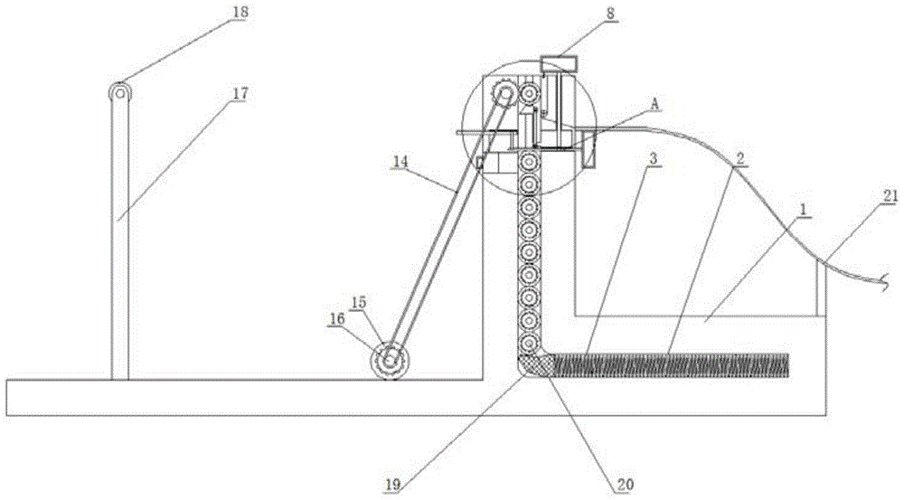
Fig. 1 is a three-dimensional structural view of a cloth collecting mechanism of a circular weaving machine provided by the utility model;
fig. 2 is a front view of a cloth collecting mechanism of a circular weaving machine according to the present invention;
fig. 3 is a structural plan view of a cloth collecting mechanism of the circular weaving machine provided by the present invention;
fig. 4 is an enlarged schematic view of a structure a of a cloth collecting mechanism of a circular weaving machine provided by the utility model.
In the figure: 1 base, 2 chambers, 3 springs, 4 pulling handles, 5 pushing rods, 6 driving rods, 7 meshing rods, 8 pressing handles, 9 sliding plates, 10 rollers, 11 driving gears, 12 pushing blocks, 13 partition plates, 14 belts, 15 motors, 16 guide frames, 17 rotating shaft frames, 18 rotating shafts, 19 soft rubber blocks and 20 driven gears.
Detailed Description
The technical solutions in the embodiments of the present invention will be described clearly and completely with reference to the accompanying drawings in the embodiments of the present invention, and it is obvious that the described embodiments are only some embodiments of the present invention, not all embodiments.
Referring to fig. 1-4, a cloth collecting mechanism of a circular weaving machine comprises a base 1, a cavity 2 is formed in the base 1, a rotating shaft frame 17 is fixedly installed on one side of the top of the base 1, a rotating shaft 18 is rotatably connected to the rotating shaft frame 17, a spring 3 is slidably connected to the inner wall of the cavity 2, a soft rubber block 19 is fixedly installed at one end of the spring 3, a switching mechanism is arranged on the inner wall of the base 1, a motor 15 is fixedly installed at the top of the base 1, a driving gear 11 is rotatably connected to one side of the base 1, the motor 15 is in transmission connection with the driving gear 11, a plurality of rollers 10 are slidably connected to the inner wall of the cavity 2, a driven gear 20 is fixedly installed on one side of each roller 10, the driven gear 20 is matched with the driving gear 11, and the plurality of rollers 10 are matched with the switching mechanism; the switching mechanism comprises a push rod 5, a driving rod 6, an engaging rod 7, a pressing handle 8, a sliding plate 9, a driving gear 11, a pushing block 12 and a partition plate 13, the push rod 5 is fixedly connected with a pulling handle 4, the push rod 5 is slidably connected with the inner wall of the chamber 2, one side of the push rod 5 is fixedly provided with a connecting rod, the top of one side of the connecting rod is fixedly connected with the partition plate 13, the partition plate 13 is slidably connected with the inner wall of the chamber 2, the top of the push rod 5 is rotatably connected with the driving rod 6, the top end of the driving rod 6 is rotatably connected with the pushing block 12, the inner wall of the chamber 2 is rotatably connected with the sliding plate 9, the inner wall of the chamber 2 is rotatably connected with the engaging rod 7, the engaging rod 7 is matched with the push rod 5, the top of the engaging rod 7 is fixedly provided with the pressing handle 8, the pressing handle 8 is matched with the sliding plate 9, and the partition plate 13, the push rod 5, the pushing block 12 and the sliding plate 9 are all matched with the roller 10, the pushing rod 5 is pulled by pulling the handle 4, the baffle 13 is pulled by the pushing rod 5, after the pushing rod 5 is separated from the first roller 10, the roller 10 is pushed upwards by the spring 3 and then contacts with the baffle 13, the pushing rod 5 can pull the pushing block 12 by the driving rod 6 to withdraw the pushing block 12, then the pushing rod 5 is inserted again, the pushing rod 5 is inserted between the first roller 10 and the second roller 10 and then withdraws the baffle 13, then the pushing rod 5 drives the pushing block 12 to be inserted into the bottom of the first roller 10 by the driving rod 6, the pushing rod 5 continuously enters, the pushing block 12 is lifted upwards through the chute, the pushing roller 10 is lifted upwards, the first roller 10 is separated from the second roller 10, when the rollers are lifted to the top, the rolling can be started by the driving of the motor 15, and the switching of the rollers 10 is realized; a rectangular groove is formed in the pushing rod 5 and is matched with the meshing rod 7, and the bottom end of the meshing rod 7 is in sliding contact with the inner wall of the rectangular groove, so that the meshing rod 7 can position the pushing rod 5; a positioning groove is formed in the sliding plate 9, an insertion rod is fixedly installed on one side of the bottom of the pulling handle 4, the insertion rod is matched with the positioning groove, the outer side of the insertion rod is in sliding contact with the inner wall of the positioning groove, and the sliding plate 9 can be fixed when the insertion rod is inserted into the insertion groove; one side of the base 1 is provided with a through hole, the inner wall of the through hole is connected with a roller door in a sliding manner, one side of the base 1 is fixedly provided with a guide frame 16 for receiving the rolled roller 10, the roller 10 can roll out along the guide frame 16, the terminal point of the guide frame 16 can be arranged at the position where the roller is required to be stacked, and the roller can be pushed in a manual manner without carrying; belt pulleys are fixedly mounted on one side of the driving gear 11 and an output shaft of the motor 15, and the two belt pulleys are sleeved with the same belt 14 and used for driving the driving gear 11, driving the gear 11 to drive the driven gear 20 to rotate, and driving the roller 10 by the driven gear 20; the top of soft glue piece 19 is the toper structure, and soft glue piece 19 cooperatees with the slurcam for when soft glue piece 19 promoted last cylinder 10, catch bar 5 will slide along the hypotenuse of soft glue piece 19 toper structure after inserting, separate last cylinder 10 and soft glue piece 19, just can not blocked by soft glue piece 19, is being close to the inclined plane of through-hole one side simultaneously, and when filling cylinder 10, first cylinder 10 will be pressed soft glue piece 19 down along the hypotenuse, conveniently fills cylinder 10.
In the utility model, when the steps woven by the circular weaving machine are required to be rolled, the roller 10 is required to be filled in the cavity 2 in advance, the material door is opened at one side of the base 1, the roller 10 is filled in the base 1 through the through hole, the roller 10 enters the inner wall of the base 1 to start the spring 3, before rolling, the push rod 5 is required to be pulled firstly, the push rod 5 slides to one side and pulls the clapboard 13 to move to one side, after the push rod 5 is separated from the first roller 10, the roller 10 is reset by the spring 3 to push upwards and then contacts with the clapboard 13, the push rod 5 can pull the push block 12 through the drive rod 6 while moving to one side, the push block 12 is withdrawn, then the push rod 5 is inserted again, the push rod 5 is inserted between the first roller 10 and the second roller 10, then the clapboard 13 is withdrawn, the cavity 2 is opened, then the push rod 5 drives the block 12 to be inserted into the bottom of the first roller 10 through the drive rod 6, the pushing rod 5 continues to enter, the pushing block 12 will rise upwards through the sliding chute, and the pushing roller 10 will rise upwards, at this time, the first roller 10 will be driven to separate from the second roller 10, the space between the two rollers 10 will be opened, when the roller is lifted to the top, the driven gear 20 at one side of the roller 10 will be meshed with the driving gear 11, at this time, the motor 15 will rotate to drive the driven gear 20 to rotate, the driven gear 20 will drive the roller 10 to rotate, the rolling will be started, the space between the first roller 10 and the second roller 10 will be opened, the rolling of the first roller 10 will not be affected, at the same time, the base 1 is also rotatably connected with the sliding plate 9, when the first roller 10 is lifted to the top, the sliding plate 9 can be rotated to the position where the sliding plate 9 is perpendicular to the base 1 for preventing the roller 10 from sliding out, the pressing handle 8 and the meshing rod 7 can be inserted, the inserting rod at one side of the bottom of the pressing handle 8 is inserted into the sliding plate 9, the sliding plate 9 is fixed, the bottom end of the engaging rod 7 can be inserted into the pushing rod 5, the pushing rod 5 is fixed, after winding is completed, the pressing handle 8 needs to be pressed first to bring the engaging rod 7 out, the sliding plate 9 and the pushing rod 5 are unlocked while the engaging rod is brought out, the sliding plate 9 is rotated to incline after unlocking, the sliding plate 9 can be connected with the guide frame 16 at the moment, the wound roller 10 is pulled to one side of the sliding plate 9, the roller 10 can roll out along the sliding plate 9 and the guide frame 16, the terminal point of the guide frame 16 can be arranged at a position where stacking is wanted, the sliding plate can be pushed in a manual mode without carrying, and the inserting and pushing rod 5 can be replaced by a new roller 10 by pulling the handle 4.
The above, only be the concrete implementation of the preferred embodiment of the present invention, but the protection scope of the present invention is not limited thereto, and any person skilled in the art is in the technical scope of the present invention, according to the technical solution of the present invention and the utility model, the concept of which is equivalent to replace or change, should be covered within the protection scope of the present invention.