CN214561618U - Dust-free splitting machine for wood board for furniture processing - Google Patents
Dust-free splitting machine for wood board for furniture processing Download PDFInfo
- Publication number
- CN214561618U CN214561618U CN202120333565.7U CN202120333565U CN214561618U CN 214561618 U CN214561618 U CN 214561618U CN 202120333565 U CN202120333565 U CN 202120333565U CN 214561618 U CN214561618 U CN 214561618U
- Authority
- CN
- China
- Prior art keywords
- dust
- cutting
- material blocking
- groove
- blocking box
- Prior art date
- Legal status (The legal status is an assumption and is not a legal conclusion. Google has not performed a legal analysis and makes no representation as to the accuracy of the status listed.)
- Active
Links
Images


Abstract
The utility model discloses a wood board dust-free dividing and cutting machine for furniture processing, which comprises a frame and a cutting table; a cutting knife is arranged on the cutting table; the cutting table is provided with a material blocking box in a sliding manner; the material blocking box is used for covering the cutting knife during cutting; the lower end of the material blocking box is open; the top of the material blocking box is provided with a dust hood; the dust hood is connected to the collector through a dust suction pipe; a filter plate is arranged in the collector; an exhaust fan is arranged on one side of the filter plate; through grooves are formed in two end faces of the material blocking box; a cutter groove extends upwards from the upper edge of the through groove; the cutter groove is used for allowing a cutter to pass through; the utility model discloses the technical scheme who takes has solved the problem of separation dust that current cutting machine can not be better when the cutting plank and the sweeps that splashes.
Description
Technical Field
The utility model relates to a furniture equipment processing technology field, concretely relates to dustless cutting machine of plank for furniture processing.
Background
The household equipment consists of four factors, namely materials, structures, appearance forms and functions, wherein the functions are leading and are power for promoting furniture development; the structure is a backbone and is the basis for realizing the functions. These four factors are interrelated and restrictive. Because the household equipment is designed and manufactured for meeting certain material requirements and use purposes of people, the household equipment also has factors in functions and appearance forms. The existing household equipment often uses a plate cutting machine in processing to cut raw materials such as wood plates and the like for forming structural appearance so as to meet the requirements of production and processing. A large amount of cutting saw-dusts and dust that can produce in the cutting process of plank stuff make the dust content in the workshop air increase in a large number, are unfavorable for the workman healthy, lack the dust removal mechanism that necessary facilitate the use on the current cutting bed, and dust removal mechanism generally is the suction hood of fixed setting in the cutting bed top, not only adjusts inconveniently, and does not have good effect to the separation dust and the saw-dust that splashes.
SUMMERY OF THE UTILITY MODEL
An object of the utility model is to provide a dustless cutting machine of plank for furniture processing solves the problem of separation dust that current cutting machine can not be better when cutting the plank and splash the sweeps.
In order to solve the technical problem, the utility model adopts the following technical scheme: a dust-free splitting machine for a wood board for furniture processing comprises a rack and a cutting table; a cutting knife is arranged on the cutting table; the cutting table is provided with a material blocking box in a sliding manner; the material blocking box is used for covering the cutting knife during cutting; the lower end of the material blocking box is open; the top of the material blocking box is provided with a dust hood; the dust hood is connected to the collector through a dust suction pipe; a filter plate is arranged in the collector; an exhaust fan is arranged on one side of the filter plate; through grooves are formed in two end faces of the material blocking box; a cutter groove extends upwards from the upper edge of the through groove; the cutter groove is used for allowing a cutter to pass through;
furthermore, the dust suction pipe comprises a first pipe section and a second pipe section; the first pipe section and the second pipe section are connected through an elbow piece; the first pipe section is positioned outside the material blocking box and connected with the collector; the second pipe section is connected with the dust hood; the first pipe section is a telescopic pipe;
furthermore, sliding convex edges are arranged on the edges of the two sides of the material blocking box; sliding rails are arranged on two sides of the cutting table corresponding to the sliding convex edges;
furthermore, a sliding plate is arranged on the end surface of the material blocking box; the sliding plate is used for blocking the through groove and the cutter groove during cutting;
furthermore, sliding ribs are arranged on the edges of the two sides of the sliding plate; sliding grooves extend upwards from the edges of the two sides of the through groove; the sliding ribs slide in the sliding grooves;
furthermore, a limit groove is arranged on the end surface of the material blocking box; a limiting strip is arranged on one side surface of the sliding plate close to the material blocking box and corresponds to the limiting groove;
furthermore, the lower edge of the sliding plate is provided with an installation groove; a roll shaft is rotationally arranged in the mounting groove;
a cutting groove is arranged on the cutting table corresponding to the cutting knife; the cutting knife is sleeved on the rotating shaft; one end of the rotating shaft is connected with a driving wheel; the transmission wheel is connected to the motor through a belt; a material receiving box is also arranged below the cutting groove.
Compared with the prior art, the beneficial effects of the utility model are one of following at least:
1. the material blocking box arranged on the cutting table in a sliding mode slides above the cutting knife during cutting, so that splashing scraps and dust generated by cutting can be blocked, the pollution to the surrounding environment can be reduced, and the convenience in use can be improved;
2. the lower end of the material blocking box is open, so that the material blocking box can slide on cutting and cover the cutting knife, a dust hood is arranged at the top of the material blocking box and is connected to the collector, and a certain negative pressure is generated by an exhaust fan in the collector, so that most of dust and waste scraps in the material blocking box can be sucked into the collector, and the cleanness of the cutting knife can be improved;
3. the filter plate arranged in the collector is beneficial to air passing and simultaneously avoids the influence of scraps and dust on the normal work of the exhaust fan, and the exhaust groove is also arranged on one side of the collector, which is close to the exhaust fan, and is beneficial to air passing;
4. set up logical groove on the both ends face of fender material box, be favorable to the plank to pass from the below of keeping off the material box when the cutting, be favorable to avoiding influencing the cutting, the cutter groove that the edge that leads to the groove upwards extends then is favorable to the cutting knife to pass through, is favorable to keeping off the material box and passes the cutting knife in a flexible way, is favorable to improving the convenience that keeps off the material box and use.
Drawings
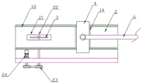
Fig. 1 is a front view structure diagram of the present invention.
Fig. 2 is a partial structural plan view of the present invention.
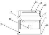
Fig. 3 is a schematic view of a material blocking box installation structure.
Fig. 4 is a schematic view of the sliding plate structure.
In the drawings: 1. a frame; 2. cutting table; 3. a cutting knife; 4. a material blocking box; 5. a dust hood; 6. a dust collection pipe; 61. a first tube section; 62. a second tube section; 7. a collector; 8. an exhaust fan; 9. a filter plate; 10. a through groove; 11. a cutter slot; 12. a sliding rib; 13. a slide rail; 14. a sliding plate; 15. sliding the ribs; 16. a chute; 17. a limiting groove; 18. a limiting strip; 19. mounting grooves; 20. a roll shaft; 21. cutting the groove; 22. a rotating shaft; 23. a driving wheel; 24. a motor; 25. a material receiving box.
Detailed Description
In order to make the objects, technical solutions and advantages of the present invention more clearly understood, the present invention is further described in detail below with reference to the accompanying drawings and embodiments. It should be understood that the specific embodiments described herein are merely illustrative of the invention and are not intended to limit the invention.
Example 1: as shown in fig. 1 to 4, a dust-free splitting machine for wood boards for furniture processing comprises a frame 1 and a cutting table 2; a cutting knife 3 is arranged on the cutting table 2; the cutting table 2 is provided with a material blocking box 4 in a sliding manner; the material blocking box 4 is used for covering the cutting knife 3 during cutting; the lower end of the material blocking box 4 is open; the top of the material blocking box 4 is provided with a dust hood 5; the dust hood 5 is connected to a collector 7 through a dust suction pipe 6; a filter plate 9 is arranged in the collector 7; an exhaust fan 8 is arranged on one side of the filter plate 9; through grooves 10 are formed in two end faces of the material blocking box 4; a cutter groove 11 extends upwards from the upper edge of the through groove 10; the cutter groove 11 is used for the cutter 3 to pass through; in the embodiment, the frame 1, the cutting table 2 and the cutting knife 3 are all conventional commercial products, and any reasonable structure, material and appropriate installation mode can be selected according to needs; in the embodiment, the material blocking box 4, the dust hood 5 and the dust collection pipe 6 are all made of conventional materials with certain mechanical strength, and any reasonable material and connection mode can be selected according to needs; in this embodiment, the collector 7 is made of a conventional material having a certain mechanical strength, and any reasonable material can be selected as required; in the embodiment, the exhaust fan 8 of the collector 7 adopts conventional commercial products, and any reasonable installation mode can be selected according to requirements; in this embodiment, the filter plate 9 is made of a conventional material with a certain mechanical strength, and any reasonable material and reasonable filter pore size can be selected according to the requirement; any reasonable collector 7 structure can be selected according to the requirement, so that proper negative pressure can be generated in the material blocking box 4; in this embodiment, the height and the width of the through groove 10 can be reasonably set as required. In this embodiment, the dust suction pipe 6 is further provided with a conventional check valve and a pressure gauge, which can be reasonably selected and arranged as required.
The material blocking box 4 arranged on the cutting table 2 in a sliding mode slides above the cutting knife 3 during cutting, so that splashing scraps and dust generated by cutting can be blocked, the pollution to the surrounding environment can be reduced, and the use convenience can be improved; the lower end of the material blocking box 4 is open, so that the material blocking box 4 can slide on cutting and cover the cutting knife 3, the top of the material blocking box 4 is provided with the dust hood 5, the dust hood 5 is connected to the collector 7, and certain negative pressure is generated through the exhaust fan 8 in the collector 7, so that most of dust and scraps in the material blocking box 4 can be sucked into the collector 7, and the cleanness of the cutting knife 3 can be improved; the filter plate 9 arranged in the collector 7 is beneficial to air passing and simultaneously avoids the influence of scraps and dust on the normal work of the exhaust fan 8, and the exhaust groove is also arranged on one side of the collector 7 close to the exhaust fan 8 and is beneficial to air passing; offer logical groove 10 on keeping off the both ends face of material box 4, be favorable to the plank to pass from the below of keeping off material box 4 when the cutting, be favorable to avoiding influencing the cutting, the cutter groove 11 that leads to the edge of groove 10 and upwards extends then is favorable to cutting knife 3 to pass through, is favorable to keeping off material box 4 and passes cutting knife 3 in a flexible way, is favorable to improving the convenience that keeps off material box 4 used.
The dust suction pipe 6 comprises a first pipe section 61 and a second pipe section 62; the first pipe section 61 and the second pipe section 62 are connected through an elbow piece; the first pipe section 61 is positioned outside the material blocking box 4 and is connected with the collector 7; the second pipe section is connected with the dust hood 5; the first pipe section 61 is a telescopic pipe; in the embodiment, the elbow piece is made of conventional commercially available products, and any reasonable structure and connection mode can be selected according to needs; in this embodiment, the first pipe section 61 is made of a conventional telescopic pipe material with a certain mechanical strength, and any reasonable material, structure and connection mode can be selected according to needs; in this embodiment, the second pipe section 62 is made of a conventional pipe material with a certain mechanical strength, and any reasonable material, structure and connection mode can be selected according to the requirement; a first pipe section 61 outside the material blocking box 4 is arranged into a telescopic pipe structure; when the material blocking box 4 slides on the cutting table 2, the length of the first pipe section 61 is adjusted accordingly, and the flexibility and the stability of the structure are improved.
The edges of two sides of the material blocking box 4 are provided with sliding convex edges 12; sliding rails 13 are arranged on two sides of the cutting table 2 corresponding to the sliding convex edges 12; in this embodiment, the sliding protruding rib 12 is made of a conventional material with a certain mechanical strength, and any reasonable material and a fixed connection mode with the material blocking box 4 can be selected according to needs; sliding protruding edge 12 and slide rail 13 all adopt conventional adaptation structure, be favorable to keeping off magazine 4 to slide on cutting table 2 can, through sliding protruding edge 12 and slide rail 13, be favorable to improving the gliding stability and the flexibility of keeping off magazine 4 on cutting table 2.
A sliding plate 14 is arranged on the end surface of the material blocking box 4; the sliding plate 14 is used for blocking the through groove 10 and the cutter groove 11 during cutting; in this embodiment, the sliding plate 14 is made of a conventional material having a certain mechanical strength, and any reasonable material can be selected according to the requirement; the sliding plate 14 is beneficial to blocking the through groove 10 and the cutter groove 11 during cutting, and the sliding plate 14 naturally falls on the upper surface of the wood board due to self weight, so that the influence on the cutting template is reduced while dust and splashed scraps are favorably blocked.
The edges of two sides of the sliding plate 14 are provided with sliding ribs 15; the edges of the two sides of the through groove 10 extend upwards to form sliding grooves 16; the sliding ribs 15 slide in the sliding grooves 16; in this embodiment, the sliding ribs 15 are made of conventional materials with certain mechanical strength, and any reasonable material and fixed connection mode with the sliding plate 14 can be selected according to requirements; in this embodiment, slide in spout 16 through slip rib 15, be favorable to realizing that sliding plate 14 slides from top to bottom at the terminal surface that keeps off material box 4, be favorable to promoting sliding plate 14 to suitable high messenger's template as required and pass through, be favorable to blocking logical groove 10 and the cutter groove 11 that keeps off material box 4 terminal surface simultaneously, be favorable to avoiding influencing the cutting and go on when being favorable to improving the cleaning of keeping off material box 4.
A limit groove 17 is arranged on the end surface of the material blocking box 4; the surface of one side of the sliding plate 14, which is close to the material blocking box 4, is provided with a limiting strip 18 corresponding to the limiting groove 17; in the embodiment, the limiting groove 17 and the limiting strip 18 arranged on the end surface of the material blocking box 4 are clamped, when the position of the material blocking plate is adjusted in a sliding mode without cutting, the material blocking plate is completely lifted to the limiting strip 18 and clamped in the limiting groove 17, so that the cutter grooves 11 of the through grooves 10 on the two end surfaces of the material blocking box 4 are completely exposed, the passing of the cutting knife 3 is facilitated, and the stability and the flexibility of the structure are improved; in this embodiment, the position setting of the limiting groove 17 and the limiting strip 18 is suitable.
The lower edge of the sliding plate 14 is provided with a mounting groove 19; a roll shaft 20 is rotatably arranged in the mounting groove 19; in this embodiment, the roll shaft 20 is made of a conventional material having a certain mechanical strength, and any reasonable material can be selected as required; in this embodiment, the roller shaft 20 penetrates through the fixing rod, the roller shaft 20 is movably sleeved on the fixing rod, and two ends of the fixing rod are fixed on the inner walls of two sides of the mounting groove 19, so that the roller shaft 20 can flexibly rotate on the lower edge of the sliding plate 14; any reasonable structure and installation mode of the roll shaft 20 can be selected according to the requirement; the mounting groove 19 is beneficial to mounting the roller shaft 20, the roller shaft 20 protrudes from the lower edge of the sliding plate 14, when the wood plate is pushed out from the two ends of the material blocking box 4 during cutting, the roller shaft 20 is beneficial to reducing resistance to the surface of the wood plate and is beneficial to moving the wood plate, meanwhile, the sealing performance of the joint of the upper surface of the wood plate and the lower edge of the sliding plate 14 is beneficial to improving, and the passing of waste scraps and dust is facilitated.
A cutting groove 21 is formed in the cutting table 2 corresponding to the cutting knife 3; the cutting knife 3 is sleeved on the rotating shaft 22; one end of the rotating shaft 22 is connected with a driving wheel 23; the transmission wheel 23 is connected to a motor 24 through a belt; a material receiving box 25 is also arranged below the cutting groove 21; in this embodiment, the cutting groove 21 facilitates the cutting knife 3 to protrude out of the surface of the cutting table 2 and the wood board; in the embodiment, the rotating shaft 22, the driving wheel 23, the motor 24 and the belt are all conventional commercial products, and any reasonable structure and installation mode can be selected according to needs; after an output shaft of the motor 24 is connected with the transmission wheel 23 through a belt pulley, the motor 24 is started to drive the transmission wheel 23 to rotate, so that the rotating shaft 22 is driven to rotate, the rotating shaft 22 drives the cutting knife 3 to rotate, the cutting is facilitated, and any driving mode in other modes can be selected according to requirements; in this embodiment, the receiving groove is beneficial to receiving the scraps falling from the cutting groove 21; the material receiving groove adopts any reasonable structure and material.
Although the invention has been described herein with reference to a number of illustrative embodiments thereof, it should be understood that numerous other modifications and embodiments can be devised by those skilled in the art that will fall within the spirit and scope of the principles of this invention. More specifically, various variations and modifications are possible in the component parts and/or arrangements of the subject combination arrangement within the scope of the disclosure, the drawings and the appended claims. In addition to variations and modifications in the component parts and/or arrangements, other uses will also be apparent to those skilled in the art.
Claims (8)
1. A dust-free splitting machine for a wood board for furniture processing comprises a rack (1) and a cutting table (2); a cutting knife (3) is arranged on the cutting table (2); the method is characterized in that: the cutting table (2) is provided with a material blocking box (4) in a sliding manner; the material blocking box (4) is used for covering the cutting knife (3) during cutting; the lower end of the material blocking box (4) is open; the top of the material blocking box (4) is provided with a dust hood (5); the dust hood (5) is connected to the collector (7) through a dust suction pipe (6); a filter plate (9) is arranged in the collector (7); an exhaust fan (8) is arranged on one side of the filter plate (9); through grooves (10) are formed in two end faces of the material blocking box (4); a cutter groove (11) extends upwards from the upper edge of the through groove (10); the cutter groove (11) is used for allowing the cutter (3) to pass through.
2. The dust-free splitting machine for the wood board for furniture processing according to claim 1, wherein: the dust suction pipe (6) comprises a first pipe section (61) and a second pipe section (62); the first pipe section (61) and the second pipe section (62) are connected through an elbow piece; the first pipe section (61) is positioned outside the material blocking box (4) and is connected with the collector (7); the second pipe section (62) is connected with the dust hood (5); the first pipe section (61) is a telescopic pipe.
3. The dust-free splitting machine for the wood board for furniture processing according to claim 1, wherein: the edges of two sides of the material blocking box (4) are provided with sliding convex edges (12); sliding rails (13) are arranged on two sides of the cutting table (2) corresponding to the sliding convex ribs (12).
4. The dust-free splitting machine for the wood board for furniture processing according to claim 1, wherein: a sliding plate (14) is arranged on the end surface of the material blocking box (4); the sliding plate (14) is used for blocking the through groove (10) and the cutter groove (11) during cutting.
5. The dust-free splitting machine for the wood board for furniture processing as claimed in claim 4, wherein: the edges of two sides of the sliding plate (14) are provided with sliding ribs (15); the edges of two sides of the through groove (10) extend upwards to form sliding grooves (16); the sliding ribs (15) slide in the sliding grooves (16).
6. The dust-free splitting machine for the wood board for furniture processing as claimed in claim 4, wherein: a limiting groove (17) is arranged on the end surface of the material blocking box (4); and a limiting strip (18) is arranged on the surface of one side, close to the material blocking box (4), of the sliding plate (14) and corresponds to the limiting groove (17).
7. The dust-free splitting machine for the wood board for furniture processing as claimed in claim 4, wherein: the lower edge of the sliding plate (14) is provided with a mounting groove (19); and a roll shaft (20) is rotationally arranged in the mounting groove (19).
8. The dust-free splitting machine for the wood board for furniture processing according to claim 1, wherein: a cutting groove (21) is arranged on the cutting table (2) corresponding to the cutting knife (3); the cutting knife (3) is sleeved on the rotating shaft (22); one end of the rotating shaft (22) is connected with a driving wheel (23); the transmission wheel (23) is connected to a motor (24) through a belt; a material receiving box (25) is also arranged below the cutting groove (21).
Priority Applications (1)
| Application Number | Priority Date | Filing Date | Title |
|---|---|---|---|
| CN202120333565.7U CN214561618U (en) | 2021-02-05 | 2021-02-05 | Dust-free splitting machine for wood board for furniture processing |
Applications Claiming Priority (1)
| Application Number | Priority Date | Filing Date | Title |
|---|---|---|---|
| CN202120333565.7U CN214561618U (en) | 2021-02-05 | 2021-02-05 | Dust-free splitting machine for wood board for furniture processing |
Publications (1)
| Publication Number | Publication Date |
|---|---|
| CN214561618U true CN214561618U (en) | 2021-11-02 |
Family
ID=78315824
Family Applications (1)
| Application Number | Title | Priority Date | Filing Date |
|---|---|---|---|
| CN202120333565.7U Active CN214561618U (en) | 2021-02-05 | 2021-02-05 | Dust-free splitting machine for wood board for furniture processing |
Country Status (1)
| Country | Link |
|---|---|
| CN (1) | CN214561618U (en) |
-
2021
- 2021-02-05 CN CN202120333565.7U patent/CN214561618U/en active Active
Similar Documents
| Publication | Publication Date | Title |
|---|---|---|
| CN215511417U (en) | Sawing machine for manufacturing wood board | |
| CN214561618U (en) | Dust-free splitting machine for wood board for furniture processing | |
| CN208543584U (en) | A kind of full-automatic timber finger joint machine | |
| CN208714169U (en) | A kind of multifunction automatic cutting machine | |
| CN216600256U (en) | Automatic vertical beveler is used in production of multilayer circuit board of business turn over material | |
| CN220499419U (en) | Furniture planing machine | |
| CN215749726U (en) | Dust collector between furniture processing vehicle | |
| CN213055205U (en) | Bamboo wood fiber board cutting workbench | |
| CN110919782A (en) | High-efficient splitting equipment is used in processing of fire-retardant plank | |
| CN213829346U (en) | Avoid plank cutting machine of plank fracture | |
| CN218614288U (en) | Cutting device for producing composite board | |
| CN214136443U (en) | Wood chip collecting device of wood carving machine | |
| CN220179591U (en) | Piece processing apparatus is used in timber processing | |
| CN213946762U (en) | A multi-functional router for furniture board processing | |
| CN219380893U (en) | Wooden furniture bead cutter that possesses dust absorption function | |
| CN220008139U (en) | Cutting machine with dust removal function | |
| CN218802873U (en) | Environment-friendly plank cutting machine | |
| CN216328888U (en) | Corner cutting mechanism for bakelite plate processing | |
| CN220741329U (en) | A paper cutting and leveling device | |
| CN212266119U (en) | Timber reducing mechanism is used in furniture production | |
| CN220030361U (en) | Slitting device for paperboard laminating process | |
| CN211867938U (en) | Production of pp cavity board is with automatic dust removal structure of fluting | |
| CN216099137U (en) | PVC board production is with extrusion device that has garbage collection mechanism | |
| CN211030339U (en) | Elevator packing box panel processingequipment | |
| CN209887747U (en) | Plate cutting device |
Legal Events
| Date | Code | Title | Description |
|---|---|---|---|
| GR01 | Patent grant | ||
| GR01 | Patent grant |