CN214553237U - Convenient mixer front end plate composite set who dismantles - Google Patents
Convenient mixer front end plate composite set who dismantles Download PDFInfo
- Publication number
- CN214553237U CN214553237U CN202120650033.6U CN202120650033U CN214553237U CN 214553237 U CN214553237 U CN 214553237U CN 202120650033 U CN202120650033 U CN 202120650033U CN 214553237 U CN214553237 U CN 214553237U
- Authority
- CN
- China
- Prior art keywords
- end plate
- clamping
- screw hole
- groove
- picture peg
- Prior art date
- Legal status (The legal status is an assumption and is not a legal conclusion. Google has not performed a legal analysis and makes no representation as to the accuracy of the status listed.)
- Active
Links
- 239000002131 composite material Substances 0.000 title claims abstract description 7
- 239000000463 material Substances 0.000 claims description 3
- 238000012423 maintenance Methods 0.000 abstract description 4
- 239000004576 sand Substances 0.000 abstract 4
- 210000003141 lower extremity Anatomy 0.000 abstract 1
- 238000003756 stirring Methods 0.000 description 14
- 230000000694 effects Effects 0.000 description 4
- 238000004140 cleaning Methods 0.000 description 3
- 238000000034 method Methods 0.000 description 2
- 230000004075 alteration Effects 0.000 description 1
- 230000009286 beneficial effect Effects 0.000 description 1
- 238000009434 installation Methods 0.000 description 1
- 238000012986 modification Methods 0.000 description 1
- 230000004048 modification Effects 0.000 description 1
- 238000007789 sealing Methods 0.000 description 1
- 238000006467 substitution reaction Methods 0.000 description 1
Images


Landscapes
- Floor Finish (AREA)
Abstract
The utility model discloses a convenient mixer front end plate composite set who dismantles, including front end plate, picture peg and crossbeam, first sand grip is installed to the top intermediate position of front end plate, and the top of first sand grip is connected with the locating plate, first screw has been seted up on the surface of locating plate, first draw-in groove has all been seted up to the left and right sides of first sand grip, and the top of first draw-in groove is provided with the side edge, the internal surface fixing on side edge has the second sand grip, the second screw has all been seted up to the top left and right sides of front end plate, the picture peg is settled in the top of locating plate, and the lower limb of picture peg has seted up first card way, the crossbeam is installed in the top of picture peg, and the fourth screw has all been seted up to the left and right sides of crossbeam. This mixer front end plate composite set sets up the (mixing) shaft bearing frame and can block and fix between first draw-in groove and second draw-in groove, and then makes the later stage dismantle the picture peg and just can dismantle the (mixing) shaft, the dismantlement maintenance and the clean operation of the (mixing) shaft of being convenient for.
Description
Technical Field
The utility model relates to a mixer technical field specifically is a convenient mixer front end plate composite set who dismantles.
Background
The mixer is a mechanical equipment commonly used, divide into domestic and industrial use, and the mainly used stirs the material for the material mixes more fully, and the barrel of general mixer is mostly the integrated into one piece structure, and the (mixing) shaft dress is in the inside of mixer barrel. However, such a mounting structure is inconvenient to detach the stirring shaft in the using process, which causes inconvenience in later maintenance and cleaning operations, and for this reason, a mixer front end plate combination device convenient to detach is provided.
SUMMERY OF THE UTILITY MODEL
An object of the utility model is to provide a convenient mixer front end plate composite set who dismantles to the barrel of solving the general mixer that proposes in the above-mentioned background art is mostly the integrated into one piece structure, and the (mixing) shaft dress is in the inside of stirring barrel. However, such a mounting structure is inconvenient to disassemble the stirring shaft during use, resulting in inconvenient maintenance and cleaning operations at a later stage.
In order to achieve the above object, the utility model provides a following technical scheme: a convenient mixer front end plate combination device of dismantling comprises a front end plate, a plug plate and a cross beam, wherein a first convex strip is installed at the middle position above the front end plate, a positioning plate is connected above the first convex strip, a first screw hole is formed in the surface of the positioning plate, first clamping grooves are formed in the left side and the right side of the first convex strip, a side edge is arranged above the first clamping groove, a second convex strip is fixed on the inner surface of the side edge, second screw holes are formed in the left side and the right side of the upper side of the front end plate, the plug plate is arranged above the positioning plate, a first clamping channel is formed in the lower edge of the plug plate, a third screw hole is formed in the lower position of the middle part of the plug plate, second clamping channels are formed in the left side surface and the right side surface of the plug plate, the cross beam is installed at the top of the plug plate, fourth screw holes are formed in the left side and the right side of the cross beam, and second clamping grooves are formed in the lower left corner and the right corner of the plug plate, and the inner surfaces of the second clamping groove and the first clamping groove are provided with anti-slip pads, and the connecting part of the plugboard and the positioning board is provided with a slot.
Preferably, the first protruding strip is matched with the first clamping channel in size, and the first protruding strip and the first clamping channel are matched with each other to form a clamping structure.
Preferably, the first clamping groove and the second clamping groove are both arc-shaped structures, and the first clamping groove and the second clamping groove are spliced with each other to form a circular structure.
Preferably, the second protruding strip is matched with the second clamping channel in size, and the second protruding strip and the second clamping channel are matched with each other to form a clamping structure.
Preferably, the fourth screw hole, the second screw hole, the third screw hole and the first screw hole are identical in size, and meanwhile the positioning plate and the plug board form a clamping structure through the slot.
Preferably, the non-slip mat is made of rubber, and the thickness of the non-slip mat is equal to that of the front end plate and the plug plate.
Compared with the prior art, the beneficial effects of the utility model are that:
1. the conveniently-disassembled mixer front end plate combination device is provided with a first raised line and a second raised line, wherein the width of the first raised line and the width of the second raised line are half of the thickness of a front end plate, the width of the first clamping channel and the width of the second clamping channel are half of the thickness of an inserting plate, and the protruding distance of the first raised line and the second raised line is equal to the depth of the first clamping channel and the depth of the second clamping channel, so that the first raised line and the second raised line can be respectively clamped and embedded in the first clamping channel and the second clamping channel, and the joint of the middle part of the connection of the front end plate and the inserting plate is more tightly attached;
2. the positions of the first clamping groove and the second clamping groove are used for arranging the stirring shaft bearing seat, so that the stirring shaft bearing seat can be clamped between the first clamping groove and the second clamping groove for fixing, the stirring shaft can be disassembled by disassembling the inserting plate at the later stage, the use is more convenient and faster, the disassembling, the maintenance and the cleaning operation of the stirring shaft are convenient, and the anti-slip mat is arranged to be tightly attached to the stirring shaft bearing seat, so that the sealing effect can be improved, and the problem of slipping can be effectively prevented;
3. set up the fourth screw, the second screw, the size of four screws of third screw and first screw equals, and the fourth screw is adjusted well with the second screw, and the third screw is adjusted well with first screw, conveniently just can fix front end plate and picture peg through twisting four group of the same kind of screws, the simple operation, and labour saving and time saving, and utilize the block effect between locating plate and the slot, can fix a position fast the connection operation between front end plate and the picture peg, reduce the possibility of dislocation.
Drawings
FIG. 1 is a schematic perspective view of the present invention;
FIG. 2 is a schematic front view of the present invention;
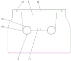
fig. 3 is the utility model discloses front end plate and picture peg concatenation installation orthographic view structure schematic.
In the figure: 1. a front end plate; 2. a first rib; 3. positioning a plate; 4. a first screw hole; 5. a first card slot; 6. a side edge; 7. a second convex strip; 8. a second screw hole; 9. inserting plates; 10. a first card channel; 11. a third screw hole; 12. a second card channel; 13. a cross beam; 14. a fourth screw hole; 15. a second card slot; 16. a non-slip mat; 17. and (4) a slot.
Detailed Description
The technical solutions in the embodiments of the present invention will be described clearly and completely with reference to the accompanying drawings in the embodiments of the present invention, and it is obvious that the described embodiments are only some embodiments of the present invention, not all embodiments. Based on the embodiments in the present invention, all other embodiments obtained by a person skilled in the art without creative work belong to the protection scope of the present invention.
Referring to fig. 1-3, the present invention provides a technical solution: a mixer front end plate combination device convenient to disassemble comprises a front end plate 1, a first convex strip 2, a positioning plate 3, a first screw hole 4, a first clamping groove 5, a side edge 6, a second convex strip 7, a second screw hole 8, an inserting plate 9, a first clamping channel 10, a third screw hole 11, a second clamping channel 12, a cross beam 13, a fourth screw hole 14, a second clamping groove 15, an anti-slip pad 16 and a slot 17, wherein the first convex strip 2 is installed at the middle position above the front end plate 1, the positioning plate 3 is connected above the first convex strip 2, the first screw hole 4 is formed in the surface of the positioning plate 3, the first clamping groove 5 is formed in each of the left side and the right side of the first convex strip 2, the side edge 6 is arranged above the first clamping groove 5, the second convex strip 7 is fixed on the inner surface of the side edge 6, the second screw hole 8 is formed in each of the left side and the right side above the front end plate 1, the inserting plate 9 is arranged above the positioning plate 3, and the first clamping channel 10 is formed in the lower edge of the inserting plate 9, a third screw hole 11 is formed in the lower position of the middle of the inserting plate 9, second clamping channels 12 are formed in the left side surface and the right side surface of the inserting plate 9, the cross beam 13 is installed at the top of the inserting plate 9, fourth screw holes 14 are formed in the left side surface and the right side surface of the cross beam 13, second clamping grooves 15 are formed in the left lower corner and the right lower corner of the inserting plate 9, anti-skid pads 16 are installed on the inner surfaces of the second clamping grooves 15 and the first clamping grooves 5, and a slot 17 is formed in the connecting position of the inserting plate 9 and the positioning plate 3;
the first convex strip 2 is matched with the first clamping channel 10 in size, the first convex strip 2 is matched with the first clamping channel 10 to form a clamping structure, the second convex strip 7 is matched with the second clamping channel 12 in size, the second convex strip 7 is matched with the second clamping channel 12 to form a clamping structure, the width of the first convex strip 2 and the width of the second convex strip 7 are half of the thickness of the front end plate 1, the width of the inner hole grooves of the first clamping channel 10 and the second clamping channel 12 is half of the thickness of the plug board 9, meanwhile, the protruding distance of the first convex strip 2 and the second convex strip 7 is equal to the depth of the inner hole grooves of the first clamping channel 10 and the second clamping channel 12, the first convex strip 2 and the second convex strip 7 can be respectively clamped inside the first clamping channel 10 and the second clamping channel 12, further, the joint of the middle connecting part of the front end plate 1 and the plug board 9 is more tightly attached, and the appearance structures of the first clamping channel 5 and the second clamping channel 15 are both arc structures, the first clamping groove 5 and the second clamping groove 15 are mutually spliced to form a circular structure, and the positions of the first clamping groove 5 and the second clamping groove 15 are used for arranging a stirring shaft bearing seat, so that the stirring shaft bearing seat can be clamped between the first clamping groove 5 and the second clamping groove 15 for fixing, and further the stirring shaft can be disassembled by disassembling the inserting plate 9 at the later stage, so that the stirring shaft is more convenient and faster to use and is convenient to disassemble, maintain and clean the stirring shaft;
the sizes of the fourth screw hole 14, the second screw hole 8 and the third screw hole 11 are identical with those of the first screw hole 4, meanwhile, the positioning plate 3 forms a clamping structure with the plug board 9 through the slot 17, the four screw holes of the fourth screw hole 14, the second screw hole 8 and the third screw hole 11 are equal with those of the first screw hole 4, the fourth screw hole 14 is aligned with the second screw hole 8, the third screw hole 11 is aligned with the first screw hole 4, the front end plate 1 and the plug board 9 can be conveniently fixed by screwing four groups of screws of the same kind, the operation is convenient, time and labor are saved, the connection operation between the front end plate 1 and the plug board 9 can be quickly positioned by utilizing the clamping effect between the positioning plate 3 and the slot 17, the possibility of dislocation is reduced, the non-slip mat 16 is made of rubber, the thickness of the non-slip mat 16 is equal to that of the front end plate 1 and the plug board 9, the non-slip mat 16 can be tightly attached to the bearing seat, not only can improve sealed effect, can also effectively prevent the problem of skidding.
The working principle is as follows: for the mixer front end plate combination device convenient to disassemble, firstly, the front end plate 1 is placed on a flat table top, then the mixer shaft bearing seat is firstly placed in the first clamping groove 5, the mixer shaft bearing seat is contacted with the anti-skid pad 16, then the cross beam 13 is held to drive the inserting plate 9 to move, so that the positions between the positioning plate 3 and the inserting groove 17 are aligned, the inserting plate 9 is downwards inserted and placed towards the middle part of the front end plate 1 along the side edge 6, so that the positioning plate 3 is clamped into the inserting groove 17, meanwhile, the first convex strip 2 is clamped into the first clamping channel 10, the second convex strip 7 is clamped into the second clamping channel 12 until the inserting plate 9 is completely clamped on the front end plate 1, at the moment, the upper surface of the cross beam 13 is flush with the upper surface of the front end plate 1, the positions between the fourth screw hole 14 and the second screw hole 8 are coincident, the positions between the third screw hole 11 and the first screw hole 4 are coincident, and the second clamping groove 15 and the anti-skid pad 16 are clamped above the mixer shaft bearing seat, then, bolts are screwed between the fourth screw hole 14 and the second screw hole 8 and between the third screw hole 11 and the first screw hole 4 in sequence, and the inserting plate 9 and the front end plate 1 are fixed for the second time through the bolts, so that the using process of the whole mixer front end plate combination device convenient to disassemble is completed.
Although embodiments of the present invention have been shown and described, it will be appreciated by those skilled in the art that changes, modifications, substitutions and alterations can be made in these embodiments without departing from the principles and spirit of the invention, the scope of which is defined in the appended claims and their equivalents.
Claims (6)
1. The utility model provides a convenient mixer front end plate composite set who dismantles, includes front end plate (1), picture peg (9) and crossbeam (13), its characterized in that: the improved structure of the plug board is characterized in that a first convex strip (2) is installed at the middle position above the front end plate (1), a positioning plate (3) is connected above the first convex strip (2), a first screw hole (4) is formed in the surface of the positioning plate (3), first clamping grooves (5) are formed in the left side and the right side of the first convex strip (2), a side edge (6) is arranged above the first clamping groove (5), a second convex strip (7) is fixed on the inner surface of the side edge (6), second screw holes (8) are formed in the left side and the right side of the upper portion of the front end plate (1), the plug board (9) is arranged above the positioning plate (3), a first clamping channel (10) is formed in the lower edge of the plug board (9), a third screw hole (11) is formed in the position below the middle portion of the plug board (9), second clamping channels (12) are formed in the left side and the right side of the plug board (9), and a crossbeam (13) is installed at the top of the plug board (9), and fourth screw (14) have all been seted up to the left and right sides of crossbeam (13), second draw-in groove (15) have all been seted up to the lower left corner and the lower right corner of picture peg (9), and the internal surface of second draw-in groove (15) and first draw-in groove (5) all installs slipmat (16), slot (17) have been seted up with the junction of locating plate (3) in picture peg (9).
2. The mixer front end plate assembly with convenient disassembly of claim 1, wherein: the first raised strip (2) is matched with the first clamping channel (10) in size, and the first raised strip (2) and the first clamping channel (10) are matched with each other to form a clamping structure.
3. The mixer front end plate assembly with convenient disassembly of claim 1, wherein: the first clamping groove (5) and the second clamping groove (15) are both arc-shaped in shape, and the first clamping groove (5) and the second clamping groove (15) are spliced with each other to form a circular structure.
4. The mixer front end plate assembly with convenient disassembly of claim 1, wherein: the second raised strip (7) is matched with the second clamping channel (12) in size, and the second raised strip (7) and the second clamping channel (12) are matched with each other to form a clamping structure.
5. The mixer front end plate assembly with convenient disassembly of claim 1, wherein: the fourth screw hole (14), the second screw hole (8), the third screw hole (11) and the first screw hole (4) are identical in size, and meanwhile, the positioning plate (3) and the plug board (9) form a clamping structure through the slot (17).
6. The mixer front end plate assembly with convenient disassembly of claim 1, wherein: the material of slipmat (16) is rubber, and the thickness of slipmat (16) equals with the thickness homoenergetic of front end board (1) and picture peg (9).
Priority Applications (1)
| Application Number | Priority Date | Filing Date | Title |
|---|---|---|---|
| CN202120650033.6U CN214553237U (en) | 2021-03-31 | 2021-03-31 | Convenient mixer front end plate composite set who dismantles |
Applications Claiming Priority (1)
| Application Number | Priority Date | Filing Date | Title |
|---|---|---|---|
| CN202120650033.6U CN214553237U (en) | 2021-03-31 | 2021-03-31 | Convenient mixer front end plate composite set who dismantles |
Publications (1)
| Publication Number | Publication Date |
|---|---|
| CN214553237U true CN214553237U (en) | 2021-11-02 |
Family
ID=78322534
Family Applications (1)
| Application Number | Title | Priority Date | Filing Date |
|---|---|---|---|
| CN202120650033.6U Active CN214553237U (en) | 2021-03-31 | 2021-03-31 | Convenient mixer front end plate composite set who dismantles |
Country Status (1)
| Country | Link |
|---|---|
| CN (1) | CN214553237U (en) |
-
2021
- 2021-03-31 CN CN202120650033.6U patent/CN214553237U/en active Active
Similar Documents
| Publication | Publication Date | Title |
|---|---|---|
| CN208168363U (en) | A kind of device preventing concrete column mould bottom spillage | |
| CN210105283U (en) | Composite material template convenient to assemble | |
| CN204677555U (en) | Assembly fixing component | |
| CN209585412U (en) | A steel corrugated plate structure for easy fixing and dismantling | |
| CN217633671U (en) | Detachable efficient chain | |
| CN213174618U (en) | Large-scale ground parquet stone | |
| CN212351770U (en) | A kind of clamp for quick disassembly and assembly of on-line monitor | |
| CN210397336U (en) | Glass fiber board mounting structure | |
| CN221694922U (en) | Positioning device for punching of aluminum die plate | |
| CN223986506U (en) | A quick-release integrated frame structure for switches | |
| CN224119855U (en) | Easy-to-mount and dismount modularized floor | |
| CN203258836U (en) | Mounting bracket based on central air conditioner outer machine | |
| CN220644780U (en) | Waterproof aluminum veneer | |
| CN216428884U (en) | Reverse-beating decorative plate anchoring structure | |
| CN219600010U (en) | Device for realizing consistency of splicing gaps during processing of ceramic tile wall plates | |
| CN218397231U (en) | Operating device | |
| CN207026249U (en) | Rush elongated hole die craft equipment on special-shaped angle steel | |
| CN218714675U (en) | Detachable anti-static floor splicing and mounting bracket | |
| CN220909096U (en) | Building templates convenient to cyclic utilization | |
| CN204992463U (en) | Flange mounting structure and use this mounting structure's cable installing support | |
| CN222482657U (en) | Multichannel radiating desktop | |
| CN222506717U (en) | LED backlight panel structure | |
| CN218234318U (en) | Building steel form convenient to installation is dismantled | |
| CN210762147U (en) | A new type of special ferrule for fasteners | |
| CN205713107U (en) | A kind of environmental protection steel wood a tree, used in making timber for boats |
Legal Events
| Date | Code | Title | Description |
|---|---|---|---|
| GR01 | Patent grant | ||
| GR01 | Patent grant |