CN214553044U - A wall-mounted electric mixer - Google Patents

A wall-mounted electric mixer Download PDF

Info

Publication number
CN214553044U
CN214553044U CN202120320102.7U CN202120320102U CN214553044U CN 214553044 U CN214553044 U CN 214553044U CN 202120320102 U CN202120320102 U CN 202120320102U CN 214553044 U CN214553044 U CN 214553044U
Authority
CN
China
Prior art keywords
mounting
fixedly connected
column
rotating column
rod
Prior art date
Legal status (The legal status is an assumption and is not a legal conclusion. Google has not performed a legal analysis and makes no representation as to the accuracy of the status listed.)
Active
Application number
CN202120320102.7U
Other languages
Chinese (zh)
Inventor
郭尊波
谭利花
吕金香
胡文建
张建霞
Current Assignee (The listed assignees may be inaccurate. Google has not performed a legal analysis and makes no representation or warranty as to the accuracy of the list.)
Shandong Yuanzheng Testing Technology Co ltd
Original Assignee
Shandong Yuanzheng Testing Technology Co ltd
Priority date (The priority date is an assumption and is not a legal conclusion. Google has not performed a legal analysis and makes no representation as to the accuracy of the date listed.)
Filing date
Publication date
Application filed by Shandong Yuanzheng Testing Technology Co ltd filed Critical Shandong Yuanzheng Testing Technology Co ltd
Priority to CN202120320102.7U priority Critical patent/CN214553044U/en
Application granted granted Critical
Publication of CN214553044U publication Critical patent/CN214553044U/en
Active legal-status Critical Current
Anticipated expiration legal-status Critical

Links

Images

Landscapes

  • Mixers Of The Rotary Stirring Type (AREA)
  • Food-Manufacturing Devices (AREA)

Abstract

本实用新型公开了一种防挂壁的电动搅拌机,涉及搅拌机技术领域,包括安装壳,所述安装壳底部两侧固定连接安装腿,所述安装壳内设置转动柱,转动柱上方的安装壳内顶壁转动连接安装筒,所述转动柱顶端延伸至转动柱内,且与安装筒上下滑动连接,所述转动柱下端开设通槽,通槽下方的安装壳内底部固定连接限位柱,限位柱延伸至通槽内,且与转动柱活动接触,所述转动柱上固定连接搅拌杆,搅拌杆上固定连接搅拌叶,安装筒下方的转动柱上端固定连接限位块,限位块之间的转动柱上活动套接联动杆,装置结构原理设计合理,操作使用便捷,实用性高。
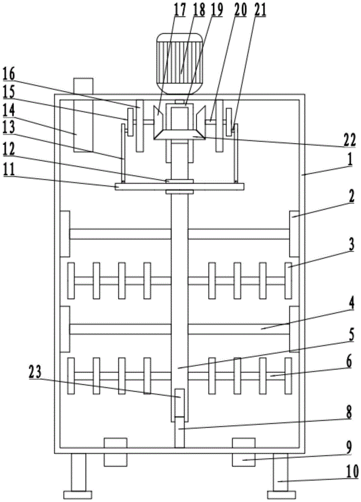
Figure 202120320102

The utility model discloses an electric mixer with an anti-hanging wall, which relates to the technical field of mixers. The inner top wall is rotatably connected to the installation cylinder, the top of the rotation column extends into the rotation column, and is slidably connected up and down with the installation cylinder. The limit column extends into the through groove and is in active contact with the rotating column. The rotating column is fixedly connected to the stirring rod, the stirring rod is fixedly connected to the stirring blade, and the upper end of the rotating column below the installation cylinder is fixedly connected to the limit block, the limit block A linkage rod is movably sleeved on the rotating column between them, the device structure and principle are reasonably designed, the operation and use are convenient, and the practicability is high.

Figure 202120320102

Description

Prevent electric mixer of wall built-up
Technical Field
The utility model relates to an agitator motor technical field specifically is a prevent electric mixer of wall built-up.
Background
A stirrer is a machine which is provided with blades and a shaft rotating in a cylinder or a groove and stirs and mixes a plurality of raw materials to form a mixture or a proper consistency, and the stirrer is divided into a plurality of types, such as a forced stirrer, a single horizontal shaft stirrer, a double horizontal shaft stirrer and the like.
And need use corresponding mixer sometimes in some food processing's field, carry out abundant mixing stirring with food raw materials, and then reach the purpose of making different food, but traditional mixer is when using, the condition of material adhesion on the inner wall can appear sometimes, leads to food raw materials's waste, and traditional mixer has stirring inefficiency simultaneously, stirs inhomogeneous condition, and the practicality is not high.
SUMMERY OF THE UTILITY MODEL
The utility model provides a prevent electric mixer of wall built-up has solved the problem that goes out among the above-mentioned background art.
In order to achieve the above object, the utility model provides a following technical scheme:
the utility model provides a prevent electric mixer of wall built-up, includes the installation shell, installation shell bottom both sides fixed connection installation leg, set up the rotation post in the installation shell, the roof rotates in the installation shell of rotation post top and connects the installation section of thick bamboo, rotate the capital end and extend to in rotating the post, and with installation section of thick bamboo upper and lower sliding connection, it sets up logical groove to rotate the post lower extreme, and the spacing post of bottom fixed connection extends to logical inslot in the installation shell of logical groove below, and with rotation post active contact, fixed connection puddler on the rotation post, fixed connection stirring leaf on the puddler, rotation post upper end fixed connection stopper of installation section of thick bamboo below, the movable linkage rod that cup joints on the rotation post between the stopper.
As a preferred technical scheme of the utility model, first bevel gear is cup jointed to the last fixed of installation cylinder, and top fixed connection fixed plate in the installation shell of first bevel gear both sides rotates on the fixed plate and connects the erection column, erection column one side fixed connection second bevel gear, and second bevel gear is connected with first bevel gear meshing transmission, second bevel gear one side fixed connection drive wheel is kept away from to the erection column, fixed connection fixed axle on the drive wheel, rotates on the fixed axle and connects the transfer line, and the transfer line bottom is connected with the gangbar is articulated.
As a preferred technical scheme of the utility model, fixed connection installation pole on the rotation post of puddler top, installation pole one side fixed connection scraper blade, scraper blade and installation shell lateral wall sliding contact, rotation capital end fixed connection gag lever post, gag lever post extend to in the installation section of thick bamboo, and with installation section of thick bamboo sliding connection.
As a preferred technical scheme of the utility model, the installation shell top fixed connection driving motor of installation section of thick bamboo top, driving motor's output shaft bottom and installation section of thick bamboo fixed connection, the installation shell top fixed connection inlet pipe of driving motor one side, installation shell bottom both sides set up the bleeder valve.
As an optimized technical scheme of the utility model, the scraper blade is wooden material.
The utility model discloses have following useful part: the device has reasonable structural principle and design, is convenient to operate and use, and when in use, food raw materials to be mixed and stirred are placed in the mounting shell through the inlet pipe, then the driving mounting cylinder of the driving motor is started to rotate, the rotating column is driven to rotate under the action of the limiting rod at the upper end of the rotating column, the first bevel gear on the mounting cylinder drives the second bevel gear to rotate, and further drives the driving wheel to rotate, the linkage rod is driven to move up and down under the action of the transmission rod, the rotating column is driven to move up and down under the action of the limiting block, the stirring rod and the stirring blades on the rotating column can move up and down for stirring while rotating and stirring, the stirring and mixing efficiency of the materials is further improved, meanwhile, the scraper at one side of the mounting rod on the mounting column moves down along with the rotation, the comprehensive scraping of the materials on the inner wall of the mounting shell is realized, the raw materials are saved, and the cost is reduced, the practicability is higher.
Drawings
FIG. 1 is a schematic view of a structure of a wall-hanging prevention electric mixer.
FIG. 2 is a schematic view of a driving wheel of an anti-wall-hanging electric mixer.
Fig. 3 is a schematic structural view of an installation barrel and a limiting rod in an anti-wall-hanging electric mixer.
In the figure: 1. mounting a shell; 2. a squeegee; 3. stirring blades; 4. mounting a rod; 5. rotating the column; 6. a stirring rod; 7. a limiting rod; 8. a limiting column; 9. a discharge valve; 10. mounting legs; 11. a linkage rod; 12. a limiting block; 13. a transmission rod; 14. a feed pipe; 15. a driving wheel; 16. a fixing plate; 17. a second bevel gear; 18. a drive motor; 19. mounting the cylinder; 20. mounting a column; 21. a fixed shaft; 22. a first bevel gear; 23. a through groove.
Detailed Description
The preferred embodiments of the present invention will be described in conjunction with the accompanying drawings, and it will be understood that they are presented herein only to illustrate and explain the present invention, and not to limit the present invention.
It should be noted that the terms "center", "upper", "lower", "left", "right", "vertical", "horizontal", "inner", "outer", etc. indicate orientations or positional relationships based on the orientations or positional relationships shown in the drawings, and are only for convenience of describing the present invention and simplifying the description, but do not indicate or imply that the device or element referred to must have a specific orientation, be constructed in a specific orientation, and be operated, and thus should not be construed as limiting the present invention.
Example 1
Referring to fig. 1-3, an anti-wall-hanging electric mixer comprises an installation shell 1, wherein two sides of the bottom of the installation shell 1 are fixedly connected with installation legs 10, a rotation column 5 is arranged in the installation shell 1, the top wall of the installation shell 1 above the rotation column 5 is rotatably connected with an installation cylinder 19, the top end of the rotation column 5 extends into the rotation column 5 and is connected with the installation cylinder 19 in an up-and-down sliding manner, a through groove 23 is formed in the lower end of the rotation column 5, a limiting column 8 is fixedly connected to the bottom of the installation shell 1 below the through groove 23, the limiting column 8 extends into the through groove 23 and is in movable contact with the rotation column 5, a stirring rod 6 is fixedly connected to the rotation column 5, a stirring blade 3 is fixedly connected to the stirring rod 6, a limiting block 12 is fixedly connected to the upper end of the rotation column 5 below the installation cylinder 19, and a linkage rod 11 is movably sleeved on the rotation column 5 between the limiting blocks 12.
The mounting barrel 19 is fixedly sleeved with a first bevel gear 22, the top of the inside of the mounting shell 1 on two sides of the first bevel gear 22 is fixedly connected with a fixing plate 16, the fixing plate 16 is rotatably connected with a mounting column 20, one side of the mounting column 20 is fixedly connected with a second bevel gear 17, the second bevel gear 17 is in meshing transmission connection with the first bevel gear 22, one side of the mounting column 20, far away from the second bevel gear 17, is fixedly connected with a driving wheel 15, the driving wheel 15 is fixedly connected with a fixed shaft 21, the fixed shaft 21 is rotatably connected with a transmission rod 13, and the bottom of the transmission rod 13 is hinged with the linkage rod 11.
Fixed connection installation pole 4 on the rotation post 5 of puddler 6 top, 4 one side fixed connection scraper blades 2 of installation pole, scraper blade 2 and the 1 lateral wall sliding contact of installation shell, 5 top fixed connection gag lever posts 7 of rotation post, gag lever post 7 extend to in the installation section of thick bamboo 19, and with installation section of thick bamboo 19 sliding connection.
The top fixed connection driving motor 18 of installation shell 1 of installation section of thick bamboo 19 top, driving motor 18's output shaft bottom and installation section of thick bamboo 19 fixed connection, 1 top fixed connection inlet pipe 14 of installation shell of driving motor 18 one side, 1 bottom both sides of installation shell set up bleeder valve 9.
Example 2
Referring to fig. 1-3, the other contents of the present embodiment are the same as embodiment 1, except that: the scraper 2 is made of wood.
In the implementation process of the utility model, when in use, food raw materials to be mixed and stirred are placed in the installation shell 1 through the inlet pipe 14, then the driving installation cylinder 19 of the driving motor 18 is started to rotate, the rotating column 5 is driven to rotate under the action of the limiting rod 7 at the upper end of the rotating column 19, the first bevel gear 22 on the installation cylinder 19 drives the second bevel gear 17 to rotate, further the driving wheel 15 is driven to rotate, the linkage rod 11 is driven to move up and down under the action of the transmission rod 13, the rotating column 5 is driven to move up and down under the action of the limiting block 12, the stirring rod 6 and the stirring blade 3 on the rotating column 5 can move up and down for stirring while rotating for stirring, the stirring and mixing efficiency of the materials is further improved, meanwhile, the scraping plate 2 on one side of the installation rod 4 on the rotating column 5 moves down while rotating, so as to realize comprehensive scraping of the materials on the inner wall of the installation shell 1, the raw materials of saving, the cost is reduced, the practicality is higher, and the device structure principle reasonable in design on the whole, operation use is convenient.
Finally, it should be noted that: although the present invention has been described in detail with reference to the foregoing embodiments, it will be apparent to those skilled in the art that modifications may be made to the embodiments described in the foregoing embodiments, or equivalents may be substituted for elements thereof. Any modification, equivalent replacement, or improvement made within the spirit and principle of the present invention should be included in the protection scope of the present invention.

Claims (5)

1. The anti-wall-hanging electric mixer comprises a mounting shell (1) and is characterized in that mounting legs (10) are fixedly connected to two sides of the bottom of the mounting shell (1), a rotating column (5) is arranged in the mounting shell (1), the top wall of the mounting shell (1) above the rotating column (5) is rotatably connected with a mounting cylinder (19), the top end of the rotating column (5) extends into the rotating column (5) and is in sliding connection with the mounting cylinder (19) up and down, a through groove (23) is formed at the lower end of the rotating column (5), a limiting column (8) is fixedly connected to the bottom of the mounting shell (1) below the through groove (23), the limiting column (8) extends into the through groove (23) and is in movable contact with the rotating column (5), a stirring rod (6) is fixedly connected to the rotating column (5), a stirring blade (3) is fixedly connected to the stirring rod (6), and a limiting block (12) is fixedly connected to the upper end of the rotating column (5) below the mounting cylinder (19), the rotating column (5) between the limiting blocks (12) is movably sleeved with a linkage rod (11).
2. The anti-wall-hanging electric mixer as claimed in claim 1, wherein the mounting cylinder (19) is fixedly sleeved with a first bevel gear (22), the top parts of the inside of the mounting shells (1) at the two sides of the first bevel gear (22) are fixedly connected with a fixing plate (16), the fixing plate (16) is rotatably connected with a mounting column (20), one side of the mounting column (20) is fixedly connected with a second bevel gear (17), the second bevel gear (17) is in meshing transmission connection with the first bevel gear (22), one side of the mounting column (20) far away from the second bevel gear (17) is fixedly connected with a driving wheel (15), the driving wheel (15) is fixedly connected with a fixing shaft (21), the fixing shaft (21) is rotatably connected with a transmission rod (13), and the bottom of the transmission rod (13) is hinged to a linkage rod (11).
3. The anti-hanging electric mixer as claimed in claim 2, wherein the rotating column (5) above the mixing rod (6) is fixedly connected with the mounting rod (4), one side of the mounting rod (4) is fixedly connected with the scraper (2), the scraper (2) is in sliding contact with the side wall of the mounting shell (1), the top end of the rotating column (5) is fixedly connected with the limiting rod (7), and the limiting rod (7) extends into the mounting cylinder (19) and is in sliding connection with the mounting cylinder (19).
4. The anti-wall-hanging electric mixer as claimed in claim 3, characterized in that the top of the mounting shell (1) above the mounting barrel (19) is fixedly connected with the driving motor (18), the bottom of the output shaft of the driving motor (18) is fixedly connected with the mounting barrel (19), the top of the mounting shell (1) on one side of the driving motor (18) is fixedly connected with the feeding pipe (14), and the two sides of the bottom of the mounting shell (1) are provided with the discharge valves (9).
5. An anti-hang up electric mixer as claimed in claim 3 or 4, wherein the scraping plate (2) is made of wood.
CN202120320102.7U 2021-02-04 2021-02-04 A wall-mounted electric mixer Active CN214553044U (en)

Priority Applications (1)

Application Number Priority Date Filing Date Title
CN202120320102.7U CN214553044U (en) 2021-02-04 2021-02-04 A wall-mounted electric mixer

Applications Claiming Priority (1)

Application Number Priority Date Filing Date Title
CN202120320102.7U CN214553044U (en) 2021-02-04 2021-02-04 A wall-mounted electric mixer

Publications (1)

Publication Number Publication Date
CN214553044U true CN214553044U (en) 2021-11-02

Family

ID=78315673

Family Applications (1)

Application Number Title Priority Date Filing Date
CN202120320102.7U Active CN214553044U (en) 2021-02-04 2021-02-04 A wall-mounted electric mixer

Country Status (1)

Country Link
CN (1) CN214553044U (en)

Cited By (1)

* Cited by examiner, † Cited by third party
Publication number Priority date Publication date Assignee Title
CN116476237A (en) * 2023-04-26 2023-07-25 中建八局第一建设有限公司 A temporary storage device for on-site construction

Cited By (1)

* Cited by examiner, † Cited by third party
Publication number Priority date Publication date Assignee Title
CN116476237A (en) * 2023-04-26 2023-07-25 中建八局第一建设有限公司 A temporary storage device for on-site construction

Similar Documents

Publication Publication Date Title
CN214773185U (en) Plastic stirring machine
CN207206742U (en) A kind of mixer for building for being easy to cleaning
CN217795833U (en) High-efficient machine that mixes of biax paddle is used in pentosan and flour fusion
CN220194652U (en) Multi-angle mixing's mixer
CN220609985U (en) Stirring and mixing device for extracting zeaxanthin by biological enzyme method
CN220091155U (en) Self-rotating type central stirring equipment
CN218365601U (en) Mortar mixer with clearance function
CN216224062U (en) Efficient double-horizontal-shaft mixer
CN215540149U (en) Agitating unit of food processing usefulness
CN213314383U (en) Horizontal stirring tank
CN213078123U (en) Asphalt modifier low-speed mixer
CN212021214U (en) Novel stirring machine
CN211514301U (en) Raw material mixing and stirring device
CN224027991U (en) Novel concrete mixer
CN219902696U (en) Reciprocating cement paste mixer
CN220546897U (en) SBS modified asphalt mixing machine
CN217093034U (en) Novel double-shaft mixer
CN216572622U (en) Mixer is used in concrete additive production
CN223604719U (en) Blending stirring device for modified plastic production
CN219650257U (en) Efficient stirrer with multilayer stirring structure
CN214715881U (en) High-efficient agitating unit and mixer
CN223945481U (en) Mixing arrangement is used in aqueous emulsion production
CN223439717U (en) A dual-shaft high-efficiency premixed feed mixer
CN220614472U (en) Efficient stirring mechanism of stirrer
CN222093119U (en) A food mixer

Legal Events

Date Code Title Description
GR01 Patent grant
GR01 Patent grant
PE01 Entry into force of the registration of the contract for pledge of patent right

Denomination of utility model: An electric mixer for preventing wall hanging

Effective date of registration: 20230316

Granted publication date: 20211102

Pledgee: Dongying Rural Commercial Bank Co.,Ltd.

Pledgor: Shandong Yuanzheng Testing Technology Co.,Ltd.

Registration number: Y2023980034953

PC01 Cancellation of the registration of the contract for pledge of patent right

Granted publication date: 20211102

Pledgee: Dongying Rural Commercial Bank Co.,Ltd.

Pledgor: Shandong Yuanzheng Testing Technology Co.,Ltd.

Registration number: Y2023980034953

PC01 Cancellation of the registration of the contract for pledge of patent right
PE01 Entry into force of the registration of the contract for pledge of patent right

Denomination of utility model: An electric mixer with anti hanging wall

Granted publication date: 20211102

Pledgee: Dongying Rural Commercial Bank Co.,Ltd.

Pledgor: Shandong Yuanzheng Testing Technology Co.,Ltd.

Registration number: Y2024980007040

PE01 Entry into force of the registration of the contract for pledge of patent right
PC01 Cancellation of the registration of the contract for pledge of patent right

Granted publication date: 20211102

Pledgee: Dongying Rural Commercial Bank Co.,Ltd.

Pledgor: Shandong Yuanzheng Testing Technology Co.,Ltd.

Registration number: Y2024980007040

PC01 Cancellation of the registration of the contract for pledge of patent right
PE01 Entry into force of the registration of the contract for pledge of patent right

Denomination of utility model: An anti wall electric mixer

Granted publication date: 20211102

Pledgee: Dongying Rural Commercial Bank Co.,Ltd.

Pledgor: Shandong Yuanzheng Testing Technology Co.,Ltd.

Registration number: Y2025980007158

PE01 Entry into force of the registration of the contract for pledge of patent right
PC01 Cancellation of the registration of the contract for pledge of patent right

Granted publication date: 20211102

Pledgee: Dongying Rural Commercial Bank Co.,Ltd.

Pledgor: Shandong Yuanzheng Testing Technology Co.,Ltd.

Registration number: Y2025980007158

PC01 Cancellation of the registration of the contract for pledge of patent right
PE01 Entry into force of the registration of the contract for pledge of patent right

Denomination of utility model: An electric mixer for preventing wall hanging

Granted publication date: 20211102

Pledgee: Dongying Rural Commercial Bank Co.,Ltd.

Pledgor: Shandong Yuanzheng Testing Technology Co.,Ltd.

Registration number: Y2026980008157

PE01 Entry into force of the registration of the contract for pledge of patent right