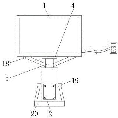
Display board mounting structure
Technical Field
The utility model relates to a show board mounting structure.
Background
Traditional show board mounting structure is not convenient for adjust, can't adjust display device's height, can influence the bandwagon effect in information display device later stage, can't be comprehensive demonstrate to the learner.
Disclosure of Invention
An object of the utility model is to provide a show board mounting structure possesses the advantage of being convenient for adjust, has solved the problem that current show board mounting structure is not convenient for adjust.
In order to achieve the above object, the utility model provides a following technical scheme:
a display board mounting structure comprises a display board and a shell, wherein the back of the display board is movably connected with a fixed seat through a movable shaft, the back of the fixed seat is fixedly connected with a fixed column, the bottom of the fixed column is fixedly connected with a fixed rod, the bottom of the fixed rod penetrates into the inner cavity of the shell, the bottom of the fixed column is provided with an installation groove, a rack plate is fixedly connected to the right side of the inner cavity of the mounting groove, a gear is meshed with the top of the surface of the rack plate, the axis of the gear is sleeved with a rotating shaft, the back surface of the rotating shaft penetrates through the top of the back surface of the shell, the back of the rotating shaft is fixedly connected with a turntable, the bottom of the back of the fixed column is provided with a miniature electric push rod, the front of the miniature electric push rod penetrates through the front of the fixed column and is fixedly connected with a movable seat, and the front of the movable seat is movably connected with the bottom of the back of the display board through a movable shaft.
Preferably, the bottom fixedly connected with fixed block of carousel, the back of fixed block is provided with the fixed pin, the front of fixed pin run through to the front of fixed block and with the top threaded connection at the casing back.
Preferably, the bottom of the miniature electric push rod is fixedly connected with a mounting plate, and the front face of the mounting plate is fixedly connected with the back face of the fixing column.
Preferably, the connecting seat is fixedly connected to the top of the front of the fixing column, the front of the connecting seat is movably connected with the movable block through the movable rod, and the front of the movable block is fixedly connected with the top of the back of the display board.
Preferably, the front side and the rear side of the inner cavity of the shell are both provided with sliding grooves, the inner cavity of each sliding groove is connected with a sliding block in a sliding mode, and the inner sides of the sliding blocks are fixedly connected with the front bottom and the back bottom of the fixing rod.
Preferably, the both sides of show board bottom are all fixedly connected with branch, the inboard both sides fixed connection with the dead lever of branch, the bottom fixedly connected with stabilizing block of casing both sides, the bottom fixedly connected with support of stabilizing block.
Preferably, the bottom of the shell is fixedly connected with a bottom plate, two sides of the top of the bottom plate are fixedly connected with the top of the support, and the bottom of the bottom plate is fixedly connected with an anti-skid pad.
Compared with the prior art, the beneficial effects of the utility model are as follows:
1. the utility model discloses a setting of fixing base, fixed column, dead lever, mounting groove, rack plate, gear, pivot, carousel, miniature electric push rod, sliding seat, fixed block and fixed pin has reached the advantage of being convenient for to adjust, has solved the problem that current show board mounting structure is not convenient for adjust, can highly adjust display device, can not influence the bandwagon effect in confidence display device later stage, can be comprehensive like the learner demonstrates, can not influence information display device's result of use.
2. The utility model discloses a set up the mounting panel, play fixed effect to miniature electric push rod, miniature electric push rod is better when using like this, it rocks to have avoided miniature electric push rod to appear when using, also be convenient for people to fix miniature electric push rod simultaneously, through setting up fixed block and fixed pin, the effect of stable rotation has been played to the carousel, stability when having increased the carousel rotation, prevent that the carousel from appearing rocking the problem after placing, mutually support through setting up slider and spout, play the effect of reducing friction to dead lever and casing, it is too big to have solved dead lever and casing because frictional force when using, the phenomenon of damage appears, stability when having increased the dead lever and having removed, the life of dead lever and casing has been prolonged.
Drawings
FIG. 1 is a schematic structural view of the present invention;
FIG. 2 is a left side view of the display board and fixing post structure of the present invention;
fig. 3 is a left side sectional view of the housing and the mounting groove structure of the present invention.
In the figure: 1. a display board; 2. a housing; 3. a fixed seat; 4. fixing a column; 5. fixing the rod; 6. mounting grooves; 7. a rack plate; 8. a gear; 9. a rotating shaft; 10. a turntable; 11. a miniature electric push rod; 12. a movable seat; 13. a fixed block; 14. a fixing pin; 15. mounting a plate; 16. a chute; 17. a slider; 18. a strut; 19. a stabilizing block; 20. a base plate.
Detailed Description
Referring to fig. 1-3, a display board mounting structure includes a display board 1 and a housing 2, the back of the display board 1 is movably connected with a fixing base 3 through a movable shaft, the back of the fixing base 3 is fixedly connected with a fixing column 4, the bottom of the fixing column 4 is fixedly connected with a fixing rod 5, the bottom of the fixing rod 5 penetrates through the inner cavity of the housing 2, the bottom of the fixing column 4 is provided with a mounting groove 6, the right side of the inner cavity of the mounting groove 6 is fixedly connected with a rack plate 7, the top of the surface of the rack plate 7 is engaged with a gear 8, the axis of the gear 8 is sleeved with a rotating shaft 9, the back of the rotating shaft 9 penetrates through the top of the back of the housing 2, the back of the rotating shaft 9 is fixedly connected with a turntable 10, the bottom of the back of the fixing column 4 is provided with a micro electric push rod 11, the front of the micro electric push rod 11 penetrates through the front of the fixing column 4 and is fixedly connected with a movable seat 12, and the front of the movable seat 12 is movably connected with the bottom of the back of the display board 1 through the movable shaft;
the bottom of the rotary table 10 is fixedly connected with a fixed block 13, the back of the fixed block 13 is provided with a fixed pin 14, the front of the fixed pin 14 penetrates through the front of the fixed block 13 and is in threaded connection with the top of the back of the shell 2, and the mounting plate 15 is arranged to fix the miniature electric push rod 11, so that the miniature electric push rod 11 has a better effect in use, the miniature electric push rod 11 is prevented from shaking in use, and meanwhile, people can conveniently fix the miniature electric push rod 11;
the bottom of the miniature electric push rod 11 is fixedly connected with an installation plate 15, the front surface of the installation plate 15 is fixedly connected with the back surface of the fixed column 4, and the fixed block 13 and the fixed pin 14 are arranged, so that the turntable 10 is stabilized in rotation, the stability of the turntable 10 in rotation is improved, and the problem that the turntable 10 shakes after being placed is solved;
the connecting seat is fixedly connected to the top of the front side of the fixed column 4, the front side of the connecting seat is movably connected with the movable block through the movable rod, the front side of the movable block is fixedly connected with the top of the back side of the display board 1, the sliding block 17 and the sliding groove 16 are arranged to be matched with each other, a friction reducing effect is achieved on the fixed rod 5 and the shell 2, the problem that the fixed rod 5 and the shell 2 are damaged due to overlarge friction force when in use is solved, the stability of the fixed rod 5 during moving is improved, and the service lives of the fixed rod 5 and the shell 2 are prolonged;
the front side and the rear side of the inner cavity of the shell 2 are both provided with sliding grooves 16, the inner cavity of the sliding grooves 16 is connected with sliding blocks 17 in a sliding manner, and the inner sides of the sliding blocks 17 are fixedly connected with the bottoms of the front surface and the back surface of the fixed rod 5;
the two sides of the bottom of the display board 1 are fixedly connected with supporting rods 18, the inner sides of the supporting rods 18 are fixedly connected with the two sides of the fixing rod 5, the bottoms of the two sides of the shell 2 are fixedly connected with stabilizing blocks 19, and the bottoms of the stabilizing blocks 19 are fixedly connected with a support;
bottom fixedly connected with bottom plate 20 of casing 2, the both sides at bottom plate 20 top and the top fixed connection of support, the bottom fixedly connected with slipmat of bottom plate 20, through fixing base 3, fixed column 4, dead lever 5, mounting groove 6, rack plate 7, gear 8, pivot 9, carousel 10, miniature electric putter 11, sliding seat 12, the setting of fixed block 13 and fixed pin 14, the advantage of being convenient for to adjust has been reached, the problem of the regulation of being not convenient for of display board mounting structure that has solved the current computer specialty and uses, can highly adjust display device, can not influence the bandwagon effect in confidence display device later stage, can be comprehensive like the learner to demonstrate, can not influence information display device's result of use.
When the micro electric push rod 11 is used, a user opens the micro electric push rod 11 through an external controller, the micro electric push rod 11 is fixed through the arrangement of the mounting plate 15, so that the micro electric push rod 11 has a better effect when in use, the micro electric push rod 11 is prevented from shaking when in use, meanwhile, people can conveniently fix the micro electric push rod 11, the micro electric push rod 11 drives the display board 1 to carry out angle adjustment through the movable seat 12, the connecting seat, the movable rod and the movable block, so that the inclination angle of the display board 1 can be displayed according to requirements, when the height of the display board 1 is required to be adjusted, the user drives the rotating shaft 9 to rotate through the turntable 10, the rotating shaft 9 drives the gear 8 to rotate, the gear 8 drives the fixed rod 5 to move upwards through the rack plate 7, the fixed rod 5 drives the fixed column 4 to move upwards through the sliding block 17 and the sliding groove 16, and the sliding block 17 and the sliding groove 16 are mutually matched, the fixing rod 5 and the shell 2 are provided with the function of reducing friction, the phenomenon that the fixing rod 5 and the shell 2 are damaged due to overlarge friction force when in use is solved, the stability when the fixing rod 5 moves is improved, the service lives of the fixing rod 5 and the shell 2 are prolonged, the fixing column 4 drives the display board 1 to be adjusted in height through the movable seat 12 and the supporting rod 18, the height of the display board 1 can be adjusted according to requirements, the practicability of the device is improved, the fixing block 13 and the fixing pin 14 are arranged, the rotating disc 10 is stabilized in rotation, the stability when the rotating disc 10 rotates is improved, the problem that the rotating disc 10 shakes after being placed is prevented, the advantage of convenient adjustment is achieved, the problem that the display board mounting structure specially used by the existing computer is not convenient to adjust is solved, and the height of the display device can be adjusted, the display effect at the later stage of the information display device can not be influenced, the information display device can be comprehensively displayed for learners, and the using effect of the information display device can not be influenced.