CN214535444U - Oil well energy recovery device - Google Patents
Oil well energy recovery device Download PDFInfo
- Publication number
- CN214535444U CN214535444U CN202120459320.9U CN202120459320U CN214535444U CN 214535444 U CN214535444 U CN 214535444U CN 202120459320 U CN202120459320 U CN 202120459320U CN 214535444 U CN214535444 U CN 214535444U
- Authority
- CN
- China
- Prior art keywords
- fixedly connected
- bottom plate
- close
- well energy
- umbrella
- Prior art date
- Legal status (The legal status is an assumption and is not a legal conclusion. Google has not performed a legal analysis and makes no representation as to the accuracy of the status listed.)
- Active
Links
- 239000003129 oil well Substances 0.000 title claims abstract description 12
- 238000011084 recovery Methods 0.000 title claims description 12
- 238000000605 extraction Methods 0.000 claims abstract description 8
- 230000002146 bilateral effect Effects 0.000 claims description 2
- 230000000694 effects Effects 0.000 abstract description 8
- 230000017525 heat dissipation Effects 0.000 abstract description 7
- 238000009423 ventilation Methods 0.000 abstract description 5
- 241000883990 Flabellum Species 0.000 abstract description 3
- 238000009434 installation Methods 0.000 description 8
- 230000005540 biological transmission Effects 0.000 description 2
- 238000000034 method Methods 0.000 description 2
- 238000005086 pumping Methods 0.000 description 2
- 230000004075 alteration Effects 0.000 description 1
- 230000009286 beneficial effect Effects 0.000 description 1
- 230000007547 defect Effects 0.000 description 1
- 238000010586 diagram Methods 0.000 description 1
- 239000000284 extract Substances 0.000 description 1
- 238000012986 modification Methods 0.000 description 1
- 230000004048 modification Effects 0.000 description 1
- 230000003014 reinforcing effect Effects 0.000 description 1
- 230000003068 static effect Effects 0.000 description 1
- 238000006467 substitution reaction Methods 0.000 description 1
Images

Landscapes
- Hydraulic Motors (AREA)
Abstract
The utility model discloses an oil well energy recuperation device, comprising a base plate, the top fixedly connected with installing frame of bottom plate, and the top of installing frame installs the device body, the motor is installed to the bottom of bottom plate, there is thick pole at the top of bottom plate through bearing swing joint, and the output shaft fixed connection of the bottom of thick pole and motor, the top fixedly connected with flabellum of thick pole, a plurality of ventilation hole has been seted up at the top of installing frame, install first umbrella type gear on the thick pole, and the left and right sides of first umbrella type gear all meshes there is the second umbrella type gear, one side that two second umbrella type gears kept away from mutually all is through the left and right sides inner wall swing joint of horizontal pole and bearing and installing frame. The utility model discloses a mutually supporting of motor, flabellum, ventilation hole, air extractor, movable block, spring, cam, exhaust tube, standpipe and extraction opening makes the heat dissipation of device body more thoroughly comprehensive, the effectual radiating effect that has strengthened.
Description
Technical Field
The utility model relates to a power equipment technical field specifically is oil well energy recuperation device.
Background
In the electric power field, because different electric equipment and electric sites have rated voltage and frequency requirements, in order to ensure that the voltage and frequency of the connected power transmission end are matched with the electric equipment to be used, the output power of the power transmission end needs to be converted by an oil well energy recovery device and then used by the electric equipment. However, the oil well energy recovery device in the prior art is poor in heat dissipation effect, inconvenient to work, inconvenient to move and poor in use effect, and therefore the oil well energy recovery device is provided.
SUMMERY OF THE UTILITY MODEL
The utility model provides a technical problem lie in overcoming prior art's radiating effect poor with remove defects such as not convenient, provide oil well energy recuperation device. The oil well energy recovery device has the characteristics of good heat dissipation effect, convenience in moving and the like.
In order to achieve the above object, the utility model provides a following technical scheme: the oil well energy recovery device comprises a bottom plate, wherein the top of the bottom plate is fixedly connected with an installation frame, the top of the installation frame is provided with a device body, the bottom of the bottom plate is provided with a motor, the top of the bottom plate is movably connected with a thick rod through a bearing, the bottom end of the thick rod is fixedly connected with an output shaft of the motor, the top end of the thick rod is fixedly connected with fan blades, the top of the installation frame is provided with a plurality of ventilation holes, the thick rod is provided with a first umbrella-shaped gear, the left side and the right side of the first umbrella-shaped gear are respectively engaged with a second umbrella-shaped gear, one side far away from the two second umbrella-shaped gears is movably connected with the inner walls of the left side and the right side of the installation frame through a transverse rod and a bearing, one end far away from the two transverse rods respectively penetrates through a cam fixedly connected with an inner ring of the bearing, the positions, close to the left side and the right side, of the top of the bottom plate are respectively provided with a T-shaped rod, and the two T-shaped rods are respectively connected with an air extractor in a sliding manner, two equal fixedly connected with two montants in bottom of air extractor, two the top of cam all is equipped with the diaphragm, and the bottom of two diaphragms contacts with the top of two cams respectively to the top of two diaphragms respectively with the bottom fixed connection of four montants, two the exhaust tube is all installed to one side that the air extractor is close to, and the equal fixedly connected with standpipe of one end that two exhaust tubes are close to mutually to a plurality of extraction opening has all been seted up to one side that two standpipe are close to mutually.
Preferably, two all the cover is equipped with two movable blocks on the T shape pole, and all set up in four movable blocks rather than assorted through-hole, two one side that the air extractor was kept away from respectively with four movable block fixed connection, two all the cover is equipped with the spring on the T shape pole, and the top and the bottom of two springs are close to left and right sides department and the bottom fixed connection of two movable blocks that are located the below with the top of bottom plate respectively.
Preferably, the bottom of the bottom plate is close to the equal fixedly connected with straight-bar in four corners, and the bottom of four straight-bars all has the universal wheel swing joint, is located two of front side the universal wheel uses the central axis of bottom plate to be the symmetry axis and is bilateral symmetry setting.
Preferably, the left sides of the four straight rods are movably connected with self-locking plates matched with universal wheels.
Preferably, the bottom of bottom plate is close to the equal fixedly connected with electric telescopic handle of left and right sides department, and the equal fixedly connected with backup pad in bottom of two electric telescopic handle.
Compared with the prior art, the beneficial effects of the utility model are that: in this technical scheme, through mutually supporting of motor, flabellum, ventilation hole, air extractor, movable block, spring, cam, exhaust tube, standpipe and extraction opening, make the heat dissipation of device body thoroughly more comprehensive, the effectual radiating effect that has strengthened, and the setting of universal wheel and auto-lock board realizes that the drive device body removes and is static, and the setting of electric telescopic handle and backup pad realizes the auxiliary stay, the effectual stability that has improved.
Drawings
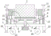
FIG. 1 is an overall structure diagram of the present invention;
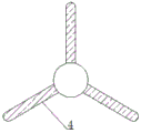
FIG. 2 is a top view of the fan blade of FIG. 1;
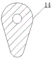
FIG. 3 is a side view of the cam of FIG. 1;
fig. 4 is an enlarged view of a point a in fig. 1.
Reference numbers in the figures: 1. a base plate; 2. installing a frame; 3. a motor; 4. a fan blade; 5. a thick rod; 6. a vent hole; 7. a device body; 8. a first bevel gear; 9. a second bevel gear; 10. an air extractor; 11. a T-shaped rod; 12. a movable block; 13. a spring; 14. a cam; 15. a transverse plate; 16. a vertical rod; 17. an air exhaust pipe; 18. a vertical tube; 19. an air extraction opening; 20. a universal wheel; 21. a self-locking plate; 22. an electric telescopic rod; 23. and a support plate.
Detailed Description
The technical solutions in the embodiments of the present invention will be described clearly and completely with reference to the accompanying drawings in the embodiments of the present invention, and it is obvious that the described embodiments are only some embodiments of the present invention, not all embodiments. Based on the embodiments in the present invention, all other embodiments obtained by a person skilled in the art without creative work belong to the protection scope of the present invention.
Referring to fig. 1-4, the present invention provides a technical solution: the oil well energy recovery device comprises a bottom plate 1, wherein the top of the bottom plate 1 is fixedly connected with an installation frame 2, the top of the installation frame 2 is provided with a device body 7, the bottom of the bottom plate 1 is provided with a motor 3, the top of the bottom plate 1 is movably connected with a thick rod 5 through a bearing, the bottom end of the thick rod 5 is fixedly connected with an output shaft of the motor 3, the top end of the thick rod 5 is fixedly connected with a fan blade 4, the top of the installation frame 2 is provided with a plurality of ventilation holes 6, the thick rod 5 is provided with a first bevel gear 8, the left side and the right side of the first bevel gear 8 are respectively meshed with a second bevel gear 9, the far sides of the two second bevel gears 9 are respectively movably connected with the inner walls of the left side and the right side of the installation frame 2 through transverse rods and bearings, the far ends of the two transverse rods respectively penetrate through a bearing inner ring to be fixedly connected with cams 14, the top of the bottom plate 1 is provided with T-shaped rods 11 near the left side and the right sides, the two T-shaped rods 11 are respectively connected with an air pump 10 in a sliding manner, the two T-shaped rods 11 are respectively sleeved with two movable blocks 12, the four movable blocks 12 are respectively provided with through holes matched with the through holes, the far side of the two air pumps 10 is respectively fixedly connected with the four movable blocks 12, the two T-shaped rods 11 are respectively sleeved with springs 13, the top ends and the bottom ends of the two springs 13 are respectively fixedly connected with the positions, close to the left and right sides, of the top of the bottom plate 1 and the bottoms of the two movable blocks 12 positioned below, the bottoms of the two air pumps 10 are respectively fixedly connected with two vertical rods 16, the tops of the two cams 14 are respectively provided with transverse plates 15, the bottoms of the two transverse plates 15 are respectively contacted with the tops of the two cams 14, the tops of the two transverse plates 15 are respectively fixedly connected with the bottom ends of the four vertical rods 16, one side, close to the two air pumps 10, is respectively provided with an air pumping pipe 17, and one end, close to the two air pumping pipes 17, is respectively and fixedly connected with a vertical pipe 18, and one side of the two vertical pipes 18 close to each other is provided with a plurality of air extraction ports 19, through the mutual matching of the motor 3, the fan blades 4, the air vents 6, the air extractor 10, the movable block 12, the spring 13, the cam 14, the air extraction pipe 17, the vertical pipes 18 and the air extraction ports 19, the heat dissipation of the device body 7 is more thorough and comprehensive, the heat dissipation effect is effectively enhanced, straight bars are fixedly connected to the bottom of the bottom plate 1 close to four corners, the bottom ends of the four straight bars are movably connected with universal wheels 20, the two universal wheels 20 positioned on the front side are symmetrically arranged in the left-right direction by taking the central axis of the bottom plate 1 as a symmetry axis, self-locking plates 21 matched with the universal wheels 20 are movably connected to the left sides of the four straight bars, the universal wheels 20 and the self-locking plates 21 are arranged, the device body 7 is driven to move and stand still, electric telescopic rods 22 are fixedly connected to the bottom of the bottom plate 1 close to the left and right sides, and the equal fixedly connected with backup pad 23 in bottom of two electric telescopic handle 22, the setting of electric telescopic handle 22 and backup pad 23 realizes the auxiliary stay, the effectual stability that has improved.
The working principle is as follows: in the technical scheme, firstly, the self-locking plate 21 is pulled, the device body 7 is driven to move through the universal wheel 20, after the device body moves to a working area, the self-locking plate 21 is pulled to lock and fix the universal wheel 20, then the electric telescopic rod 22 is started to drive the supporting plate 23 to move downwards to be contacted with the ground, so as to realize auxiliary support and improve stability, a plurality of heat is generated in the working process of the device body 7, at the moment, the motor 3 and the air pump 10 are started, the motor 3 drives the fan blades 4 to rotate through the thick rod 5, wind generated by the rotation of the fan blades 4 is blown into the device body 7 through the vent holes 6 to dissipate heat, the air pump 10 extracts the heat generated on the device body 7 through the air exhaust pipe 17, the air exhaust port 19 and the vertical pipe 18 to further dissipate heat, the motor 3 drives the first umbrella-type gear 8 to rotate through the thick rod 5, the first umbrella-type gear 8 drives the second umbrella-type gear 9 to rotate, second umbrella gear 9 drives cam 14 and rotates, and cam 14 contacts through protruding end and diaphragm 15 at the rotation in-process, makes it drive diaphragm 15 and carries out the up-and-down motion, and diaphragm 15 drives air extractor 10 through montant 16 and carries out the up-and-down motion under the assistance of movable block 12 and spring 13, makes the heat dissipation more comprehensive, reinforcing radiating effect, the better work of the device body 7 of being convenient for.
Although embodiments of the present invention have been shown and described, it will be appreciated by those skilled in the art that changes, modifications, substitutions and alterations can be made in these embodiments without departing from the principles and spirit of the invention, the scope of which is defined in the appended claims and their equivalents.
Claims (5)
1. Oil well energy recuperation device, including bottom plate (1), its characterized in that: the device comprises a base plate (1), a mounting frame (2) is fixedly connected to the top of the base plate (1), a device body (7) is installed at the top of the mounting frame (2), a motor (3) is installed at the bottom of the base plate (1), a thick rod (5) is movably connected to the top of the base plate (1) through a bearing, the bottom end of the thick rod (5) is fixedly connected with an output shaft of the motor (3), fan blades (4) are fixedly connected to the top end of the thick rod (5), a plurality of vent holes (6) are formed in the top of the mounting frame (2), a first umbrella-shaped gear (8) is installed on the thick rod (5), second umbrella-shaped gears (9) are meshed with the left side and the right side of the first umbrella-shaped gear (8), one sides, away from two second umbrella-shaped gears (9), are movably connected with the inner walls of the left side and the right side of the mounting frame (2) through transverse rods and bearings, and one ends, away from the two transverse rods, respectively, penetrate through bearing inner rings and are fixedly connected with cams (14), t shape pole (11) are all installed near left and right sides department to the top of bottom plate (1), and equal sliding connection has air extractor (10), two on two T shape poles (11) the equal fixedly connected with of bottom of air extractor (10) two montants (16), two the top of cam (14) all is equipped with diaphragm (15), and the bottom of two diaphragm (15) contacts with the top of two cam (14) respectively to the top of two diaphragm (15) respectively with the bottom fixed connection of four montants (16), two exhaust tube (17) are all installed to one side that air extractor (10) are close to mutually, and the equal fixedly connected with standpipe (18) of one end that two exhaust tube (17) are close to mutually to one side that two standpipe (18) are close to all seted up a plurality of extraction opening (19).
2. A well energy recovery device according to claim 1, characterized in that: two all the cover is equipped with two movable block (12) on T shape pole (11), and all offer rather than assorted through-hole in four movable block (12), two one side that air extractor (10) kept away from mutually is respectively with four movable block (12) fixed connection, two all the cover is equipped with spring (13) on T shape pole (11), and the top and the bottom of two spring (13) are close to the bottom fixed connection of two movable block (12) of left and right sides department and below with the top of bottom plate (1) respectively.
3. A well energy recovery device according to claim 1, characterized in that: the bottom of bottom plate (1) is close to the equal fixedly connected with straight-bar in four corners department, and the equal swing joint in bottom of four straight-bars has universal wheel (20), is located two of front side universal wheel (20) use the central axis of bottom plate (1) to be bilateral symmetry setting as the symmetry axis.
4. A well energy recovery device according to claim 3, wherein: the left sides of the four straight rods are movably connected with self-locking plates (21) matched with universal wheels (20).
5. A well energy recovery device according to claim 1, characterized in that: the bottom of bottom plate (1) is close to equal fixedly connected with electric telescopic handle (22) of left and right sides department, and the equal fixedly connected with backup pad (23) in bottom of two electric telescopic handle (22).
Priority Applications (1)
| Application Number | Priority Date | Filing Date | Title |
|---|---|---|---|
| CN202120459320.9U CN214535444U (en) | 2021-03-03 | 2021-03-03 | Oil well energy recovery device |
Applications Claiming Priority (1)
| Application Number | Priority Date | Filing Date | Title |
|---|---|---|---|
| CN202120459320.9U CN214535444U (en) | 2021-03-03 | 2021-03-03 | Oil well energy recovery device |
Publications (1)
| Publication Number | Publication Date |
|---|---|
| CN214535444U true CN214535444U (en) | 2021-10-29 |
Family
ID=78258853
Family Applications (1)
| Application Number | Title | Priority Date | Filing Date |
|---|---|---|---|
| CN202120459320.9U Active CN214535444U (en) | 2021-03-03 | 2021-03-03 | Oil well energy recovery device |
Country Status (1)
| Country | Link |
|---|---|
| CN (1) | CN214535444U (en) |
-
2021
- 2021-03-03 CN CN202120459320.9U patent/CN214535444U/en active Active
Similar Documents
| Publication | Publication Date | Title |
|---|---|---|
| CN208143074U (en) | A kind of spinning frame frequency converter cooling device | |
| CN207166305U (en) | A kind of rare earth permanent-magnet synchronization motor | |
| CN113782305B (en) | Energy-saving heat dissipation type outdoor dry-type transformer | |
| CN212626776U (en) | Heat dissipation equipment for low power distribution cabinet | |
| CN210201279U (en) | High heat dissipation type high voltage distribution cabinet | |
| CN211006663U (en) | Novel radiator for cooling system of pile machine | |
| CN211607149U (en) | Integrated into one piece equipment controlgear of high performance cabinet body | |
| CN210011349U (en) | Welding equipment for triangular belt framework cloth | |
| CN216760876U (en) | Wind-powered electricity generation blade intelligence evacuating device | |
| CN213690506U (en) | Artificial intelligence application service software development terminal | |
| CN213243731U (en) | Low-voltage motor protection device | |
| CN218549262U (en) | Movable switch cabinet | |
| CN215394496U (en) | Burnishing device is used in cubical switchboard casing production and processing | |
| CN223957373U (en) | Dustproof motor | |
| CN219679110U (en) | Multifunctional heat dissipation type network cabinet | |
| CN216218471U (en) | Equipment heat abstractor for electrical control | |
| CN216436435U (en) | Heat dissipation AC low-voltage cabinet | |
| CN213403341U (en) | Network switch with quick heat dissipation function | |
| CN212992805U (en) | Electric automation control's heat dissipation regulator cubicle | |
| CN218902940U (en) | Dust removal mechanism of wind power plant fan | |
| CN216872511U (en) | High-low voltage power distribution cabinet capable of changing position at any time | |
| CN206471952U (en) | A kind of assembly motor shell | |
| CN211606399U (en) | High-efficient heat sink is used to high-voltage inverter | |
| CN211530934U (en) | Self-heat-dissipation type direct-current brushless motor | |
| CN212819018U (en) | High-efficient formaldehyde equipment that removes |
Legal Events
| Date | Code | Title | Description |
|---|---|---|---|
| GR01 | Patent grant | ||
| GR01 | Patent grant |