CN214525825U - Concrete goes out feed bin convenient to ejection of compact - Google Patents
Concrete goes out feed bin convenient to ejection of compact Download PDFInfo
- Publication number
- CN214525825U CN214525825U CN202120685087.6U CN202120685087U CN214525825U CN 214525825 U CN214525825 U CN 214525825U CN 202120685087 U CN202120685087 U CN 202120685087U CN 214525825 U CN214525825 U CN 214525825U
- Authority
- CN
- China
- Prior art keywords
- discharging bin
- bin
- discharging
- speed reducing
- discharge
- Prior art date
- Legal status (The legal status is an assumption and is not a legal conclusion. Google has not performed a legal analysis and makes no representation as to the accuracy of the status listed.)
- Active
Links
Images

Landscapes
- Preparation Of Clay, And Manufacture Of Mixtures Containing Clay Or Cement (AREA)
Abstract
The utility model discloses a concrete discharging bin convenient for discharging, which comprises a discharging bin frame, a discharging bin cover, a shaft coupling, a motor, a rotating shaft, a material speed reducing plate, a material baffle, a connecting rod and a scraping blade; the utility model has the advantages that: when the discharge bin is used, the flow speed of the concrete mixture added into the discharge bin can be reduced through the four-layer material speed reducing plate, so that the material accumulation on the discharge bin opening at the bottom layer is reduced, the pressure is reduced, and the discharge is easier to discharge; the motor drives the scraping blade to rotate, so that material residues are reduced, the material speed reducing plate can be cleaned and replaced after long-time use, and the motor is easy to maintain.
Description
Technical Field
The utility model relates to a concrete processing technology field specifically is a concrete goes out feed bin convenient to the ejection of compact.
Background
Concrete is a general term for engineering composite materials in which aggregate is cemented into a whole by a cementing material. The term concrete generally refers to cement as a cementing material and sand and stone as aggregate; the cement concrete, also called as common concrete, is obtained by mixing with water (which may contain additives and admixtures) according to a certain proportion and stirring, and is widely applied to civil engineering. When the existing concrete bin is used, the speed of adding concrete into the discharge bin is too fast, and when the existing concrete bin is used for gravity discharge, the pressure of a discharge port at the bottom is too large, so that the concrete is stuck on the wall of the bin or extruded at the discharge port, and the difficulty in discharging is caused.
Disclosure of Invention
An object of the utility model is to provide a concrete goes out feed bin convenient to the ejection of compact to solve the problem that proposes in the above-mentioned background art.
In order to achieve the above object, the utility model provides a following technical scheme: comprises a discharging bin frame, a discharging bin cover, a coupling, a motor, a rotating shaft, a material speed reducing plate, a material baffle, a connecting rod and a scraping blade; the discharging bin frame is arranged on the lower side of the outer surface of the discharging bin; the discharging bin cover is arranged at the top of the discharging bin; the coupler is arranged in the center of the upper surface of the discharging bin cover; the motor is arranged above the coupler; the rotating shaft is arranged below the coupler; the material speed reducing plate is arranged in the discharging bin; the material baffle is arranged at the tail end of the rotating shaft; the connecting rod is arranged in the center of the bottom of the material baffle; the scraping blade is arranged at the tail end of the connecting rod.
As a preferred technical scheme of the utility model, the material speed reducing plate has four parts, is in the shape of a semi-cone, and is uniformly arranged in the discharging bin from top to bottom; the scraping pieces are two pieces and are arranged at the tail ends of the two sides of the connecting rod, and the surfaces of the scraping pieces are attached to the conical bottom surface of the discharging bin.
Compared with the prior art, the beneficial effects of the utility model are that: when the discharge bin is used, the flow speed of the concrete mixture added into the discharge bin can be reduced through the four-layer material speed reducing plate, so that the material accumulation on the discharge bin opening at the bottom layer is reduced, the pressure is reduced, and the discharge is easier to discharge; the motor drives the scraping blade to rotate, so that material residues are reduced, the material speed reducing plate can be cleaned and replaced after long-time use, and the motor is easy to maintain.
Drawings
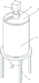
Fig. 1 is a perspective view of the present invention;
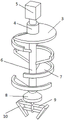
FIG. 2 is a schematic view of the internal structure of the present invention;
fig. 3 is a cross-sectional view of the present invention;
in the figure: 1-discharge bin frame, 2-discharge bin, 3-discharge bin cover, 4-coupler, 5-motor, 6-rotating shaft, 7-material speed reducing plate, 8-material baffle, 9-connecting rod and 10-scraping blade.
Detailed Description
Example 1
As shown in fig. 1 to 3, the device comprises a discharging bin frame 1, a discharging bin 2, a discharging bin cover 3, a coupling 4, a motor 5, a rotating shaft 6, a material speed reducing plate 7, a material baffle plate 8, a connecting rod 9 and a scraping blade 10; the discharging bin frame 1 is arranged on the lower side of the outer surface of the discharging bin 2; the discharging bin cover 3 is arranged at the top of the discharging bin 2; the coupler is arranged in the center of the upper surface of the discharging bin cover 3; the motor 5 is arranged above the coupling 4; the rotating shaft 6 is arranged below the coupling 6; the material speed reducing plate 7 is arranged in the discharging bin 2; the material baffle 8 is arranged at the tail end of the rotating shaft 6; the connecting rod 9 is arranged in the center of the bottom of the material baffle plate 8; the wiper blade 10 is mounted at the end of the connecting rod 9.
As a preferred technical scheme of the utility model, the material speed reducing plate 7 has four parts, is in the shape of a semi-cone, and is uniformly arranged in the discharging bin 2 from top to bottom; the scraping pieces 10 are two pieces and are arranged at the tail ends of two sides of the connecting rod 9, and the surfaces of the scraping pieces are attached to the conical bottom surface of the discharging bin 2.
The utility model discloses the theory of operation: pour the concrete material into go out feed bin 2, the material passes through four layers of material air brake 7 to slow speed downflow opens motor 5, drives rotation axis 6 and rotates, drives doctor-bar 10 through connecting rod 9 and rotates on going out 2 conical surfaces in feed bin, clears away remaining material, flows from going out 2 mouths in feed bin. The material that leaves along the seam can be blockked by material baffle 8, and the edgewise flows down, has reduced the material of discharge gate and has piled up, reduces pressure for can accomplish the ejection of compact more easily.
The circuit connections referred to herein are conventional and will be suggested to one skilled in the art by a limited number of attempts and are well within the broad art. The motor 5 is a stepping motor, the inner wall of the discharging bin 2 and the upper surface of the material speed reducing plate 7 are both smooth surfaces, and other parts can be machined or purchased in the market.
Components not described in detail herein are prior art.
Although the present invention has been described in detail with reference to the specific embodiments, the present invention is not limited to the above embodiments, and various changes can be made without departing from the spirit of the present invention within the knowledge range of those skilled in the art, and modifications or variations without creative efforts are still within the scope of the present invention.
Claims (2)
1. The utility model provides a concrete goes out feed bin convenient to ejection of compact which characterized in that: comprises a discharging bin frame (1), a discharging bin (2), a discharging bin cover (3), a coupler (4), a motor (5), a rotating shaft (6), a material speed reducing plate (7), a material baffle plate (8), a connecting rod (9) and a scraping blade (10); the discharging bin frame (1) is arranged on the lower side of the outer surface of the discharging bin (2); the discharging bin cover (3) is arranged at the top of the discharging bin (2); the coupler is arranged in the center of the upper surface of the discharging bin cover (3); the motor (5) is arranged above the coupling (4); the rotating shaft (6) is arranged below the coupler (4); the material speed reducing plate (7) is arranged in the discharging bin (2); the material baffle (8) is arranged at the tail end of the rotating shaft (6); the connecting rod (9) is arranged in the center of the bottom of the material baffle (8); the scraping blade (10) is arranged at the tail end of the connecting rod (9).
2. The concrete discharging bin convenient for discharging according to claim 1, characterized in that: the material speed reducing plates (7) are four in number, are in the shape of a semi-cone, and are uniformly arranged in the discharging bin (2) from top to bottom; the scraping pieces (10) are two pieces and are arranged at the tail ends of two sides of the connecting rod (9), and the surfaces of the scraping pieces are attached to the conical bottom surface of the discharging bin (2).
Priority Applications (1)
| Application Number | Priority Date | Filing Date | Title |
|---|---|---|---|
| CN202120685087.6U CN214525825U (en) | 2021-04-06 | 2021-04-06 | Concrete goes out feed bin convenient to ejection of compact |
Applications Claiming Priority (1)
| Application Number | Priority Date | Filing Date | Title |
|---|---|---|---|
| CN202120685087.6U CN214525825U (en) | 2021-04-06 | 2021-04-06 | Concrete goes out feed bin convenient to ejection of compact |
Publications (1)
| Publication Number | Publication Date |
|---|---|
| CN214525825U true CN214525825U (en) | 2021-10-29 |
Family
ID=78272050
Family Applications (1)
| Application Number | Title | Priority Date | Filing Date |
|---|---|---|---|
| CN202120685087.6U Active CN214525825U (en) | 2021-04-06 | 2021-04-06 | Concrete goes out feed bin convenient to ejection of compact |
Country Status (1)
| Country | Link |
|---|---|
| CN (1) | CN214525825U (en) |
-
2021
- 2021-04-06 CN CN202120685087.6U patent/CN214525825U/en active Active
Similar Documents
| Publication | Publication Date | Title |
|---|---|---|
| CN219076073U (en) | A high-efficiency cement slurry mixing device | |
| CN206855758U (en) | A kind of concrete for construction engineering mixer | |
| CN116690766A (en) | Pouring device for aerated brick pouring process | |
| CN221441470U (en) | A quick-detachable grouting device | |
| CN210732821U (en) | A pouring device for recycled concrete aggregate | |
| CN220428826U (en) | High-efficiency concrete mixing device | |
| CN218838174U (en) | A dry-mixed mortar anti-segregation storage tank | |
| CN219359812U (en) | A concrete mixing device for convenient discharging | |
| CN218138959U (en) | Filling slurry stirring device capable of continuously feeding and discharging | |
| CN116533384A (en) | Concrete filling device for building structure and application method thereof | |
| CN205086183U (en) | High -efficient stirring grouter | |
| CN211313411U (en) | An auxiliary funnel for pouring concrete | |
| CN219006506U (en) | Mixing device for concrete production | |
| CN211194470U (en) | A kind of concrete pouring blanking anti-separation device | |
| CN218905825U (en) | Low-carbon environment-friendly mortar stirring device | |
| CN211133784U (en) | Photovoltaic material mixing and stirring device | |
| CN218659814U (en) | Inter-pile mould pouring concrete pouring blanking hopper | |
| CN207711049U (en) | A kind of artificial quartz in lump blender | |
| CN208049816U (en) | A new type of mixer | |
| CN112060324A (en) | Concrete mixing device for engineering | |
| CN218132344U (en) | Polycarboxylate water reducing agent loading attachment | |
| CN221834619U (en) | Concrete pouring device | |
| CN221736616U (en) | A high efficiency mixing device | |
| CN215055414U (en) | Municipal administration building reinforced concrete pouring equipment | |
| CN219241371U (en) | Civil engineering watering device with guide function |
Legal Events
| Date | Code | Title | Description |
|---|---|---|---|
| GR01 | Patent grant | ||
| GR01 | Patent grant |