Electric automobile chassis trades electric installation
Technical Field
The utility model relates to an electric automobile chassis trades electric installation technical field, specifically is an electric automobile chassis trades electric installation.
Background
With the progress and development of society, the traditional energy is more and more close to exhaustion, so the development of new energy is imperative, and various novel energy such as nuclear energy, solar energy, combustible ice and the like are the trend of the development of future energy science and technology and become the source of future automobile power.
Many electric automobile chassis trade electric installation appears in the existing market, but most device is not good at height-adjusting device to and the not good risk that leads to the battery to drop easily of mounting fixture device, and prevent that the device that collapses that inclines is not good, leads to the crooked risk of bracing piece easily.
SUMMERY OF THE UTILITY MODEL
An object of the utility model is to provide an electric automobile chassis trades electric installation to it is not good to solve the high adjusting device who provides in the above-mentioned background art, and anchor clamps are fixed not good and support the not good problem of hardness.
In order to achieve the above object, the utility model provides a following technical scheme: the utility model provides an electric automobile chassis trades electric installation, includes base, rotary rod and slip case, be provided with a support section of thick bamboo in the middle of the top of base, and the top of a support section of thick bamboo installs the bracing piece to the top of bracing piece is connected with the backup pad, the rotary rod sets up in the top both sides of base, and the top of rotary rod installs the connecting rod, the adjustable ring is installed to two sides of connecting rod, and the intermediate junction of adjustable ring has the screw rod to the pull rod is installed in the outside of adjustable ring, the slip case sets up in the top of backup pad, and installs the handle in the middle of the outside of slip case, and the outside of handle installs rotatory tooth, the rotatory tooth outside is connected with the draw runner, and the draw runner top is provided with the saddle to spacing section of thick bamboo is installed in the outside of draw runner, the gag lever is installed in spacing section of thick bamboo left side, and the outside of gag lever is provided with the adapter sleeve.
Preferably, the base is tightly attached to the supporting cylinder, and the supporting cylinder and the supporting rod are in a sliding structure.
Preferably, a rotating structure is formed between the rotating rod and the pull rod through a screw, and the screw is connected with the connecting rod in a nested manner.
Preferably, the connecting rod is in threaded connection with the adjusting ring, and the adjusting ring is symmetrically arranged around the central axis of the connecting rod.
Preferably, the handle is connected with the rotating teeth in a nested mode, and the rotating teeth are connected with the sliding strip in a meshed mode.
Preferably, the sliding strip is connected with the limiting cylinder in a nested mode, and the sliding strip is connected with the supporting table in a clamping mode.
Preferably, sliding connection is adopted between the limiting cylinder and the limiting rod, and threaded connection is adopted between the limiting rod and the fastening sleeve.
Compared with the prior art, the beneficial effects of the utility model are that:
1. according to the electric automobile chassis battery replacing device, the connecting rod is effectively driven to move on the screw rod by rotating the screw rod, the rotating rod on the connecting rod and the pull rod can be driven to effectively rotate by moving the screw rod, the pull rod can move upwards to stably support the supporting plate, and the function of adjusting the height of the supporting plate can be realized;
2. according to the electric automobile chassis battery replacing device, the handle is rotated to drive the rotating teeth to effectively rotate, the rotating teeth can drive the lower sliding strip and the upper sliding strip to effectively slide, and the effect of driving the sliding strip to stretch and retract by rotating the rotating teeth can be achieved;
3. this electric automobile chassis trades electric installation is connected with spacing section of thick bamboo and gag lever post through the outside at the draw runner, makes a spacing section of thick bamboo effectively slide in the gag lever post is inboard, can realize the effect of a spacing section of thick bamboo in the inboard slide adjusting of gag lever post steadily supporting the draw runner to and carry out the effect of effectively injecing to a spacing section of thick bamboo and gag lever post through rotating the adapter sleeve on a spacing section of thick bamboo.
Drawings
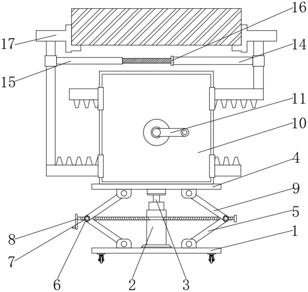
FIG. 1 is a schematic front view of the present invention;
FIG. 2 is a schematic view of the front cross-sectional structure of the sliding box of the present invention;
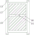
FIG. 3 is a right side view of the base of the present invention;
fig. 4 is a schematic view of the top-view cross-sectional structure of the pallet of the present invention.
In the figure: 1. a base; 2. a support cylinder; 3. a support bar; 4. a support plate; 5. rotating the rod; 6. a connecting rod; 7. an adjusting ring; 8. a screw; 9. a pull rod; 10. a slide box; 11. a handle; 12. rotating the teeth; 13. a slide bar; 14. a limiting cylinder; 15. a limiting rod; 16. fastening sleeves; 17. a saddle.
Detailed Description
The technical solutions in the embodiments of the present invention will be described clearly and completely with reference to the accompanying drawings in the embodiments of the present invention, and it is obvious that the described embodiments are only some embodiments of the present invention, not all embodiments. Based on the embodiments in the present invention, all other embodiments obtained by a person skilled in the art without creative work belong to the protection scope of the present invention.
Referring to fig. 1-4, the present invention provides a technical solution: a chassis battery replacing device for an electric automobile comprises a base 1, a supporting barrel 2, a supporting rod 3, a supporting plate 4, a rotary rod 5, a connecting rod 6, an adjusting ring 7, a screw 8, a pull rod 9, a sliding box 10, a handle 11, a rotary tooth 12, a slide bar 13, a limiting barrel 14, a limiting rod 15, a fastening sleeve 16 and a supporting platform 17, wherein the supporting barrel 2 is arranged in the middle of the top of the base 1, the supporting rod 3 is installed at the top of the supporting barrel 2, the supporting plate 4 is connected to the top of the supporting rod 3, the rotary rod 5 is arranged on two sides of the top of the base 1, the connecting rod 6 is installed at the top of the rotary rod 5, the adjusting rings 7 are installed on two sides of the connecting rod 6, the screw 8 is connected to the middle of the adjusting ring 7, the pull rod 9 is installed on the outer side of the adjusting ring 7, the sliding box 10 is arranged on the top of the supporting plate 4, the handle 11 is installed in the middle of the outer side of the sliding box 10, and the outside of handle 11 is installed rotatory tooth 12, and the outside of rotatory tooth 12 is connected with draw runner 13, and draw runner 13 top is provided with saddle 17 to spacing section of thick bamboo 14 is installed to the outside of draw runner 13, and gag lever post 15 is installed to spacing section of thick bamboo 14 left side, and the outside of gag lever post 15 is provided with adapter sleeve 16.
In the embodiment, the base 1 is tightly attached to the support cylinder 2, and the support cylinder 2 and the support rod 3 are in a sliding structure, so that the design ensures that the base 1 stably supports the support cylinder 2 and the support cylinder 2 effectively slides on the inner side of the support rod 3;
in the embodiment, the rotating structure is formed between the rotating rod 5 and the pull rod 9 through the screw 8, and the screw 8 is connected with the connecting rod 6 in a nested manner, so that the rotating structure is formed between the pull rod 9 and the rotating rod 5 through the screw 8 effectively, and the connecting rod 6 is driven to rotate effectively through the rotating screw 8;
in the embodiment, the connecting rod 6 is in threaded connection with the adjusting ring 7, and the adjusting ring 7 is symmetrically arranged about the axis of the connecting rod 6, so that the connecting rod 6 is effectively limited by the adjusting ring 7, and the connecting rod 6 can be effectively limited by rotating the adjusting ring 7;
in the embodiment, the handle 11 is connected with the rotating tooth 12 in a nested manner, and the rotating tooth 12 is connected with the sliding strip 13 in a meshed manner, so that the handle 11 is effectively connected with the rotating tooth 12, and the rotating tooth 12 is driven to effectively rotate by the rotating handle 11;
in the embodiment, the sliding strip 13 is connected with the limiting cylinder 14 in a nested manner, and the sliding strip 13 is connected with the supporting platform 17 in a clamping manner, so that the sliding strip 13 can effectively support the limiting cylinder 14 and the sliding strip 13 can stably support the supporting platform 17;
in this embodiment, the limiting cylinder 14 is slidably connected with the limiting rod 15, and the limiting rod 15 is threadedly connected with the fastening sleeve 16, so that the limiting cylinder 14 can effectively slide inside the limiting rod 15, and the limiting cylinder 14 can be limited by rotating the fastening sleeve 16.
The working principle is as follows: the electric automobile chassis battery replacing device is used in the process that firstly, the screw 8 is rotated to effectively drive the connecting rod 6 to move on the screw 8, the rotating rod 5 on the connecting rod 6 is driven to effectively rotate with the pull rod 9 by moving the screw 8, the pull rod 9 is enabled to move upwards to stably support the support plate 4, and the function of adjusting the height of the support plate 4 can be realized;
secondly, the handle 11 is rotated to enable the handle 11 to drive the rotating teeth 12 to effectively rotate, so that the lower sliding strip 13 and the upper sliding strip 13 can be effectively driven to slide by the rotating teeth 12, and the effect of driving the sliding strip 13 to stretch by rotating the rotating teeth 12 can be achieved;
the limiting cylinder 14 and the limiting rod 15 are connected to the outer side of the sliding strip 13, so that the limiting cylinder 14 effectively slides on the inner side of the limiting rod 15, the effect that the limiting cylinder 14 stably supports the sliding strip 13 in a sliding adjustment mode on the inner side of the limiting rod 15 can be achieved, and the effect that the limiting cylinder 14 and the limiting rod 15 are effectively limited by rotating the fastening sleeve 16 on the limiting cylinder 14 can be achieved.
Although embodiments of the present invention have been shown and described, it will be appreciated by those skilled in the art that changes, modifications, substitutions and alterations can be made in these embodiments without departing from the principles and spirit of the invention, the scope of which is defined in the appended claims and their equivalents.