CN214517445U - Manufacturing mold for instruments and meters - Google Patents
Manufacturing mold for instruments and meters Download PDFInfo
- Publication number
- CN214517445U CN214517445U CN202022015740.6U CN202022015740U CN214517445U CN 214517445 U CN214517445 U CN 214517445U CN 202022015740 U CN202022015740 U CN 202022015740U CN 214517445 U CN214517445 U CN 214517445U
- Authority
- CN
- China
- Prior art keywords
- pipe
- fixedly connected
- fan
- mould
- cooling
- Prior art date
- Legal status (The legal status is an assumption and is not a legal conclusion. Google has not performed a legal analysis and makes no representation as to the accuracy of the status listed.)
- Active
Links
- 238000004519 manufacturing process Methods 0.000 title claims description 19
- 238000001816 cooling Methods 0.000 claims abstract description 35
- XLYOFNOQVPJJNP-UHFFFAOYSA-N water Substances O XLYOFNOQVPJJNP-UHFFFAOYSA-N 0.000 claims description 13
- 239000007921 spray Substances 0.000 claims description 7
- RYGMFSIKBFXOCR-UHFFFAOYSA-N Copper Chemical compound [Cu] RYGMFSIKBFXOCR-UHFFFAOYSA-N 0.000 claims description 3
- 229910052802 copper Inorganic materials 0.000 claims description 3
- 239000010949 copper Substances 0.000 claims description 3
- 230000000694 effects Effects 0.000 abstract description 7
- 239000000498 cooling water Substances 0.000 description 2
- 230000017525 heat dissipation Effects 0.000 description 2
- 239000000463 material Substances 0.000 description 2
- 230000004075 alteration Effects 0.000 description 1
- 230000009286 beneficial effect Effects 0.000 description 1
- 238000010586 diagram Methods 0.000 description 1
- 238000002474 experimental method Methods 0.000 description 1
- 238000012986 modification Methods 0.000 description 1
- 230000004048 modification Effects 0.000 description 1
- 238000006467 substitution reaction Methods 0.000 description 1
Images


Landscapes
- Blow-Moulding Or Thermoforming Of Plastics Or The Like (AREA)
Abstract
The utility model discloses an instrument and meter is with making mould, which comprises a die body, the both sides of mould body all are provided with the fixed plate, the bottom fixedly connected with fixed block of fixed plate one side, the top fixedly connected with fan of fixed block, one side intercommunication of fan has the intake pipe, the opposite side intercommunication of fan has the outlet duct, the top and the equal fixedly connected with limiting plate in bottom of fixed plate one side, fixedly connected with shunt tubes between two limiting plates, one side intercommunication of shunt tubes has the shower nozzle, the one end intercommunication that the fan was kept away from to the outlet duct has the gas-supply pipe. The utility model discloses a cooperation of mould body, fixed plate, fixed block, fan, intake pipe, outlet duct, limiting plate, shunt tubes, shower nozzle, gas-supply pipe, cooling tube, inlet tube, solenoid valve and outlet pipe is used, and the cooling effect that can effectual improvement mould body makes mould rapid prototyping, has improved product quality.
Description
Technical Field
The utility model relates to a technical field is made to the mould, specifically is an instrument and meter is with making mould.
Background
In short, the mould is a tool for manufacturing a formed article, the tool is composed of various parts, different moulds are composed of different parts, the processing of the appearance of the article is realized mainly by changing the physical state of the formed material, the tool is called as an industrial mother, a special manufacturing mould is required when an instrument is manufactured, but the existing manufacturing mould has poor cooling effect, cannot enable the mould to be rapidly formed, and influences the product quality and the production efficiency.
SUMMERY OF THE UTILITY MODEL
An object of the utility model is to provide an instrument and meter is with making mould possesses quick refrigerated advantage, and it is relatively poor to have solved current manufacturing mould cooling effect, can not make mould rapid prototyping, influences product quality and production efficiency's problem.
In order to achieve the above object, the utility model provides a following technical scheme: a manufacturing mold for instruments and meters comprises a mold body, wherein fixed plates are arranged on two sides of the mold body, a fixed block is fixedly connected to the bottom of one side of each fixed plate, a fan is fixedly connected to the top of each fixed plate, an air inlet pipe is communicated with one side of the fan, an air outlet pipe is communicated with the other side of the fan, limiting plates are fixedly connected to the top and the bottom of one side of each fixed plate, a flow dividing pipe is fixedly connected between the two limiting plates, a spray head is communicated with one side of the flow dividing pipe, a gas pipe is communicated with one end, away from the fan, of the air outlet pipe, one end, away from the air outlet pipe, of the gas pipe penetrates through one side of the fixed plates and is communicated with the flow dividing pipe, a cooling pipe is fixedly connected to the inner cavity of the mold body, the left end of the cooling pipe is communicated with a water inlet pipe, the left end of the water inlet pipe penetrates through the left side of the mold body, and the surface of the water inlet pipe is communicated with a solenoid valve, the right end of the cooling pipe is communicated with a water outlet pipe.
Preferably, the bottom fixedly connected with fixing base of fan, the bottom of fixing base and the top fixed connection of fixed block.
Preferably, the number of the spray heads is twelve, and twelve spray heads are uniformly distributed on the two shunt pipes.
Preferably, the two sides of the cooling pipe are fixedly connected with limit blocks, and the limit blocks are fixedly connected in the inner cavity of the die body through bolts.
Preferably, the left end of the water inlet pipe is communicated with an external cold water tank, and the cooling pipe is made of a copper pipe.
Compared with the prior art, the beneficial effects of the utility model are as follows:
1. the utility model discloses a cooperation of mould body, fixed plate, fixed block, fan, intake pipe, outlet duct, limiting plate, shunt tubes, shower nozzle, gas-supply pipe, cooling tube, inlet tube, solenoid valve and outlet pipe is used, and the cooling effect that can effectual improvement mould body makes mould rapid prototyping, has improved product quality, and it is relatively poor to have solved current manufacturing mould cooling effect, can not make mould rapid prototyping, influences product quality and production efficiency's problem.
2. The utility model discloses a set up the fixing base, can be with the better fixing of fan on the fixed block, make the operation that the fan can be better, through setting up the shower nozzle, can make the more quick heat dissipation of mould body, through setting up the stopper, can make the better fixing of cooling tube in the mould body, through setting up the cold water groove, can make the more quick heat dissipation of inner chamber of mould body.
Drawings
FIG. 1 is a schematic structural view of the present invention;
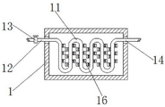
fig. 2 is a schematic top cross-sectional view of the die body of the present invention;
fig. 3 is the external structure diagram of the die body of the present invention.
In the figure: 1. a mold body; 2. a fixing plate; 3. a fixed block; 4. a fan; 5. an air inlet pipe; 6. an air outlet pipe; 7. a limiting plate; 8. a shunt tube; 9. a spray head; 10. a gas delivery pipe; 11. a cooling tube; 12. a water inlet pipe; 13. an electromagnetic valve; 14. a water outlet pipe; 15. a fixed seat; 16. and a limiting block.
Detailed Description
The technical solutions in the embodiments of the present invention will be described clearly and completely with reference to the accompanying drawings in the embodiments of the present invention, and it is obvious that the described embodiments are only some embodiments of the present invention, not all embodiments. Based on the embodiments in the present invention, all other embodiments obtained by a person skilled in the art without creative work belong to the protection scope of the present invention.
The components of the present invention are all standard components or components known to those skilled in the art, and the structure and principle thereof can be known by the technical manual or by the conventional experimental method.
Referring to fig. 1-3, a manufacturing mold for instruments and meters comprises a mold body 1, wherein two sides of the mold body 1 are respectively provided with a fixing plate 2, the bottom of one side of the fixing plate 2 is fixedly connected with a fixing block 3, the top of the fixing block 3 is fixedly connected with a fan 4, the bottom of the fan 4 is fixedly connected with a fixing seat 15, the bottom of the fixing seat 15 is fixedly connected with the top of the fixing block 3, the fan 4 can be better fixed on the fixing block 3 by arranging the fixing seat 15, so that the fan 4 can better operate, one side of the fan 4 is communicated with an air inlet pipe 5, the other side of the fan 4 is communicated with an air outlet pipe 6, the top and the bottom of one side of the fixing plate 2 are respectively fixedly connected with a limiting plate 7, a shunt pipe 8 is fixedly connected between the two limiting plates 7, one side of the shunt pipe 8 is communicated with a nozzle 9, the number of the nozzles 9 is twelve, and the twelve nozzles 9 are uniformly distributed on the two shunt pipes 8, through setting up the shower nozzle 9, can make the mould body 1 dispel the heat more fast, the one end that the outlet duct 6 keeps away from the fan 4 communicates with the gas-supply pipe 10, the one end that the gas-supply pipe 10 keeps away from the outlet duct 6 runs through to one side of the fixed plate 2 and communicates with shunt tubes 8, the inner chamber of the mould body 1 is fixedly connected with the cooling tube 11, both sides of the cooling tube 11 are fixedly connected with the stopper 16, the stopper 16 is fixedly connected in the inner chamber of the mould body 1 through the bolt, through setting up the stopper 16, can make the cooling tube 11 better fix in the mould body 1, the left end of the cooling tube 11 communicates with the inlet tube 12, the left end of the inlet tube 12 communicates with the outside cold water tank, the material of the cooling tube 11 is the copper pipe, through setting up the cold water tank, can make the inner chamber of the mould body 1 dispel the heat more fast, the left end of the inlet tube 12 runs through to the left side of the mould body 1, the surface of the inlet tube 12 communicates with the electromagnetic valve 13, the right-hand member intercommunication of cooling tube 11 has outlet pipe 14, through mould body 1, fixed plate 2, fixed block 3, fan 4, intake pipe 5, outlet duct 6, limiting plate 7, shunt tubes 8, shower nozzle 9, the gas-supply pipe 10, cooling tube 11, inlet tube 12, solenoid valve 13 and outlet pipe 14's cooperation is used, can effectual improvement mould body 1's cooling effect, make the mould rapid prototyping, the product quality has been improved, it is relatively poor to have solved current manufacturing mould cooling effect, can not make mould rapid prototyping, influence product quality and production efficiency's problem.
During the use, when using 1 manufacturing instrument of mould body, open solenoid valve 13 and fan 4, outside cooling water passes through inlet tube 12 and flows in cooling tube 11, the cooling water in the cooling tube 11 absorbs the heat in 1 mould body and discharges through outlet pipe 14, make the inside quick cooling of 1 mould body, fan 4 inhales outside wind through intake pipe 5, through outlet duct 6, gas-supply pipe 10, shunt tubes 8 and shower nozzle 9 are to 1 blowout of mould body, make 1 outside quick cooling of mould body, the cooling reaches the purpose of mould rapid prototyping through inside and outside quick cooling.
Although embodiments of the present invention have been shown and described, it will be appreciated by those skilled in the art that changes, modifications, substitutions and alterations can be made in these embodiments without departing from the principles and spirit of the invention, the scope of which is defined in the appended claims and their equivalents.
Claims (5)
1. The utility model provides an instrument is with making mould, includes mould body (1), its characterized in that: the mould is characterized in that fixing plates (2) are arranged on two sides of the mould body (1), a fixing block (3) is fixedly connected to the bottom of one side of the fixing plate (2), a fan (4) is fixedly connected to the top of the fixing block (3), an air inlet pipe (5) is communicated to one side of the fan (4), an air outlet pipe (6) is communicated to the other side of the fan (4), limiting plates (7) are fixedly connected to the top and the bottom of one side of the fixing plate (2), a shunt pipe (8) is fixedly connected between the two limiting plates (7), a spray head (9) is communicated to one side of the shunt pipe (8), an air pipe (10) is communicated to one end, away from the fan (4), of the air outlet pipe (6), one end, away from the air outlet pipe (6), of the air pipe (10) penetrates through one side of the fixing plate (2) and is communicated with the shunt pipe (8), and an inner cavity of the mould body (1) is fixedly connected with a cooling pipe (11), the left end intercommunication of cooling tube (11) has inlet tube (12), the left end of inlet tube (12) runs through to the left side of mould body (1), the surface intercommunication of inlet tube (12) has solenoid valve (13), the right-hand member intercommunication of cooling tube (11) has outlet pipe (14).
2. The manufacturing mold for an instrument and meter according to claim 1, wherein: the bottom fixedly connected with fixing base (15) of fan (4), the bottom of fixing base (15) and the top fixed connection of fixed block (3).
3. The manufacturing mold for an instrument and meter according to claim 1, wherein: the number of the spray heads (9) is twelve, and twelve spray heads (9) are uniformly distributed on the two shunt pipes (8).
4. The manufacturing mold for an instrument and meter according to claim 1, wherein: the cooling die is characterized in that two sides of the cooling pipe (11) are fixedly connected with limiting blocks (16), and the limiting blocks (16) are fixedly connected in an inner cavity of the die body (1) through bolts.
5. The manufacturing mold for an instrument and meter according to claim 1, wherein: the left end of the water inlet pipe (12) is communicated with an external cold water tank, and the cooling pipe (11) is made of a copper pipe.
Priority Applications (1)
| Application Number | Priority Date | Filing Date | Title |
|---|---|---|---|
| CN202022015740.6U CN214517445U (en) | 2020-09-15 | 2020-09-15 | Manufacturing mold for instruments and meters |
Applications Claiming Priority (1)
| Application Number | Priority Date | Filing Date | Title |
|---|---|---|---|
| CN202022015740.6U CN214517445U (en) | 2020-09-15 | 2020-09-15 | Manufacturing mold for instruments and meters |
Publications (1)
| Publication Number | Publication Date |
|---|---|
| CN214517445U true CN214517445U (en) | 2021-10-29 |
Family
ID=78229317
Family Applications (1)
| Application Number | Title | Priority Date | Filing Date |
|---|---|---|---|
| CN202022015740.6U Active CN214517445U (en) | 2020-09-15 | 2020-09-15 | Manufacturing mold for instruments and meters |
Country Status (1)
| Country | Link |
|---|---|
| CN (1) | CN214517445U (en) |
-
2020
- 2020-09-15 CN CN202022015740.6U patent/CN214517445U/en active Active
Similar Documents
| Publication | Publication Date | Title |
|---|---|---|
| CN206217109U (en) | A 3D-printed umbrella-shaped conformal cooling waterway mold that improves product surface quality | |
| CN211389927U (en) | A mold cooling water circuit | |
| CN105171976A (en) | Dry-type cooling shaping mold for wide sheet | |
| CN214820644U (en) | Spiral water channel cooling mechanism of injection mold | |
| CN205905305U (en) | High -frequency vibration automobile handle's rapid forming mould | |
| CN211135216U (en) | Intramode water spraying thermal forming die | |
| CN201442337U (en) | A cooling and shaping water tank for profile extrusion | |
| CN205522399U (en) | Pre -setting plastics tubular product mould | |
| CN204935976U (en) | Wide plate dry calibration stock mould | |
| CN215849498U (en) | Pagoda-shaped injection mold insert 3D printing is along with shape waterway structure | |
| CN212888788U (en) | Injection mold fountain waterway structure | |
| CN204977390U (en) | Pipe cooling device | |
| CN214188236U (en) | Injection mold for producing telescopic curtain plastic part of commercial vehicle | |
| CN219486641U (en) | Carbon fiber tube material pultrusion die | |
| CN207172675U (en) | A kind of profile-followed waterway structure of injection molding pipe part joint class mould | |
| CN224210418U (en) | Mould structure for small nozzle eccentric thin wall and climbing injection molding process | |
| CN212422034U (en) | Mold device with quick cooling structure | |
| CN209454121U (en) | A kind of polypropylene bellows plug die and the corrugated pipe forming head containing the plug die | |
| CN206455160U (en) | A kind of cooling structure of bus-bar mould | |
| CN216068426U (en) | 3D prints high-strength aluminum alloy mould | |
| CN219648652U (en) | Primary cooling device for horizontal continuous casting of copper pipe billets | |
| CN207156343U (en) | A kind of bloom is exempted to spray grill forming die | |
| CN222290928U (en) | Plastic mould | |
| CN206579107U (en) | 3D printing mold | |
| CN219405023U (en) | Quick cooling die |
Legal Events
| Date | Code | Title | Description |
|---|---|---|---|
| GR01 | Patent grant | ||
| GR01 | Patent grant |