CN214516662U - Automatic dust falling recovery device in dust-proof box - Google Patents
Automatic dust falling recovery device in dust-proof box Download PDFInfo
- Publication number
- CN214516662U CN214516662U CN202120938227.6U CN202120938227U CN214516662U CN 214516662 U CN214516662 U CN 214516662U CN 202120938227 U CN202120938227 U CN 202120938227U CN 214516662 U CN214516662 U CN 214516662U
- Authority
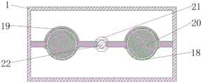
- CN
- China
- Prior art keywords
- dust
- box
- bevel gear
- sleeve
- block
- Prior art date
- Legal status (The legal status is an assumption and is not a legal conclusion. Google has not performed a legal analysis and makes no representation as to the accuracy of the status listed.)
- Expired - Fee Related
Links
Images



Landscapes
- Cleaning In General (AREA)
Abstract
The utility model relates to the technical field of dust treatment equipment, and discloses an automatic dust-falling recovery device in a dust-proof box, which comprises a box body, wherein a driving shaft is rotatably arranged at the top of an inner cavity of an adjusting box, a sleeve is slidably arranged on the outer surface of the driving shaft through a sliding strip, two ends of the sleeve are fixedly provided with a bevel gear, the automatic dust-falling recovery device in the dust-proof box is characterized in that the driving shaft is matched with the bevel gear and the bevel gear to drive a lead screw to rotate forwards, the lead screw is matched with a T-shaped dust pushing block through a sliding block to push dust to the right side and is matched with a negative pressure dust suction device to suck the dust away, when an electric telescopic rod drives a U-shaped movable block to move downwards, the concave ring sleeve is matched with a connecting block to drive a concave ring sleeve to move upwards, the concave ring sleeve drives the bevel gear below to be meshed with the bevel gear and drives the lead screw to rotate backwards, namely, the T-shaped dust pushing block is driven to push the dust to the left side to be sucked out by the negative pressure dust suction device, the dust at the bottom of the dustproof box is convenient to clean.
Description
Technical Field
The utility model relates to a dust treatment facility technical field specifically is an automatic recovery unit of dust proof incasement portion dust fall.
Background
The dust-proof box is a box body for preventing dust from rising, when a user carves wood, stone or other materials, the user needs to use a knife, a chisel, a round chisel, a cone, a polishing device and the like, so that various kinds of dust and rudimental miasma cannot be generated, and the dust-proof box is indispensable for the health of the user and the family.
When the existing dust-proof box is used, dust easily falls to the bottom, and is inconvenient to automatically recover and treat, the dust accumulation in the dust-proof box is more and easily influences the operation of users, the airtight effect of the dust-proof box is poor, and the dust is easily raised out from an operation opening to influence human health.
SUMMERY OF THE UTILITY MODEL
Technical problem to be solved
The utility model provides a not enough to prior art, the utility model provides an automatic recovery unit of dust proof incasement portion dust that falls, possess and to carry out automatic clearance collection to the dust that falls to the bottom, it is more convenient to the clearance of dust proof bottom of the case portion dust, the problem of the more user operation of influence of dust proof incasement portion dust accumulation has been avoided, the airtight effect of dust proof case has been improved, advantages such as dust is raised out from the operation mouth have effectively been prevented, the bottom has been solved the dust of dust proof incasement portion and has fallen to the bottom easily, inconvenient automatic recovery processing that carries on, the more easy operation that influences the user of dust proof incasement portion dust accumulation, the airtight effect of dust proof case is not good, the dust is raised out from the operation mouth easily, the problem of influence has been caused to the health.
(II) technical scheme
In order to solve the technical problem, the utility model provides a following technical scheme: an automatic dust falling recovery device in a dust-proof box comprises a box body, wherein an adjusting box is fixedly installed on the left side of the box body, a negative pressure dust suction device is fixedly installed on the back surface of an inner cavity of the box body and on two sides of the inner cavity of the box body, baffles are fixedly installed on two sides of the top of the inner cavity of the box body, a base is fixedly installed at the bottom of the inner cavity of the box body, a driving shaft is rotatably installed at the top of the inner cavity of the adjusting box, a sleeve is slidably installed on the outer surface of the driving shaft through a sliding strip, a first bevel gear is fixedly installed at two ends of the sleeve, a first lead screw is rotatably installed on the right side of the inner cavity of the base, the left end of the first lead screw sequentially penetrates through the base and the adjusting box and extends into the adjusting box, a second bevel gear is fixedly installed on the outer surface of the first lead screw, and the outer surfaces of the two first bevel gears are meshed with the outer surface of the second bevel gear, telescopic surface rotation installs concave type ring cover, the positive both sides of regulating box inner chamber all rotate through the fixed axle and install the connecting block, two one side that the connecting block is relative all rotates with the both sides of concave type ring cover to be connected, the equal fixed mounting in both sides of regulating box inner chamber bottom has electric telescopic handle, electric telescopic handle's top fixed mounting has U type movable block, the both sides of U type movable block internal surface all rotate with one side that two connecting blocks kept away from each other and are connected, the right-hand screw thread that the surface of a lead screw just is located No. two bevel gears installs the slider, the top fixed mounting of slider has T type to push away the dirt piece, the dust groove has been seted up at the top of base, the surface that the dirt piece was pushed away to T type and the interior surface sliding connection who leads the dirt groove.
Preferably, the two sides of the front surface of the inner cavity of the box body are fixedly provided with flexible connection dust covers, and the outer surfaces of the two flexible connection dust covers are fixedly provided with driving blocks.
Preferably, the operation openings are formed in the two sides of the front face of the box body, and the threaded sleeves are rotatably installed on the front face of the box body.
Preferably, both ends of the second screw rod penetrate through the threaded sleeve and extend to the outside of the threaded sleeve.
Preferably, the rear end of the thread sleeve penetrates through the box body and extends into the box body, and a second screw rod is mounted on the inner thread of the thread sleeve.
Preferably, a fixed block is fixedly installed between the two driving blocks, and the inner surface of the fixed block is fixedly connected with the outer surface of the second screw rod.
(III) advantageous effects
Compared with the prior art, the utility model provides an automatic recovery unit of dust proof incasement portion dust fall possesses following beneficial effect: the automatic dust-falling recovery device in the dust-proof box can drive the driving block to move forwards by rotating the threaded sleeve to match with the second lead screw, the driving block drives the flexible connection dust-proof cover to contract inwards, so that the flexible connection dust-proof cover is attached to the arm of a user, dust can be prevented from being raised out through the operation port, the first lead screw is driven to rotate forwards by the driving shaft matching with the sleeve, the first bevel gear and the second bevel gear, the first lead screw pushes the dust to the right side by the slide block matching with the T-shaped dust-pushing block and sucks the dust away by the negative pressure dust-collecting device matching with the slide block and the T-shaped dust-pushing block, the concave ring sleeve is driven to move upwards by the connecting block and the fixed shaft matching with the U-shaped movable block when the electric telescopic rod drives the U-shaped movable block to move downwards, the concave ring sleeve drives the first bevel gear and the second bevel gear to mesh and drive the first lead screw to rotate backwards by the sleeve, and the last lead screw drives the T-shaped dust-pushing block to push the left side to be sucked out by the negative pressure dust-collecting device, the operation is repeated to finish the treatment of the dust at the bottom of the box body.
1. The automatic dust falling recovery device in the dust-proof box drives the first screw rod to rotate forwards through the matching of the driving shaft and the sleeve, the first bevel gear and the second bevel gear, the first screw rod pushes dust to the right side through the matching of the sliding block and the T-shaped dust pushing block and sucks the dust through the matching of the sliding block and the negative pressure dust suction device, when the electric telescopic rod drives the U-shaped movable block to move downwards, the concave ring sleeve drives the concave ring sleeve to move upwards through the matching of the connecting block and the fixed shaft, the first bevel gear below the concave ring sleeve is driven by the sleeve to be meshed with the second bevel gear and drives the first screw rod to rotate backwards, the last screw rod drives the T-shaped dust pushing block to push the dust to the left side to be sucked out by the negative pressure dust suction device, the dust at the bottom of the box body can be treated by repeating the above operations, the purpose of automatically cleaning and collecting the dust falling to the bottom in the dust-proof box is realized, and the problem of inconvenient cleaning of the dust at the bottom of the dust-proof box is solved, the problem that the dust accumulation in the dust-proof box is more to influence the operation of users is avoided.
2. This automatic recovery unit of dust prevention incasement portion dust fall drives the drive block through rotating No. two lead screws of thread bush cooperation and moving forward, the drive block drives the inside shrink of flexible coupling dust cover, and then makes the laminating of flexible coupling dust cover and user's arm, can prevent that the dust from raising out through the operation mouth, has improved the airtight effect of dust prevention case, avoided user when using the dust prevention case, the problem that the dust raised out from the operation mouth, avoided the dust to cause the problem of influence to human health.
Drawings
Fig. 1 is a front view of the internal structure of the present invention in longitudinal section.
Fig. 2 is a front view of the inner structure of the adjusting box and the base of the present invention.
Fig. 3 is a perspective view of the external structure of the present invention.
Fig. 4 is a rear longitudinal sectional view of the internal structure of the present invention.
Fig. 5 is a side view of the external structure of the flexible connection dust cover of the present invention.
In the figure: 1. a box body; 2. an adjusting box; 3. a negative pressure dust suction device; 4. a baffle plate; 5. a base; 6. a drive shaft; 7. a sleeve; 8. a first bevel gear; 9. a first screw rod; 10. a second bevel gear; 11. a concave ring sleeve; 12. connecting blocks; 13. an electric telescopic rod; 14. a U-shaped movable block; 15. a slider; 16. a T-shaped dust pushing block; 17. a dust guide groove; 18. a flexible connection dust cover; 19. a drive block; 20. an operation port; 21. a threaded sleeve; 22. and a second screw rod.
Detailed Description
The technical solutions in the embodiments of the present invention will be described clearly and completely with reference to the accompanying drawings in the embodiments of the present invention, and it is obvious that the described embodiments are only some embodiments of the present invention, not all embodiments. Based on the embodiments in the present invention, all other embodiments obtained by a person skilled in the art without creative work belong to the protection scope of the present invention.
Referring to fig. 1-5, an automatic dust-collecting device for dust falling in a dust-proof box comprises a box body 1, an adjusting box 2 is fixedly arranged on the left side of the box body 1, a negative pressure dust-collecting device 3 is fixedly arranged on the back surface of an inner cavity of the box body 1 and on both sides of the inner cavity, a baffle 4 is fixedly arranged on both sides of the top of the inner cavity of the box body 1, a base 5 is fixedly arranged on the bottom of the inner cavity of the box body 1, a driving shaft 6 is rotatably arranged on the top of the inner cavity of the adjusting box 2, a sleeve 7 is slidably arranged on the outer surface of the driving shaft 6 through a sliding strip, a first bevel gear 8 is fixedly arranged on both ends of the sleeve 7, a first lead screw 9 is rotatably arranged on the right side of the inner cavity of the base 5, the left end of the first lead screw 9 sequentially penetrates through the base 5 and the adjusting box 2 and extends to the inside of the adjusting box 2, a second bevel gear 10 is fixedly arranged on the outer surface of the first lead screw 9, and the outer surfaces of the two first bevel gears 8 are engaged with the outer surface of the second bevel gear 10, a concave ring sleeve 11 is rotatably arranged on the outer surface of the sleeve 7, connecting blocks 12 are rotatably arranged on the two positive sides of the inner cavity of the adjusting box 2 through fixed shafts, one opposite sides of the two connecting blocks 12 are rotatably connected with the two sides of the concave ring sleeve 11, electric telescopic rods 13 are fixedly arranged on the two sides of the bottom of the inner cavity of the adjusting box 2, a U-shaped movable block 14 is fixedly arranged at the top end of each electric telescopic rod 13, the two sides of the inner surface of each U-shaped movable block 14 are rotatably connected with the mutually far side of the two connecting blocks 12, a sliding block 15 is arranged on the outer surface of the first screw rod 9 and positioned on the right thread of the second bevel gear 10, a T-shaped dust pushing block 16 is fixedly arranged at the top of the sliding block 15, a dust guide groove 17 is formed in the top of the base 5, the outer surface of the T-shaped dust pushing block 16 is slidably connected with the inner surface of the dust guide groove 17, and soft connection dust covers 18 are fixedly arranged on the two positive sides of the inner cavity of the box body 1, the equal fixed mounting in surface of two flexible coupling dust covers 18 has drive block 19, operation mouth 20 has all been seted up to the positive both sides of box 1, the front of box 1 is rotated and is installed thread bush 21, the rear end of thread bush 21 runs through box 1 and extends to the inside of box 1, No. two lead screws 22 are installed to the internal thread of thread bush 21, No. two lead screws 22's both ends all run through thread bush 21 and extend to the outside of thread bush 21, fixed mounting has the fixed block between two drive blocks 19, and the internal surface of fixed block and No. two lead screws 22's external fixed connection.
The working principle is as follows: firstly, a worker drives a driving block 19 to move forwards by rotating a threaded sleeve 21 and matching with a second lead screw 22, the driving block 19 drives a flexible connection dust cover 18 to shrink in the forward movement process, the flexible connection dust cover 18 is attached to the arm of a user, dust can be prevented from being ejected out through an operation port 20, an external driving device drives a driving shaft 6 to rotate, the driving shaft 6 drives a first lead screw 9 to rotate forwards by matching with a first bevel gear 8 and a second bevel gear 10 above a sleeve 7, the first lead screw 9 pushes dust in a dust guide groove 17 to the right side of an inner cavity of a box body 1 by matching with a T-shaped dust pushing block 16 through a sliding block 15 in the forward rotation process and sucks the dust by matching with a baffle 4 on the right side and a negative pressure dust suction device 3, when an electric telescopic rod 13 drives a U-shaped movable block 14 to move downwards, the concave ring sleeve 11 is driven by matching with a connecting block 12 and a fixed shaft to drive a concave ring sleeve 11 to move upwards, the concave ring 11 drives the first bevel gear 8 below the second bevel gear 10 to mesh and drives the first bevel gear 10 to drive the first bevel gear 10 through the first bevel gear 8 through the sleeve 7 The screw rod 9 rotates reversely, the last screw rod 9 drives the T-shaped dust pushing block 16 to push dust to the left side and suck the dust out of the negative pressure dust suction device 3, and the dust at the bottom of the box body 1 can be treated by repeating the operation.
To sum up, the automatic dust-falling recovery device in the dust-proof box can drive the driving block 19 to move forward by rotating the threaded sleeve 21 and matching with the second lead screw 22, the driving block 19 drives the flexible connection dust-proof cover 18 to contract inward, so that the flexible connection dust-proof cover 18 is attached to the arm of a user, thereby preventing dust from being raised out through the operation port 20, the first lead screw 9 is driven to rotate forward by matching with the sleeve 7, the first bevel gear 8 and the second bevel gear 10 through the driving shaft 6, the first lead screw 9 pushes dust to the right side by matching with the T-shaped dust pushing block 16 through the sliding block 15 and sucks the dust away by matching with the negative pressure dust suction device 3, when the electric telescopic rod 13 drives the U-shaped movable block 14 to move downward, the concave ring sleeve 11 is driven to move upward by matching with the connecting block 12 and the fixed shaft, the concave ring sleeve 11 drives the first bevel gear 8 below to be meshed with the second bevel gear 10 through the sleeve 7 and drives the first lead screw 9 to rotate backward, and the last screw rod 9 drives the T-shaped dust pushing block 16 to push the dust to the left side to be sucked out by the negative pressure dust suction device 3, and the dust at the bottom of the box body 1 can be treated by repeating the operation.
Although embodiments of the present invention have been shown and described, it will be appreciated by those skilled in the art that changes, modifications, substitutions and alterations can be made in these embodiments without departing from the principles and spirit of the invention, the scope of which is defined in the appended claims and their equivalents.
Claims (6)
1. The utility model provides an inside automatic recovery unit of dirt that falls of dust-protection box, includes box (1), the left side fixed mounting of box (1) has regulating box (2), the equal fixed mounting in both sides of the back of box (1) inner chamber and inner chamber has negative pressure dust extraction (3), its characterized in that: the two sides of the top of the inner cavity of the box body (1) are fixedly provided with baffles (4), the bottom of the inner cavity of the box body (1) is fixedly provided with a base (5), the top of the inner cavity of the adjusting box (2) is rotatably provided with a driving shaft (6), the outer surface of the driving shaft (6) is provided with a sleeve (7) in a sliding manner through a sliding strip, two ends of the sleeve (7) are fixedly provided with a first bevel gear (8), the right side of the inner cavity of the base (5) is rotatably provided with a first lead screw (9), the left end of the first lead screw (9) sequentially penetrates through the base (5) and the adjusting box (2) and extends into the adjusting box (2), the outer surface of the first lead screw (9) is fixedly provided with a second bevel gear (10), the outer surfaces of the two first bevel gears (8) are respectively meshed with the outer surface of the second bevel gear (10), and the outer surface of the sleeve (7) is rotatably provided with a concave ring sleeve (11), connecting blocks (12) are rotatably arranged on two sides of the front surface of the inner cavity of the adjusting box (2) through fixed shafts, one opposite side of each of the two connecting blocks (12) is rotatably connected with two sides of the concave ring sleeve (11), both sides of the bottom of the inner cavity of the adjusting box (2) are fixedly provided with electric telescopic rods (13), the top end of the electric telescopic rod (13) is fixedly provided with a U-shaped movable block (14), both sides of the inner surface of the U-shaped movable block (14) are rotatably connected with one side of the two connecting blocks (12) which is far away from each other, a sliding block (15) is arranged on the outer surface of the first screw rod (9) and positioned on the right thread of the second bevel gear (10), a T-shaped dust pushing block (16) is fixedly arranged at the top of the sliding block (15), a dust guiding groove (17) is arranged at the top of the base (5), the outer surface of the T-shaped dust pushing block (16) is connected with the inner surface of the dust guide groove (17) in a sliding manner.
2. The automatic dust falling recovery device in the dust-proof box according to claim 1, characterized in that: the flexible connection dustproof covers (18) are fixedly mounted on the two sides of the front surface of the inner cavity of the box body (1), and the driving blocks (19) are fixedly mounted on the outer surfaces of the two flexible connection dustproof covers (18).
3. The automatic dust falling recovery device in the dust-proof box according to claim 1, characterized in that: operation openings (20) are formed in the two sides of the front face of the box body (1), and a threaded sleeve (21) is rotatably mounted on the front face of the box body (1).
4. The automatic dust-fall recycling device in the dust-proof box according to claim 3, characterized in that: the rear end of the thread bush (21) penetrates through the box body (1) and extends to the inside of the box body (1), and a second screw rod (22) is installed on the internal thread of the thread bush (21).
5. The automatic dust-fall recycling device in the dust-proof box as claimed in claim 4, wherein: two ends of the second screw rod (22) penetrate through the threaded sleeve (21) and extend to the outside of the threaded sleeve (21).
6. The automatic dust falling recovery device in the dust-proof box according to claim 2, characterized in that: a fixed block is fixedly arranged between the two driving blocks (19), and the inner surface of the fixed block is fixedly connected with the outer surface of the second screw rod (22).
Priority Applications (1)
| Application Number | Priority Date | Filing Date | Title |
|---|---|---|---|
| CN202120938227.6U CN214516662U (en) | 2021-05-06 | 2021-05-06 | Automatic dust falling recovery device in dust-proof box |
Applications Claiming Priority (1)
| Application Number | Priority Date | Filing Date | Title |
|---|---|---|---|
| CN202120938227.6U CN214516662U (en) | 2021-05-06 | 2021-05-06 | Automatic dust falling recovery device in dust-proof box |
Publications (1)
| Publication Number | Publication Date |
|---|---|
| CN214516662U true CN214516662U (en) | 2021-10-29 |
Family
ID=78276260
Family Applications (1)
| Application Number | Title | Priority Date | Filing Date |
|---|---|---|---|
| CN202120938227.6U Expired - Fee Related CN214516662U (en) | 2021-05-06 | 2021-05-06 | Automatic dust falling recovery device in dust-proof box |
Country Status (1)
| Country | Link |
|---|---|
| CN (1) | CN214516662U (en) |
Cited By (1)
| Publication number | Priority date | Publication date | Assignee | Title |
|---|---|---|---|---|
| CN116510663A (en) * | 2023-05-06 | 2023-08-01 | 山西沁新能源集团股份有限公司 | Mixing stirring device for preparing ultralow-ash-content framework coke |
-
2021
- 2021-05-06 CN CN202120938227.6U patent/CN214516662U/en not_active Expired - Fee Related
Cited By (1)
| Publication number | Priority date | Publication date | Assignee | Title |
|---|---|---|---|---|
| CN116510663A (en) * | 2023-05-06 | 2023-08-01 | 山西沁新能源集团股份有限公司 | Mixing stirring device for preparing ultralow-ash-content framework coke |
Similar Documents
| Publication | Publication Date | Title |
|---|---|---|
| CN211891234U (en) | Board cutting device for furniture processing | |
| CN111015357A (en) | Cutting fluid collecting and filtering device for machine tool | |
| CN215201179U (en) | Outer wall grinding device is used in optical lens piece processing | |
| CN214419059U (en) | Diamond chain saw with dustproof function | |
| CN216811610U (en) | Hole cleaning device for drilling in building engineering construction | |
| CN213135818U (en) | Workstation is used in machining with clearance function | |
| CN113334833B (en) | A piece compaction device for gear precision finishing | |
| CN212346416U (en) | Sweeping device and sweeping robot | |
| CN115635404A (en) | Jack base surface frock of polishing | |
| CN219166279U (en) | Electric desktop dust collector | |
| CN222000890U (en) | Collecting device for building decoration waste | |
| CN221472712U (en) | Automatic slag extractor for hollow glass | |
| CN217476316U (en) | Large-size silicon wafer wire return cutting device with protection function | |
| CN216757314U (en) | Clean structure of press for forging | |
| CN220408020U (en) | Automatic cleaning device after processing precision parts | |
| CN217993021U (en) | A perforating device for kitchen guarding's construction | |
| CN214600960U (en) | Gear deburring device | |
| CN217648950U (en) | Artificial tooth 3D printing apparatus with cleaning function | |
| CN206612386U (en) | A kind of archives dust removal brush | |
| CN222537132U (en) | Wall grinding device for architectural decoration | |
| CN214560869U (en) | Robot for assembly line installation | |
| CN221604161U (en) | Cleaning device for grinding machine | |
| CN218103704U (en) | Multifunctional electric automation control console convenient to clean | |
| CN213967191U (en) | Tubular centrifuge cleaning device | |
| CN218710584U (en) | Brushing device of microfiber leather buffing machine |
Legal Events
| Date | Code | Title | Description |
|---|---|---|---|
| GR01 | Patent grant | ||
| GR01 | Patent grant | ||
| CF01 | Termination of patent right due to non-payment of annual fee |
Granted publication date: 20211029 |
|
| CF01 | Termination of patent right due to non-payment of annual fee |