Zero-discharge treatment device for coking wastewater
Technical Field
The utility model relates to a waste water treatment technical field, concretely relates to coking wastewater zero discharge processing apparatus.
Background
The wastewater treatment is to treat the wastewater by physical, chemical and biological methods, so that the wastewater is purified, the pollution is reduced, the wastewater is recycled and reused, and water resources are fully utilized.
The patent number is CN 212476314U's utility model discloses a coking wastewater zero release processing apparatus, including the cabinet body and positive and negative motor, the water inlet has been opened to cabinet body group left end upper side, be provided with the filter plate in the middle of the cabinet body, the delivery port has been seted up to cabinet body right-hand member downside, the delivery port right-hand member is provided with except that the oil tank, except that being provided with three group's deoiling boards in the oil tank, be provided with the valve on the delivery port, positive and negative motor is provided with in the middle of the cabinet body upper end, positive and negative motor's drive output end and electric telescopic handle transmission are connected.
The prior art has the following defects: a plurality of components and parts drive cleaning roller and cleaning brush move, and electric telescopic handle places in the waste water, can cause the harm to electric elements among the electric telescopic handle, influences subsequent result of use.
SUMMERY OF THE UTILITY MODEL
Therefore, the utility model provides a coking wastewater zero discharge treatment device, drive the actuating lever through positive and negative motor, lead screw and fourth bevel gear rotate, fourth bevel gear passes through third bevel gear, the connecting rod, second bevel gear and first bevel gear drive first bull stick and rotate, first bull stick passes through the gear, the cooperation of belt and two belt pulleys drives first bull stick and second bull stick and rotates, also drive the rotation of jar internal portion's location lagging simultaneously, location lagging drives the cleaning roller and rotates, the lead screw drives and receives the cleaning brush board on the thread plate to reciprocate, overall structure is simple, high efficiency, the cost is low.
In order to achieve the above object, the present invention provides the following technical solutions: a zero-discharge treatment device for coking wastewater comprises a tank body, wherein an opening is formed in the bottom of the tank body, a mounting plate is arranged in the opening, the bottom end of the mounting plate penetrates through the opening and extends to the outside of the opening, the mounting plate is detachably connected with the bottom of the tank body, a plurality of cleaning rollers are arranged in the tank body, a plurality of dirt storage openings are formed in the cleaning rollers, the cleaning rollers are uniformly arranged at intervals, positioning plates are fixedly arranged at the top and the bottom of each cleaning roller, a positioning sleeve plate is sleeved outside one end of each positioning plate, which is far away from the cleaning rollers, a positioning sleeve plate is movably connected with the top of the mounting plate and the top of an inner cavity of the tank body respectively through a rotating shaft, a first rotating rod is arranged at the top of the tank body, second rotating rods are arranged on the front side and the rear side of the first rotating rod, the bottom ends of the first rotating rod and the second rotating rods penetrate through the tank body and are fixedly connected with the positioning sleeve plates at the tops of the cleaning rollers respectively, the top of the first rotating rod is fixedly provided with a gear, the tops of the two second rotating rods are both fixedly provided with belt pulleys, a belt is arranged between the two belt pulleys, the gear is contacted with the inner wall of the belt, the two belt pulleys are connected through the belt, the bottom of the gear is provided with a first bevel gear, the first bevel gear is fixedly sleeved on the outer wall of the bottom of the first rotating rod, one side of the first bevel gear is provided with a second bevel gear, one side of the second bevel gear, away from the first bevel gear, is fixedly provided with a connecting rod, the outer part of the connecting rod is sleeved with a mounting plate, the connecting rod is connected with the inner wall of the mounting plate through a rotating shaft, the mounting plate is fixedly connected with the top of the tank body, one end of the connecting rod, away from the second bevel gear, is fixedly provided with a third bevel gear, one side of the third bevel gear is provided with a driving rod, the top of the driving rod is fixedly provided with a driving structure, and the driving rod is movably connected with the top of the tank body through a rotating shaft, the fixed fourth bevel gear that has cup jointed of actuating lever bottom outer wall, fourth bevel gear meshes with third bevel gear mutually, the fixed backup pad that is equipped with in one side that the cleaning roller was kept away from at the internal chamber top of jar, the spacing groove has been seted up to the backup pad bottom, the limiting groove inside is equipped with the lead screw, the lead screw top run through backup pad and jar body in proper order and with actuating lever bottom fixed connection, lead screw bottom outer wall threaded connection has the threading board, the threading board bottom extends to the backup pad bottom, the fixed L shape pole that is equipped with in one side that the cleaning roller was kept away from to the backup pad, the fixed cleaning brush board that is equipped with in one side that the backup pad was kept away from to the L shape pole, one side that the backup pad was kept away from to the cleaning brush board is equipped with the filter plate, the cleaning brush board contacts with the filter plate, filter plate and jar internal wall fixed connection.
Further, the fixed intercommunication in one side that the jar body is close to the cleaning roller has the inlet tube, the fixed intercommunication in jar body bottom has collecting pipe and outlet pipe, collecting pipe bottom threaded connection has the apron, the collecting pipe sets up in the one side that the filter plate is close to the backup pad, the outlet pipe sets up in the one side that the backup pad was kept away from to the filter plate, the fixed intercommunication in outlet pipe bottom has the rose box, the rose box front side is seted up and is equipped with a plurality of installing orificess, and a plurality of oil absorption cotton boards have all been pegged graft to a plurality of installing orificess inside, the oil absorption cotton board all extends to the rose box inside near the one end of installing orificess, the fixed intercommunication in rose box bottom has the L venturi tube.
Furthermore, the cross sections of the limiting groove and the thread plate are rectangular.
Furthermore, the cross sections of the positioning sleeve plate and the positioning plate are both rectangular.
Further, both sides are all fixed and are equipped with the fixed plate around the mounting panel bottom, fixed plate bottom threaded connection has the bolt, the bolt top runs through the fixed plate and extends to jar internal portion, the bolt is threaded connection with jar body.
Furthermore, four corners of the bottom of the tank body are fixedly provided with supporting legs.
Further, the driving structure is a positive and negative motor, and the positive and negative motor is fixedly arranged at the top of the driving rod.
Compared with the prior art, the utility model discloses following beneficial effect has:
1. the utility model discloses a positive and negative motor drives actuating lever, lead screw and fourth bevel gear and rotates, fourth bevel gear drives first bull stick through third bevel gear, connecting rod, second bevel gear and first bevel gear and rotates, first bull stick passes through the cooperation of gear, belt and two belt pulleys and drives first bull stick and second bull stick rotation, also drives the location lagging rotation of jar internal portion simultaneously, location lagging drives the cleaning roller and rotates, the lead screw drives the cleaning brush board on the screw thread board and reciprocates, overall structure is simple, high efficiency, the cost is low;
2. the utility model discloses a cooperation of mounting panel and bolt, the joint cooperation of location lagging and locating plate, the user of being convenient for installs and dismantles the cleaning roller.
Drawings
In order to more clearly illustrate the embodiments of the present invention or the technical solutions in the prior art, the drawings used in the description of the embodiments or the prior art will be briefly described below. It should be apparent that the drawings in the following description are merely exemplary, and that other embodiments can be derived from the drawings provided by those of ordinary skill in the art without inventive effort.
The structure, ratio, size and the like shown in the present specification are only used for matching with the content disclosed in the specification, so as to be known and read by people familiar with the technology, and are not used for limiting the limit conditions which can be implemented by the present invention, so that the present invention has no technical essential significance, and any structure modification, ratio relationship change or size adjustment should still fall within the scope which can be covered by the technical content disclosed by the present invention without affecting the efficacy and the achievable purpose of the present invention.
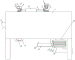
FIG. 1 is a front view of the overall structure provided by the present invention;
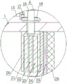
fig. 2 is a cross-sectional view of the overall structure provided by the present invention;
fig. 3 is an enlarged view of a portion a in fig. 2 according to the present invention;
FIG. 4 is a side sectional view of the cleaning rod, the positioning plate and the positioning sleeve plate provided by the present invention;
fig. 5 is a top view of the support plate, the screw rod and the thread plate provided by the present invention.
In the figure: 1 tank body, 2 through holes, 3 mounting plates, 4 cleaning rollers, 5 dirt storage holes, 6 positioning plates, 7 positioning sleeve plates, 8 first rotating rods, 9 second rotating rods, 10 gears, 11 belt pulleys, 12 belts, 13 first bevel gears, 14 second bevel gears, 15 connecting rods, 16 placement plates, 17 third bevel gears, 18 driving rods, 19 fourth bevel gears, 20 supporting plates, 21 limiting grooves, 22 screw rods, 23 threaded plates, 24L-shaped rods, 25 cleaning brush plates, 26 filter screen plates, 27 water inlet pipes, 28 collecting pipes, 29 water outlet pipes, 30 cover plates, 31 filter boxes, 32 mounting holes, 33 oil absorption cotton plates, 34L-shaped pipes, 35 fixing plates and 36 positive and negative motors.
Detailed Description
The present invention is described in terms of specific embodiments, and other advantages and benefits of the present invention will become apparent to those skilled in the art from the following disclosure. Based on the embodiments in the present invention, all other embodiments obtained by a person skilled in the art without creative work belong to the protection scope of the present invention.
Referring to the attached drawings 1-5 of the specification, the zero-emission treatment device for coking wastewater comprises a tank body 1, wherein the bottom of the tank body 1 is provided with a through hole 2, a mounting plate 3 is arranged inside the through hole 2, the bottom end of the mounting plate 3 penetrates through the through hole 2 and extends to the outside of the through hole 2, the mounting plate 3 is detachably connected with the bottom of the tank body 1, the tank body 1 is internally provided with a plurality of cleaning rollers 4, the cleaning rollers 4 are respectively provided with a plurality of dirt storage openings 5, the cleaning rollers 4 are uniformly arranged at intervals, the top and the bottom of each cleaning roller 4 are respectively and fixedly provided with a positioning plate 6, one end of each positioning plate 6, which is far away from the cleaning roller 4, is externally sleeved with a positioning sleeve plate 7, the positioning sleeve plates 7 at the top end and the bottom end of each cleaning roller 4 are respectively and movably connected with the top of the mounting plate 3 and the top of an inner cavity of the tank body 1 through rotating shafts, the top of the tank body 1 is provided with a first rotating rod 8, the front side and the rear side of the first rotating rod 8 are respectively provided with a second rotating rod 9, the bottom ends of the first rotating rod 8 and the second rotating rod 9 penetrate through the tank body 1 and are respectively fixedly connected with the positioning sleeve plates 7 at the tops of the cleaning rollers 4, the top end of the first rotating rod 8 is fixedly provided with a gear 10, the tops of the two second rotating rods 9 are respectively fixedly provided with a belt pulley 11, a belt 12 is arranged between the two belt pulleys 11, the gear 10 is in contact with the inner wall of the belt 12, the two belt pulleys 11 are connected through the belt 12, the bottom of the gear 10 is provided with a first bevel gear 13, the first bevel gear 13 is fixedly sleeved on the outer wall of the bottom end of the first rotating rod 8, one side of the first bevel gear 13 is provided with a second bevel gear 14, one side of the second bevel gear 14, which is far away from the first bevel gear 13, is fixedly provided with a connecting rod 15, the outer part of the connecting rod 15 is sleeved with a mounting plate 16, and the connecting rod 15 is connected with the inner wall of the mounting plate 16 through a rotating shaft, the placing plate 16 is fixedly connected with the top of the tank body 1, one end of the connecting rod 15, which is far away from the second bevel gear 14, is fixedly provided with a third bevel gear 17, one side of the third bevel gear 17 is provided with a driving rod 18, the top of the driving rod 18 is fixedly provided with a driving structure, the driving rod 18 is movably connected with the top of the tank body 1 through a rotating shaft, the outer wall of the bottom end of the driving rod 18 is fixedly connected with a fourth bevel gear 19, the fourth bevel gear 19 is meshed with the third bevel gear 17, one side of the top of the inner cavity of the tank body 1, which is far away from the cleaning roller 4, is fixedly provided with a supporting plate 20, the bottom of the supporting plate 20 is provided with a limiting groove 21, a lead screw 22 is arranged inside the limiting groove 21, the top end of the lead screw 22 sequentially penetrates through the supporting plate 20 and the tank body 1 and is fixedly connected with the bottom end of the driving rod 18, the outer wall of the bottom end of the lead screw 22 is in threaded connection with a thread plate 23, and the bottom end of the thread plate extends to the bottom of the supporting plate 20, an L-shaped rod 24 is fixedly arranged on one side, far away from the cleaning roller 4, of the supporting plate 20, a cleaning brush plate 25 is fixedly arranged on one side, far away from the supporting plate 20, of the L-shaped rod 24, a filter screen plate 26 is arranged on one side, far away from the supporting plate 20, of the cleaning brush plate 25, the cleaning brush plate 25 is in contact with the filter screen plate 26, and the filter screen plate 26 is fixedly connected with the inner wall of the tank body 1.
Further, the fixed intercommunication in one side that the jar body 1 is close to scrub roller 4 has inlet tube 27, the fixed intercommunication in jar body 1 bottom has collecting pipe 28 and outlet pipe 29, collecting pipe 28 bottom threaded connection has apron 30, collecting pipe 28 sets up in the one side that filter plate 26 is close to backup pad 20, outlet pipe 29 sets up in the one side that filter plate 26 keeps away from backup pad 20, the fixed intercommunication in outlet pipe 29 bottom has rose box 31, rose box 31 front side is seted up and is equipped with a plurality of installing orings 32, and a plurality of installing orings 32 are inside all pegged graft and have a plurality of oil absorption cotton boards 33, the one end that oil absorption cotton board 33 is close to installing orings 32 all extends to inside rose box 31, the fixed intercommunication in rose box 31 bottom has L venturi tube 34, is convenient for carry out filtration treatment to tar.
Further, the cross sections of the limiting groove 21 and the threaded plate 23 are both set to be rectangular, so that the threaded plate 23 is limited and can move up and down.
Furthermore, the cross sections of the positioning sleeve plate 7 and the positioning plate 6 are both rectangular, so that the positioning sleeve plate 7 and the positioning plate 6 can be clamped conveniently.
Further, both sides are all fixed being equipped with fixed plate 35 around the 3 bottoms of mounting panel, fixed plate 35 bottom threaded connection has the bolt, the bolt top runs through fixed plate 35 and extends to jar 1 inside, the bolt is threaded connection with jar body 1, the installation and dismantlement of being convenient for.
Furthermore, all fixed landing legs that are equipped with in 1 bottom four corners of jar body strengthen overall structure's stability.
Further, the driving structure is a positive and negative motor 36, the positive and negative motor 36 is fixedly arranged at the top of the driving rod 18 and is controlled by the positive and negative motor 36, and the operation is simple and the use is convenient.
The implementation scenario is specifically as follows:
when the utility model is used, wastewater is conveyed into the tank body 1 through the water inlet, then the positive and negative motor 36 is started, the positive and negative motor 36 drives the driving rod 18 to rotate, the driving rod 18 drives the screw rod 22 and the fourth bevel gear 19 to rotate, the fourth bevel gear 19 drives the connecting rod 15 to rotate through the meshed third bevel gear 17, the connecting rod 15 drives the second bevel gear 14 to rotate, the second bevel gear 14 drives the first rotating rod 8 to rotate through the meshed first bevel gear 13, the first rotating rod 8 drives the first rotating rod 8 and the belt pulley 11 on the second rotating rod 9 to rotate through the matching of the gear 10 and the belt 12, the first rotating rod 8 and the second rotating rod 9 also drive the positioning sleeve plate 7 in the tank body 1 to rotate while rotating, the positioning sleeve plate 7 drives the cleaning roller 4 to rotate through the matching with the positioning plate 6, the cleaning roller 4 collects larger particles into the dirt storage opening 5 in the rotating process, meanwhile, the screw rod 22 drives the threaded plate 23 limited by the limiting groove 21 to move up and down, the threaded plate 23 drives the cleaning brush plate 25 to clean the filter screen plate 26 through the L-shaped rod 24 while moving up and down, the sewage only containing tar is conveyed into the filter box 31 through the water outlet pipe 29, then the tar in the sewage is absorbed by an oil absorption cotton plate 33 in the filter tank 31, after the use is finished, a user disassembles the mounting plate 3 and the plurality of cleaning rollers 4 by disassembling bolts, then cleaning the impurities in the dirt storage opening 5, after the cleaning is finished, the user installs the cleaning roller 4 on the mounting plate 3, and make locating plate 6 and the cooperation of location lagging 7 joint, later send to jar internal portion 1 to make locating plate 6 at the top of cleaning roller 4 and the cooperation of location lagging 7 joint on the jar body 1, then fixed spacing is carried out with mounting panel 3 through the bolt.
Although the invention has been described in detail with respect to the general description and the specific embodiments, it will be apparent to those skilled in the art that modifications and improvements can be made based on the invention. Therefore, such modifications and improvements are intended to be within the scope of the invention as claimed.