High manganese steel lining plate processing device
Technical Field
The utility model relates to a welt processing technology field, in particular to high manganese steel welt processingequipment.
Background
The lining plate is used for protecting the cylinder body, so that the cylinder body is prevented from being directly impacted and abraded by the grinding body and materials, and meanwhile, the movement state of the grinding body can be adjusted by utilizing the lining plates in different forms, so that the grinding effect of the grinding body on the materials is enhanced, the grinding efficiency of the grinding machine is improved, the yield is increased, and the metal consumption is reduced.
Patent numbers: 201921080480.1 discloses a drilling device for processing a wear-resistant lining plate, which is suitable for high-efficiency and accurate drilling of the wear-resistant lining plate and has higher social use value and application prospect.
The above device has the following disadvantages: 1. when holes with different diameters need to be drilled on the lining plate, the drill bit needs to be replaced by the drilling mechanism, the efficiency is affected, 2, in the process of replacing different lining plates, more time is wasted, and 3, the mechanism for placing external instruments cannot be conveniently taken down, so that the difficulty in using is increased for personnel.
SUMMERY OF THE UTILITY MODEL
The main object of the utility model is to provide a high manganese steel welt processingequipment can effectively solve the problem in the background art.
In order to achieve the above purpose, the utility model adopts the following technical scheme:
a high manganese steel lining plate processing device comprises a bottom plate, wherein a vertical plate is arranged at one end of the top of the bottom plate, a servo motor is arranged at the top of one side of the vertical plate, a reciprocating screw rod is installed at a power output end at one side of the servo motor through a coupler, a screw block is arranged on the reciprocating screw rod, a bearing plate is installed at the top of the screw block through a bolt, a fixing plate is arranged at the top of the bearing plate, screws are installed on the two side surfaces of the top of the bearing plate through reserved threaded holes, pressing plates corresponding to the fixing plates are installed at the tops of the screws through screws, a vertical plate is arranged at one side of the top of the bottom plate, a limiting groove is formed in the surface of one end of the vertical plate, a first magnet is glued and connected to one side of the limiting groove, an L-shaped plate is arranged in the limiting groove, a second magnet corresponding to the magnet is glued and connected to one end of the L-shaped plate, a placing box is arranged at one side of the L-shaped plate, a top plate is provided with a top plate, and the bottom of the top plate is provided with an electric hydraulic push rod through a bolt, the bottom output end of the electric hydraulic push rod is provided with a motor through a bolt and a mounting frame, and the power output end of the bottom of the motor is provided with a drill bit through a coupler.
Furthermore, a guide rod is arranged at the bottom of one side of the vertical plate, and one end of the guide rod penetrates through the wire block.
Furthermore, locating grooves are formed in the surfaces of the two ends of the top of the bearing plate, and locating blocks corresponding to the locating grooves are arranged at the two ends of the bottom of the fixing plate.
Furthermore, the other end of the top of the bottom plate is provided with a connecting plate, a bearing is installed at the top of one side of the connecting plate through a reserved groove, and one end of the reciprocating screw rod is located in the bearing.
Furthermore, connecting threaded holes are formed in two ends of the top surface of the fixing plate (11).
Compared with the prior art, the utility model discloses following beneficial effect has:
1. by arranging the servo motor, the wire block, the electric hydraulic push rod and the motor, a person can connect drill bits with different diameters with corresponding motors through the shaft coupling, and can manually connect the servo motor with an external control mechanism, when the lining plate needs to be drilled, the person can manually control the servo motor to work through the external mechanism, at the moment, the servo motor can drive the reciprocating screw rod to rotate, so that the wire block drives the bearing plate, the fixing plate and the lining plate fixed at the top of the bearing plate to move, when the lining plate moves to a specified position, the person can manually open the corresponding motor which can drive the corresponding drill bit to rotate, and then, the person can manually control the corresponding electric hydraulic push rod, so that the drill bit is controlled to descend by the output end of the electric hydraulic push rod to drill the lining plate, and the wire block can move the lining plate fixed by the fixing plate to the position below the drill bit with the specified diameter as required, thus, holes with different diameters are drilled on the liner plate, the drill bit does not need to be replaced, and the efficiency is improved.
2. Through setting up the screw rod, the clamp plate, fixed plate and loading board, when using, personnel can fix the welt that corresponds at the fixed plate top, afterwards, personnel can be connected loading board and fixed plate through locating piece and constant head tank, at this moment, personnel can manual rotation screw rod, thereby make the clamp plate push down the fixed plate, advance to be connected loading board and fixed plate fixedly, in order to carry out subsequent drilling operation, and, at the in-process of carrying out the drilling operation, personnel can fix other welts at another fixed plate top, after the welt drilling at the fixed plate top of this device inside is accomplished, personnel can directly be connected another fixed plate that has fixed the welt with the loading board, thereby the time waste that causes when reducing the change welt, therefore, the efficiency is improved.
3. Through setting up a magnet, No. two magnets, the L template and placing the box, the personnel can place the outside apparatus that corresponds inside placing the box, when needs use apparatus, certain power can be applyed to the L template to the personnel manually, thereby make a magnet and No. two magnet separation, and then make the L template drive place the box and break away from the spacing groove, afterwards, the personnel can place the box in the assigned position, thereby be convenient for personnel take its inside apparatus, and then reduce personnel's the operation degree of difficulty.
Drawings
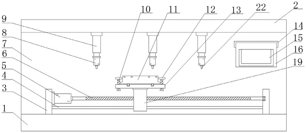
Fig. 1 is the overall structure schematic diagram of the high manganese steel lining plate processing device of the utility model.
Fig. 2 is the schematic diagram of the position structure of the wire block, the bearing plate, the positioning block and the positioning groove of the high manganese steel lining plate processing device of the utility model.
Fig. 3 is the utility model discloses a high manganese steel welt processingequipment's riser, L template, magnet and No. two magnet position structure schematic diagrams.
In the figure: 1. a base plate; 2. a top plate; 3. a vertical plate; 4. a guide bar; 5. a servo motor; 6. a reciprocating screw rod; 7. a vertical plate; 8. a motor; 9. an electric hydraulic push rod; 10. a screw; 11. a fixing plate; 12. pressing a plate; 13. a carrier plate; 14. a limiting groove; 15. placing the box; 16. an L-shaped plate; 17. a first magnet; 18. a magnet II; 19. silk blocks; 20. positioning blocks; 21. positioning a groove; 22. a drill bit.
Detailed Description
In order to make the technical means, creation features, achievement purposes and functions of the present invention easy to understand, the present invention is further described below with reference to the following embodiments.
As shown in figures 1-3, a high manganese steel lining plate processing device comprises a bottom plate 1, wherein one end of the top of the bottom plate 1 is provided with a vertical plate 3, the top of one side of the vertical plate 3 is provided with a servo motor 5, a power output end of one side of the servo motor 5 is provided with a reciprocating screw rod 6 through a coupler, the reciprocating screw rod 6 is provided with a screw block 19, the top of the screw block 19 is provided with a bearing plate 13 through a bolt, the top of the bearing plate 13 is provided with a fixing plate 11, the surfaces of the two sides of the top of the bearing plate 13 are provided with screw rods 10 through reserved threaded holes, the top of each screw rod 10 is provided with a pressing plate 12 corresponding to the corresponding fixing plate 11 through screws, one side of the top of the bottom plate 1 is provided with a vertical plate 7, one end of each vertical plate 7 is provided with a limiting groove 14, one side in each limiting groove 14 is connected with a first magnet 17 through gluing, an L-shaped plate 16 is arranged in each limiting groove 14, one end of the L-shaped plate 16 is connected with a second magnet 18 corresponding to the magnet 17 through gluing, and 16 one sides of L template are provided with places box 15, 7 tops of riser are provided with roof 2, and 2 bottoms of roof pass through electronic hydraulic push rod 9 of bolt installation, electronic hydraulic push rod 9 bottom output all passes through bolt and mounting bracket installation motor 8, and 8 bottom power take off ends of motor pass through shaft coupling installation drill bit 22.
Wherein, the bottom of one side of the vertical plate 3 is provided with a guide rod 4, and one end of the guide rod 4 penetrates through the wire block 19.
In this embodiment, as shown in fig. 1, the guide rod 4 can fix the angle of the wire block 19, thereby preventing the rotation of the wire block 19.
Positioning grooves 21 are formed in the surfaces of the two ends of the top of the bearing plate 13, and positioning blocks 20 corresponding to the positioning grooves 21 are arranged at the two ends of the bottom of the fixing plate 11.
In this embodiment, as shown in fig. 1 and 2, the positioning slot 21 and the positioning block 20 cooperate to determine the connection position of the fixing plate 11 and the bearing plate 13.
The other end of the top of the bottom plate 1 is provided with a connecting plate, a bearing is installed at the top of one side of the connecting plate through a reserved groove, and one end of the reciprocating screw rod 6 is located in the bearing.
In this embodiment, as shown in fig. 1, the connecting plate can support and limit the reciprocating screw rod 6 through a bearing.
And connecting threaded holes are formed in two ends of the top surface of the fixing plate 11.
In this embodiment, as shown in fig. 1 and 2, a person can fix an external clamp on the top of the fixing plate 11 through the connecting threaded hole, so that the person can fix the lining plate on the top of the fixing plate conveniently.
It should be noted that, the utility model relates to a high manganese steel welt processingequipment, in operation, personnel connect the external power supply mechanism with the external line of motor 8, servo motor 5 and electronic hydraulic push rod 9 earlier, on next step, personnel can place the corresponding external apparatus inside placing box 15, when needing to use the apparatus, personnel can manually exert certain power to L template 16, thereby make a magnet 17 and a magnet 18 separate, and then make L template 16 drive placing box 15 and break away from spacing groove 14, subsequently, personnel can place placing box 15 in the assigned position, thereby the personnel of being convenient for take its inside apparatus, and then reduce personnel's the operation degree of difficulty, on next step, personnel can fix the corresponding welt at the top of fixed plate 11, subsequently, personnel can be connected loading board 13 with fixed plate 11 through locating piece 20 and constant head tank 21, at this time, a person can manually rotate the screw 10, so that the pressing plate 12 presses the fixing plate 11 to connect and fix the bearing plate 13 and the fixing plate 11, next, the person can manually control the operation of the servo motor 5 through an external mechanism, at this time, the servo motor 5 drives the reciprocating screw rod 6 to rotate, so that the screw block 19 drives the bearing plate 13, the fixing plate 11 and the lining plate fixed at the top thereof to move, when the lining plate moves to a specified position, the person can manually open the corresponding motor 8, which can drive the corresponding drill bit 22 to rotate, and then, the person can manually control the corresponding electric hydraulic push rod 9, so that the output end thereof controls the drill bit 22 to descend to drill the lining plate, and the screw block 19 can move the lining plate fixed on the fixing plate 11 to the lower part of the drill bit 22 with a specified diameter as required, so as to drill holes with different diameters on the lining plate, need not to change drill bit 22, raise the efficiency, on next step, at this in-process, personnel can fix other welts at another fixed plate 11 top, and after the welt drilling at the inside fixed plate 11 top of this device was accomplished, personnel can be directly be connected another fixed plate 11 that has fixed the welt with loading board 13 to the time waste that causes when reducing the change welt, raise the efficiency.
The basic principles and the main features of the invention and the advantages of the invention have been shown and described above. It will be understood by those skilled in the art that the present invention is not limited to the above embodiments, and that the foregoing embodiments and descriptions are provided only to illustrate the principles of the present invention without departing from the spirit and scope of the present invention. The scope of the invention is defined by the appended claims and equivalents thereof.