Novel reactive compensation cabinet
Technical Field
The utility model belongs to the technical field of the compensation cabinet, specifically be a novel reactive power compensation cabinet.
Background
Reactive compensation plays a role in improving the power factor of a power grid in an electric power supply system, and is used for reducing the loss of a power supply transformer and a transmission line, improving the power supply efficiency and improving the power supply environment. The compensation device is reasonably selected, so that the loss of the power grid can be reduced to the maximum extent, the quality of the power grid is improved, and the reactive compensation cabinet is in an indispensable important position in the power system. Inside a large amount of electrical components of meeting installation of reactive compensation cabinet, can produce a large amount of heats during the use, if can not be timely with the heat effluvium, then can produce many unnecessary problems, if: insufficient component precision, equipment failure and the like, which have certain influence on the safe and stable operation of the power system and even cause accidents seriously.
The existing reactive compensation cabinet has poor heat dissipation effect and can not carry out uniform air-blowing cooling on the interior of the cabinet body; and the inevitable can bring the dust into the reactive power compensation cabinet during the heat dissipation, and the use of reactive power compensation cabinet also can be influenced to piling up in a large number of dust.
SUMMERY OF THE UTILITY MODEL
An object of the utility model is to provide a novel reactive compensation cabinet to solve the not good problem of cabinet body radiating effect.
In order to achieve the above object, the utility model provides a following technical scheme: the utility model provides a novel reactive compensation cabinet, the cabinet body, hinge connection has single to open the door on the cabinet body, the internal portion symmetry of cabinet is provided with the dispersion chamber, the inner wall symmetry in dispersion chamber is provided with the installing port, the radiator is installed to the installing port inboard, the upper end of the cabinet body is provided with the arch of taking a breath, it is provided with the heat transfer mouth in the arch of taking a breath.
Preferably, the inner wall of the cabinet body is uniformly provided with an air outlet pipe which is communicated with the dispersion cavity, and the inner wall of the dispersion cavity is cooled by blowing air to the interior of the cabinet body through the air outlet pipe.
Preferably, the outside of the cabinet body is connected with the installing frame, the installing frame inboard is provided with first dust screen, and setting up of first dust screen prevents that the dust from getting into the internal portion of cabinet from the installing port, be provided with location magnet on the installing frame, location magnet surface links to each other with the cabinet body, and the installing frame is fixed a position through the location magnet adsorption cabinet body, has made things convenient for the dismantlement clearance to first dust screen.
Preferably, the second dust screen has been cup jointed to the bellied outside of taking a breath, and the setting of second dust screen prevents that the dust from getting into the internal portion of cabinet from the heat transfer mouth, and the clearance is dismantled to the bellied outside convenience of taking a breath to the second dust screen to second dust screen cover simultaneously.
Preferably, the inner wall symmetry of the cabinet body is provided with the guide post, sliding connection has positioning bolt on the guide post, positioning bolt threaded connection has the board of shelving, the last symmetry of positioning bolt is provided with the mouth of tightening, and the mouth of tightening receives trapezoidal screw extrusion and inwards contracts to draw close and press from both sides tight guide post.
Preferably, trapezoidal screw holes are symmetrically formed in the surface of the shelving plate, the trapezoidal screw holes are small in top and large in bottom, along with the fact that the positioning bolts continuously upwards extend along the trapezoidal screw holes, the tightening openings of the positioning bolts inwards contract to clamp the guide columns to position the shelving plate, and the inner sides of the trapezoidal screw holes are in threaded connection with the positioning bolts.
Preferably, universal balls are symmetrically installed at the lower end of the cabinet body, and the cabinet body is convenient to move due to the arrangement of the universal balls.
Compared with the prior art, the beneficial effects of the utility model are that: the utility model discloses an evenly set up the outlet duct in the internal portion of cabinet, can be even dispel the heat to the internal portion of cabinet through the outlet duct when the radiator blows to the dispersion intracavity; through the arrangement of the first dustproof net and the second dustproof net, dust can be prevented from entering the cabinet body, and the first dustproof net and the second dustproof net are convenient to disassemble and clean; the position of the shelving plate on the guide rod can be adjusted by rotating the positioning bolt along the trapezoidal screw hole.
Drawings
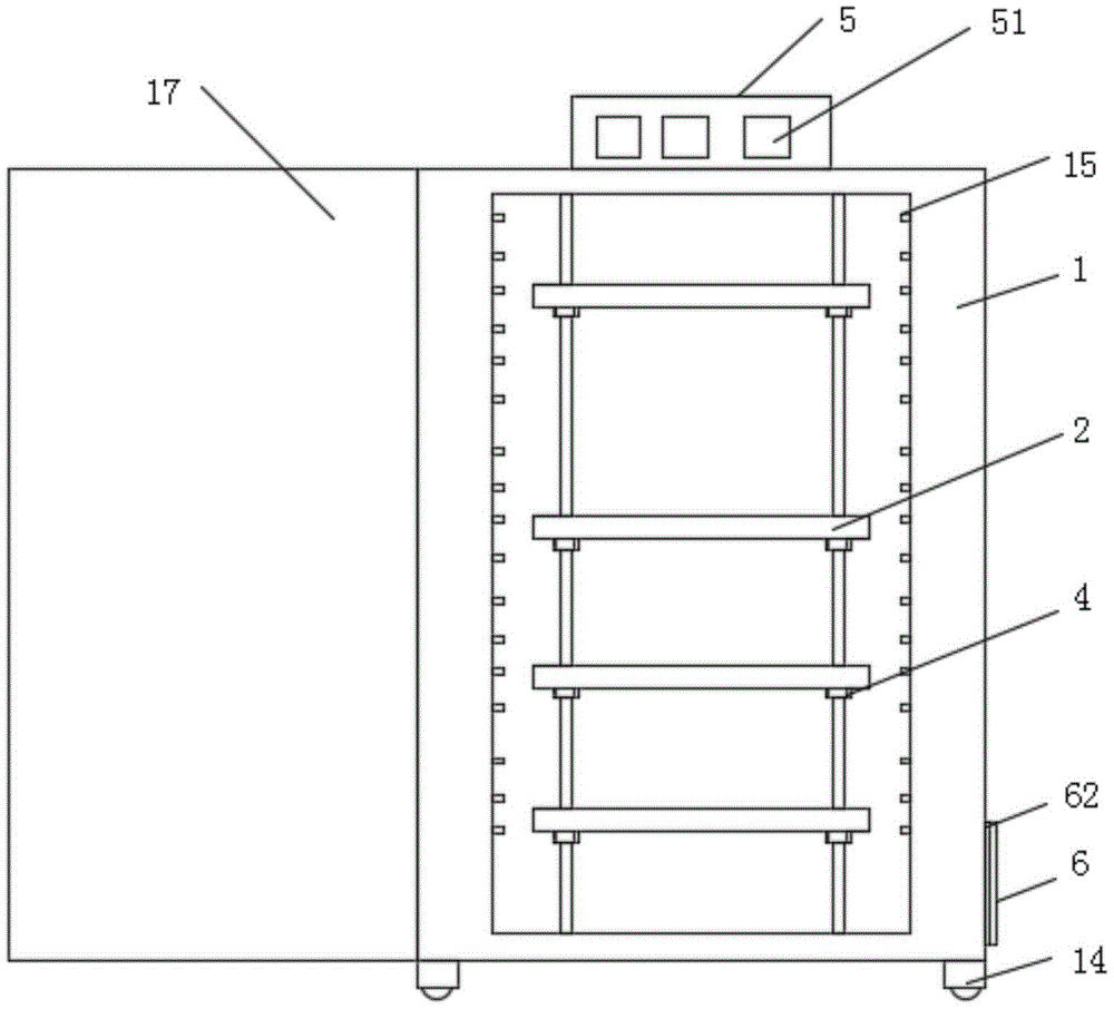
Fig. 1 is a schematic view of the overall structure of the present invention;
FIG. 2 is a sectional view of the overall structure of the present invention;
fig. 3 is an enlarged view of a portion a in fig. 2 according to the present invention;
fig. 4 is a schematic view of the positioning bolt of the present invention.
In the figure: the air conditioner comprises a cabinet body 1, a dispersing cavity 11, a mounting port 12, a radiator 13, a universal ball 14, an air outlet pipe 15, a guide column 16, a placing plate 2, a trapezoidal threaded hole 21, a positioning bolt 4, a tightening port 41, a ventilation bulge 5, a heat exchange port 51, a second dust screen 52, a mounting frame 6, a first dust screen 61 and a positioning magnet 62.
Detailed Description
Referring to fig. 1, 2 and 3, a novel reactive power compensation cabinet includes a cabinet body 1, a single-door 17 is hinged on the cabinet body 1, a dispersion chamber 11 is symmetrically arranged inside the cabinet body 1, mounting ports 12 are symmetrically arranged on the inner wall of the dispersion chamber 11, a radiator 13 is mounted on the inner side of the mounting port 12, a ventilation protrusion 5 is arranged at the upper end of the cabinet body 1, and a heat exchange port 51 is arranged on the ventilation protrusion 5.
Referring to fig. 1 and 2, the inner wall of the cabinet body 1 is uniformly provided with an air outlet pipe 15, the air outlet pipe 15 is communicated with the dispersion cavity 11, and the inner wall of the dispersion cavity 11 is blown to the inside of the cabinet body 1 through the air outlet pipe 15 for cooling.
Referring to fig. 2 and 3, the outer side of the cabinet body 1 is connected with the mounting frame 6, the inner side of the mounting frame 6 is provided with the first dust screen 61, the first dust screen 61 is arranged to prevent dust from entering the cabinet body 1 from the mounting opening 12, the mounting frame 6 is provided with the positioning magnet 62, the surface of the positioning magnet 62 is connected with the cabinet body 1, the mounting frame 6 adsorbs the cabinet body 1 through the positioning magnet 62 to be positioned, and the first dust screen 61 is convenient to detach and clean.
Referring to fig. 2, the second dust screen 52 is sleeved outside the ventilation protrusion 5, the second dust screen 52 prevents dust from entering the cabinet 1 through the heat exchanging port 51, and the second dust screen 52 is sleeved outside the ventilation protrusion 5 to facilitate the detachment and cleaning of the second dust screen 52.
Referring to fig. 2 and 4, the inner wall of the cabinet body 1 is symmetrically provided with guide posts 16, the guide posts 16 are slidably connected with positioning bolts 4, the positioning bolts 4 are in threaded connection with the placing plate 2, tightening ports 41 are symmetrically arranged on the positioning bolts 4, and the tightening ports 41 are pressed by the trapezoidal screw holes 21 to be inwardly contracted to clamp the guide posts 16.
Referring to fig. 2, trapezoidal screw holes 21 are symmetrically formed in the surface of the resting plate 2, the trapezoidal screw holes 21 are small in top and large in bottom, and as the positioning bolts 4 continuously move upwards along the trapezoidal screw holes 21, tightening ports 41 of the positioning bolts 4 are retracted inwards to clamp the guide posts 16 to position the resting plate 2, and the positioning bolts 4 are screwed into the inner sides of the trapezoidal screw holes 21.
Referring to fig. 1 and 2, universal balls 14 are symmetrically installed at the lower end of the cabinet body 1, and the movement of the cabinet body 1 is facilitated by the arrangement of the universal balls 14.
The working principle of the scheme is as follows: because the air outlet pipes 15 are uniformly arranged on the inner wall of the cabinet body 1, the air outlet pipes 15 are communicated with the dispersing cavity 11, the radiator 13 blows air into the dispersing cavity 11 when in operation, and the air in the dispersing cavity 11 can uniformly radiate the inside of the cabinet body 1 through the air outlet pipes 15;
the mounting frame 6 is adsorbed by the positioning magnet 62 to the cabinet body 1 and is mounted at the outer side of the mounting opening 12, dust and dust prevented by the first dust screen 61 at the inner side of the mounting frame 6 enter the cabinet body 1 from the mounting opening 12, the mounting frame 6 can be disassembled to clean the first dust screen 61, the second dust screen 52 is sleeved outside the ventilation bulge 5, the dust is prevented from entering the cabinet body 1 from the heat exchange opening 51 by the arrangement of the second dust screen 52, and the second dust screen 52 is convenient to disassemble and clean;
the shelving plate 2 upwards rotates along the trapezoidal screw hole 21 through the positioning bolt 4 to shrink the tightening port 41, so that the guide column 16 is clamped for positioning, and the positioning bolt 4 is downwards rotated to vertically move the shelving plate 2 along the guide rod 16 to adjust the position.