Road collision buffer pile
Technical Field
The utility model relates to a buffer pile technical field specifically is a road bumps buffer pile.
Background
At present, facilities such as collision avoidance columns and the like are basically cement and steel structures, and once major traffic safety accidents are easily caused by collision, serious vehicle damage can also be caused; the existing circular plastic barrel products on the market only can play a role in warning, have no buffering effect, and simultaneously have more damages due to the vulnerability of the plastic products, thereby influencing the appearance and the appearance of the market.
Disclosure of Invention
An object of the utility model is to provide a road bumps buffering stake to solve the problem that proposes among the above-mentioned background art.
In order to achieve the above object, the utility model provides a following technical scheme: a road collision buffer pile comprises a buffer pile body, a cover plate is arranged at the top of the buffer pile body, an upper enclosure is arranged above the buffer pile body, a lower enclosure is arranged below the buffer pile body, a road sign is arranged on the outer side of the buffer pile body, the buffer pile body comprises a front end energy-absorbing buffer area, a middle buffer area and a rear end buffer area, a plurality of splicing columns are arranged at one ends of the middle buffer area and the rear end buffer area, splicing holes connected with the splicing columns are formed in one end of the front end energy-absorbing buffer area and the other end of the middle buffer area, the front end energy-absorbing buffer area is connected to the front end of the middle buffer area, the rear end buffer area is connected to the rear end of the middle buffer area, and the upper enclosure and the lower enclosure comprise light reflecting layers, first wear-resistant layers, anti-aging layers, corrosion-resistant layers, second rubber layers, steel wire layers, first rubber layers and second wear-resistant layers;
middle buffer includes a plurality of buffers, and all be provided with the cellular riser of second buffering in every buffer of middle buffer and the rear end buffer, and the both sides of the cellular riser of every second buffering of middle buffer all are provided with first buffer tube, every first buffer tube top sets up to enclose on, first buffer tube below sets up to enclose down, the bottom of every first buffer tube all is provided with the gim peg hole, every first buffer tube all includes first barrel and second barrel, the second barrel sets up in first barrel, first barrel inboard is provided with many spliced poles, every spliced pole one end all is connected with the connecting block, connecting block one side is provided with buffer spring, buffer spring and connecting block all set up in the connecting pipe, connecting pipe one end is provided with the connection lid, be provided with the through-hole that is connected with the spliced pole on the connection lid.
Preferably, a plurality of first buffering honeycomb-shaped vertical plates are arranged in the front-end energy-absorbing buffer area, and one end of the front-end energy-absorbing buffer area is of an arc-shaped structure.
Preferably, the front end energy absorption buffer area one end and the one end of every buffer block all are provided with the handing-over groove, and the other end of every buffer block and the one end of rear end buffer area all are provided with the handing-over piece of being connected with the handing-over groove.
Preferably, second buffer cylinders are respectively arranged on two sides of the second buffer cellular vertical plates in the rear-end buffer area, an inner cylinder is arranged in each second buffer cylinder, a fixed pile hole is formed in the bottom of each inner cylinder, and a plurality of third buffer cellular vertical plates are arranged between the second buffer cylinders and the inner cylinders.
Preferably, the first buffer cylinder, the second buffer cylinder, the inner cylinder, the second buffer cellular vertical plate, the first buffer cellular vertical plate and the third buffer cellular vertical plate are all sequentially overlapped from outside to inside by the second rubber layer, the steel wire layer and the first rubber layer.
Preferably, the thicknesses of the second rubber layer, the steel wire layer and the first rubber layer of the upper periphery and the lower periphery are larger than those of the second rubber layer, the steel wire layer and the first rubber layer of the buffer pile body.
Compared with the prior art, the beneficial effects of the utility model are that: through the buffer pile body consisting of the reflecting layer, the first wear-resistant layer, the anti-aging layer, the corrosion-resistant layer, the second rubber layer, the steel wire layer, the first rubber layer and the second wear-resistant layer, the restoring force and the shock resistance of the buffer pile are improved, the buffer pile is not easy to break, long in service time, stable in performance, simple in structure, the thickness of the upper enclosure and the lower enclosure is increased, after the buffer pile body is impacted, the elastic toughness of the upper enclosure and the lower enclosure is improved, the buffer pile body is better attached to a car body, the protection is improved, the design of the impact bearing force is gradually increased through the step-by-step combination of the front end energy-absorbing buffer area, the middle buffer area and the rear end buffer area, the personal safety of a vehicle can be better protected, meanwhile, the buffer honeycomb-shaped vertical buffer plate and the buffer cylinder are arranged inside the buffer pile, the buffer structure consisting of the connecting column, the connecting pipe, the buffer spring, the connecting block and the connecting cover are arranged in the first cylinder, the impact force is reduced, and the buffer performance of the buffer cylinder is improved, and then the buffer pile is fixed through the fixing pile hole and the fixing bolt hole.
Drawings
FIG. 1 is an overall front view of the present invention;
FIG. 2 is a schematic view of the overall split structure of the present invention;
fig. 3 is an overall plan view of the present invention;
FIG. 4 is a bottom view of the utility model;
fig. 5 is a partial sectional view of the buffer pile body of the present invention;
FIG. 6 is a schematic diagram of the structure of the middle buffer area of the present invention;
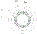
FIG. 7 is a front view of the buffer tube of the present invention;
fig. 8 is a sectional view of the buffer cylinder of the present invention;
fig. 9 is a schematic view of the connection columns of the present invention.
In the figure: 1. a buffer pile body; 2. a cover plate; 3. encircling the upper part; 4. lower enclosing; 5. a road sign; 6. a front end energy absorption buffer zone; 7. an intermediate buffer area; 8. a back-end buffer; 81. a second buffer cylinder; 9. a cross-connecting block; 10. a cross-over groove; 11. inserting the column; 12. inserting holes; 13. fixing pile holes; 14. a fixing bolt hole; 15. a first buffer honeycomb-shaped vertical plate; 16. a second buffer honeycomb-shaped vertical plate; 17. a first buffer cylinder; 171. a first cylinder; 172. a second cylinder; 173. connecting columns; 174. a connecting pipe; 175. a buffer spring; 176. connecting blocks; 177. a connecting cover; 18. an inner barrel; 19. a third buffer honeycomb-shaped vertical plate; 101. a light-reflecting layer; 102. a first wear resistant layer; 103. an anti-aging layer; 104. a corrosion-resistant layer; 105. a second rubber layer; 106. a steel wire layer; 107. a first rubber layer; 108. a second wear resistant layer.
Detailed Description
The technical solutions in the embodiments of the present invention will be described clearly and completely with reference to the accompanying drawings in the embodiments of the present invention, and it is obvious that the described embodiments are only some embodiments of the present invention, not all embodiments. Based on the embodiments in the present invention, all other embodiments obtained by a person skilled in the art without creative work belong to the protection scope of the present invention.
In the description of the present invention, it should be noted that the terms "vertical", "upper", "lower", "horizontal", and the like indicate orientations or positional relationships based on the orientations or positional relationships shown in the drawings, and are only for convenience of description and simplification of description, but do not indicate or imply that the device or element referred to must have a specific orientation, be constructed in a specific orientation, and be operated, and thus should not be construed as limiting the present invention.
In the description of the present invention, it should also be noted that, unless otherwise explicitly specified or limited, the terms "disposed," "mounted," "connected," and "connected" are to be construed broadly, e.g., as meaning either a fixed connection, a removable connection, or an integral connection; can be mechanically or electrically connected; they may be connected directly or indirectly through intervening media, or they may be interconnected between two elements. The specific meaning of the above terms in the present invention can be understood according to specific situations by those skilled in the art.
Referring to fig. 1-9, the present invention provides a technical solution: the utility model provides a road collision buffering stake, including buffering stake body 1, buffering stake body 1 top is provided with apron 2, the top of buffering stake body 1 is for enclosing 3 on, the below of buffering stake body 1 is for enclosing 4 down, the buffering stake body 1 outside is provided with road sign 5, buffering stake body 1 includes front end energy-absorbing buffer 6, middle buffer 7 and rear end buffer 8's one end all is provided with many spliced poles 11, the spliced eye 12 that is connected with spliced pole 11 is all provided with to the one end of front end energy-absorbing buffer 6 and the other end of middle buffer 7, front end energy-absorbing buffer 6 connects the front end at middle buffer 7, rear end buffer 8 connects the rear end at middle buffer 7, buffering stake body 1, go up enclose 3 and enclose 4 down and all include reflector layer 101, first layer 102, ageing resistance layer 103, corrosion resistance layer 104, second rubber layer 105, A steel wire layer 106, a first rubber layer 107 and a second wear-resistant layer 108;
the middle buffer area 7 comprises a plurality of buffer blocks, second buffer cellular risers 16 are arranged in each buffer block of the middle buffer area 7 and in the rear buffer area 8, first buffer cylinders 17 are arranged on two sides of each second buffer cellular riser 16 of the middle buffer area 7, an upper enclosure 3 is arranged above each first buffer cylinder 17, a lower enclosure 4 is arranged below each first buffer cylinder 17, a fixing bolt hole 14 is arranged at the bottom of each first buffer cylinder 17, each first buffer cylinder 17 comprises a first cylinder 171 and a second cylinder 172, the second cylinder 172 is arranged in the first cylinder 171, a plurality of connecting columns 173 are arranged on the inner side of the first cylinder 171, one end of each connecting column 173 is connected with a connecting block 176, a buffer spring 175 is arranged on one side of the connecting block 176, the buffer spring 175 and the connecting block 176 are arranged in the connecting pipe 174, a connecting cover 177 is arranged at one end of the connecting pipe 174, the connection cover 177 is provided with a through hole connected with the connection post 173.
A plurality of first buffering honeycomb-shaped vertical plates 15 are arranged in the front-end energy-absorbing buffer area 6, and one end of the front-end energy-absorbing buffer area 6 is of an arc-shaped structure.
One end of the front end energy absorption buffer area 6 and one end of each buffer block are provided with a cross connecting groove 10, and the other end of each buffer block and one end of the rear end buffer area 8 are provided with a cross connecting block 9 connected with the cross connecting groove 10.
Second buffer cylinders 81 are respectively arranged on two sides of the second buffer cellular vertical plates 16 in the rear-end buffer area 8, an inner cylinder 18 is arranged in each second buffer cylinder 81, a fixed pile hole 13 is arranged at the bottom of each inner cylinder 18, and a plurality of third buffer cellular vertical plates 19 are arranged between the second buffer cylinders 81 and the inner cylinders 18.
The first buffer cylinder 17, the second buffer cylinder 81, the inner cylinder 18, the second buffer cellular upright plate 16, the first buffer cellular upright plate 15 and the third buffer cellular upright plate 19 are all sequentially overlapped from outside to inside by a second rubber layer 105, a steel wire layer 106 and a first rubber layer 107.
The thicknesses of the second rubber layer 105, the steel wire layer 106 and the first rubber layer 107 of the upper periphery 3 and the lower periphery 4 are all larger than the thicknesses of the second rubber layer 105, the steel wire layer 106 and the first rubber layer 107 of the buffer pile body 1.
The working principle is as follows: when the buffer pile is used, one end of the middle buffer area 7 is connected with the cross-connecting groove 10 and the plug-in hole 12 at one end of the front end energy-absorbing buffer area 6 through the cross-connecting block 9 and the plug-in post 11, the rear end buffer area 8 is connected with the cross-connecting groove 10 and the plug-in hole 12 at one end of the middle buffer area 7 through the cross-connecting block 9 and the plug-in post 11, the front end energy-absorbing buffer area 6, the middle buffer area 7 and the rear end buffer area 8 are assembled into the buffer pile body 1, the fixed pile hole 13 is fixed through piling, the fixed bolt hole 14 is fixed through an expansion screw or a threaded steel, an automobile tire is placed in a buffer cylinder 17 of the middle buffer area 7, the stability of the buffer pile body 1 is improved, the cover plate 2 is connected to the top of the buffer pile body 1, when the buffer pile body 1 is impacted, the front end energy-absorbing buffer area 6, the middle buffer area 7 and the rear end buffer area 8 gradually buffer, the first buffer cellular upright plate 15 in the front end energy-absorbing buffer area 6 buffers, the first buffer cylinder 17 in the middle buffer area 7 buffers, the first cylinder 171 is impacted, the connecting column 17 enters the connecting pipe 174, the connecting block 176 is driven to extrude the buffer spring 175 to achieve the buffering effect, and the second buffer cylinder 81, the third buffer cellular vertical plate 18 and the inner cylinder 18 in the rear buffer area 8 buffer finally.
Although embodiments of the present invention have been shown and described, it will be appreciated by those skilled in the art that changes, modifications, substitutions and alterations can be made in these embodiments without departing from the principles and spirit of the invention, the scope of which is defined in the appended claims and their equivalents.