CN214445549U - Back shaft location frock about electric motor car - Google Patents
Back shaft location frock about electric motor car Download PDFInfo
- Publication number
- CN214445549U CN214445549U CN202022586950.0U CN202022586950U CN214445549U CN 214445549 U CN214445549 U CN 214445549U CN 202022586950 U CN202022586950 U CN 202022586950U CN 214445549 U CN214445549 U CN 214445549U
- Authority
- CN
- China
- Prior art keywords
- back shaft
- electric telescopic
- base
- sides
- telescopic rod
- Prior art date
- Legal status (The legal status is an assumption and is not a legal conclusion. Google has not performed a legal analysis and makes no representation as to the accuracy of the status listed.)
- Expired - Fee Related
Links
- 238000003825 pressing Methods 0.000 claims description 12
- 238000005498 polishing Methods 0.000 abstract description 11
- 238000004519 manufacturing process Methods 0.000 abstract description 2
- 230000000694 effects Effects 0.000 description 6
- 238000000034 method Methods 0.000 description 6
- 238000003860 storage Methods 0.000 description 2
- 230000004075 alteration Effects 0.000 description 1
- 230000009286 beneficial effect Effects 0.000 description 1
- 238000012986 modification Methods 0.000 description 1
- 230000004048 modification Effects 0.000 description 1
- 230000001105 regulatory effect Effects 0.000 description 1
- 238000006467 substitution reaction Methods 0.000 description 1
Images


Landscapes
- Grinding And Polishing Of Tertiary Curved Surfaces And Surfaces With Complex Shapes (AREA)
- Grinding Of Cylindrical And Plane Surfaces (AREA)
Abstract
The utility model belongs to the technical field of electric vehicle manufacturing, in particular to a positioning tool for left and right support shafts of an electric vehicle, which comprises a base, the two sides of the top end of the base are both provided with supporting rods, one side of each supporting rod opposite to the corresponding supporting rod is provided with an adjusting device, a supporting shaft is arranged between the two adjusting devices, the two ends of the supporting shaft are respectively connected with the two adjusting devices in a clamping way, the supporting shaft is provided with a clamping device, the utility model is provided with the adjusting devices which are matched with the clamping device, when the supporting shaft at the clamping position needs to be polished, the two adjusting devices clamp the supporting shaft through the sucking disc under the action of the first electric telescopic rod, the supporting shaft slides in the clamping device under the action of the first electric telescopic rod, thereby let out to press from both sides and get the position and conveniently polish, solved current grinding device and can not carry out the problem of polishing comprehensively to the back shaft in the work of polishing.
Description
Technical Field
The utility model belongs to the technical field of the electric motor car is made, concretely relates to back shaft location frock about electric motor car.
Background
An electric bicycle is a mechatronic personal transportation tool which takes a storage battery as auxiliary energy and is provided with an electric motor, a controller, the storage battery, a rotating handle brake handle and other operating components and a display instrument system on the basis of a common bicycle.
Back shaft about need when the equipment electric motor car, back shaft need carry out the work of polishing to the back shaft in manufacturing process, and current grinding tool when polishing the back shaft, can not polish to the position of pressing from both sides the clamp, need shut down and replace and polish, greatly reduced the efficiency of polishing of device.
SUMMERY OF THE UTILITY MODEL
An object of the utility model is to provide a back shaft location frock about electric motor car to it can not carry out the problem of polishing comprehensively to the back shaft to propose current grinding device in the work of polishing in solving above-mentioned background art.
In order to achieve the above object, the utility model provides a following technical scheme: the utility model provides a back shaft location frock about electric motor car, includes the base, the bracing piece, two are all installed to the both sides on base top adjusting device, two are all installed to the relative one side of bracing piece be provided with the back shaft between the adjusting device, the both ends of back shaft are connected with two adjusting device blocks respectively, it gets the device to be provided with the clamp on the back shaft, the bottom of getting the device and the top fixed connection of base are got to the clamp, it is connected with the back shaft block to get the device, be provided with the controller on the base.
Preferably, the clamping device comprises a fixed seat and a gasket, the bottom of the fixed seat is fixedly connected with the top of the base, a groove is formed in one side of the top end of the fixed seat, and the gasket is fixedly connected with the bottom inside the groove.
Preferably, the spout has been seted up to the top of recess, the one end of spout bottom extends to the inside of recess, the inside of spout is provided with the briquetting, the briquetting is at the inside sliding connection of spout and recess, and the back shaft block is connected between briquetting and gasket, the cross-section of back shaft is circular.
Preferably, one end of the pressing block is provided with a second electric telescopic rod, and the bottom end of the second electric telescopic rod is fixedly connected with the bottom of the fixing seat.
Preferably, adjusting device includes first electric telescopic handle and sucking disc, first electric telescopic handle's one end and bracing piece fixed connection, first electric telescopic handle's the other end and one side fixed connection of sucking disc.
Preferably, one side of the sucker, which is far away from the first electric telescopic rod, is provided with a limiting groove, and the limiting groove is connected with one end of the supporting shaft in a clamping manner.
Compared with the prior art, the beneficial effects of the utility model are that:
(1) the utility model discloses set up and press from both sides the adjusting device that the device was mutually supported with the clamp, when needs were polished the back shaft of pressing from both sides the position of getting, two adjusting device pass through the sucking disc with the back shaft under first electric telescopic handle's effect and clip, and the inside slip of device is being pressed from both sides to the back shaft is pressing from both sides under the effect through first electric telescopic handle to let out the clamp and get the position and conveniently polish, solved current grinding device and can not carry out the problem of polishing comprehensively to the back shaft in the work of polishing.
(2) The utility model discloses set up the spacing groove that is located the sucking disc, the spacing groove carries out the in-process that the clamp was got at adjusting device to the back shaft and plays skid-proof effect, lets the back shaft can not let the back shaft drop at the in-process of adjusting device work, causes the condition of back shaft damage to appear.
Drawings
Fig. 1 is a schematic structural view of the present invention;
fig. 2 is a schematic structural view of the clamping device of the present invention;
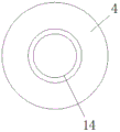
FIG. 3 is a schematic view of the sucking disc and the limiting groove of the present invention;
in the figure: 1-a base; 2-a support rod; 3-a first electric telescopic rod; 4-a sucker; 5-briquetting; 6-a gripping device; 7-a regulating device; 8, a fixed seat; 9-a groove; 10-a controller; 11-a chute; 12-a gasket; 13-a second electric telescopic rod; 14-a limiting groove; 15-supporting the shaft.
Detailed Description
The technical solutions in the embodiments of the present invention will be described clearly and completely with reference to the accompanying drawings in the embodiments of the present invention, and it is obvious that the described embodiments are only some embodiments of the present invention, not all embodiments. Based on the embodiments in the present invention, all other embodiments obtained by a person skilled in the art without creative work belong to the protection scope of the present invention.
Referring to fig. 1-3, the present invention provides a technical solution: the utility model provides a back shaft location frock about electric motor car, including base 1, bracing piece 2 is all installed to the both sides on base 1 top, adjusting device 7 is all installed to two 2 relative one sides of bracing piece, be provided with back shaft 15 between two adjusting device 7, the both ends of back shaft 15 are connected with two adjusting device 7 blocks respectively, it gets device 6 to be provided with the clamp on back shaft 15, the bottom of getting device 6 and base 1's top fixed connection is got to the clamp, it is connected with back shaft 15 blocks to get device 6, be provided with controller 10 on the base 1.
When needs are polished the back shaft 15 of pressing from both sides the position of getting, two adjusting device 7 are under the effect of first electric telescopic handle 3 with back shaft 15 through sucking disc 4 clip, and back shaft 15 slides in the inside of pressing from both sides the device 6 of getting under the effect through first electric telescopic handle 3 to let out press from both sides and get the position and conveniently polish, solved current grinding device can not polish the problem comprehensively to the back shaft in the work of polishing.
Further, press from both sides and get device 6 and include fixing base 8 and gasket 12, the bottom of fixing base 8 and base 1's top fixed connection, recess 9 has been seted up to one side on fixing base 8's top, and gasket 12 all adopts the rubber material at the inside bottom fixed connection of recess 9, gasket 12 and briquetting 5, and protection back shaft 15 can not cause the damage to back shaft 15's surface at the in-process of polishing.
Specifically, a sliding groove 11 is formed above the groove 9, one end of the bottom of the sliding groove 11 extends into the groove 9, a pressing block 5 is arranged inside the sliding groove 11, the pressing block 5 is connected with the groove 9 in a sliding mode inside the sliding groove 11, a supporting shaft 15 is connected between the pressing block 5 and a gasket 12 in a clamping mode, and the cross section of the supporting shaft 15 is circular.
It is worth to say that, one end of the pressing block 5 is provided with a second electric telescopic rod 13, and the bottom end of the second electric telescopic rod 13 is fixedly connected with the bottom of the fixed seat 8.
Further, adjusting device 7 includes first electric telescopic handle 3 and sucking disc 4, the one end and the 2 fixed connection of bracing piece of first electric telescopic handle 3, the other end and one side fixed connection of sucking disc 4 of the other end of first electric telescopic handle 3.
Further, one side that first electric telescopic handle 3 was kept away from to sucking disc 4 is provided with spacing groove 14, and spacing groove 14 is connected with the one end block of back shaft 15, and spacing groove 14 plays skid-proof effect at adjusting device 7 in-process that back shaft 15 got, lets back shaft 15 can not let back shaft 15 drop at the in-process of adjusting device 7 work, causes the condition of back shaft 15 damage to appear.
In summary, the first electric telescopic rod 3 and the second electric telescopic rod 13 are both electrically connected to the controller 10.
The first electric telescopic rod 3 and the second electric telescopic rod 13 are both LX700 series electric telescopic rods, and the controller 10 is KY 02S.
The utility model discloses a theory of operation and use flow: when the utility model is used, the supporting shaft 15 enters the clamping device 6 through the groove 9 on the fixing seat 8, the pressing block 5 enters the groove 9 from the inside of the sliding groove 11 under the action of the second electric telescopic rod 13, the supporting shaft 15 is pressed on the gasket 12, the fixing action of the supporting shaft 15 is completed, when the supporting shaft 15 at the clamping position 6 needs to be polished, the adjusting devices 7 on the supporting rods 2 at the two sides of the top end of the base 1 clamp the supporting shaft 15 at the two ends of the supporting shaft 15, in the clamping process, the first electric telescopic rod 3 drives the suction disc 4 to approach one end of the supporting shaft 15, so that the supporting shaft 15 is clamped into the limiting groove 14, meanwhile, the second electric telescopic rod 13 resets, the supporting shaft 15 is loosened, the supporting shaft 15 horizontally moves in the groove 9 under the coordination of the first electric telescopic rod 4 inside the two adjusting devices 7, leaking out of the unground area.
Although embodiments of the present invention have been shown and described, it will be appreciated by those skilled in the art that changes, modifications, substitutions and alterations can be made in these embodiments without departing from the principles and spirit of the invention, the scope of which is defined in the appended claims and their equivalents.
Claims (6)
1. The utility model provides a back shaft location frock about electric motor car, includes base (1), its characterized in that: bracing piece (2), two are all installed to the both sides on base (1) top adjusting device (7), two are all installed to bracing piece (2) relative one side be provided with back shaft (15) between adjusting device (7), the both ends of back shaft (15) are connected with two adjusting device (7) blocks respectively, it gets device (6) to be provided with on back shaft (15) to press from both sides, press from both sides the bottom of getting device (6) and the top fixed connection of base (1), it is connected with back shaft (15) block to press from both sides to get device (6), be provided with controller (10) on base (1).
2. The electric vehicle left and right support shaft positioning tool according to claim 1, characterized in that: the clamping device (6) comprises a fixed seat (8) and a gasket (12), the bottom of the fixed seat (8) is fixedly connected with the top of the base (1), a groove (9) is formed in one side of the top end of the fixed seat (8), and the gasket (12) is fixedly connected with the bottom of the groove (9).
3. The electric vehicle left and right support shaft positioning tool according to claim 2, characterized in that: spout (11) have been seted up to the top of recess (9), the one end of spout (11) bottom extends to the inside of recess (9), the inside of spout (11) is provided with briquetting (5), briquetting (5) are at the inside sliding connection of spout (11) and recess (9), and back shaft (15) block between briquetting (5) and gasket (12) is connected, the cross-section of back shaft (15) is circular.
4. The electric vehicle left and right support shaft positioning tool according to claim 3, characterized in that: one end of the pressing block (5) is provided with a second electric telescopic rod (13), and the bottom end of the second electric telescopic rod (13) is fixedly connected with the bottom of the fixing seat (8).
5. The electric vehicle left and right support shaft positioning tool according to claim 1, characterized in that: adjusting device (7) include first electric telescopic handle (3) and sucking disc (4), the one end and bracing piece (2) fixed connection of first electric telescopic handle (3), the other end of first electric telescopic handle (3) and one side fixed connection of sucking disc (4).
6. The electric vehicle left and right support shaft positioning tool according to claim 5, characterized in that: one side of the sucker (4) far away from the first electric telescopic rod (3) is provided with a limiting groove (14), and the limiting groove (14) is connected with one end of the supporting shaft (15) in a clamping manner.
Priority Applications (1)
| Application Number | Priority Date | Filing Date | Title |
|---|---|---|---|
| CN202022586950.0U CN214445549U (en) | 2020-11-11 | 2020-11-11 | Back shaft location frock about electric motor car |
Applications Claiming Priority (1)
| Application Number | Priority Date | Filing Date | Title |
|---|---|---|---|
| CN202022586950.0U CN214445549U (en) | 2020-11-11 | 2020-11-11 | Back shaft location frock about electric motor car |
Publications (1)
| Publication Number | Publication Date |
|---|---|
| CN214445549U true CN214445549U (en) | 2021-10-22 |
Family
ID=78182335
Family Applications (1)
| Application Number | Title | Priority Date | Filing Date |
|---|---|---|---|
| CN202022586950.0U Expired - Fee Related CN214445549U (en) | 2020-11-11 | 2020-11-11 | Back shaft location frock about electric motor car |
Country Status (1)
| Country | Link |
|---|---|
| CN (1) | CN214445549U (en) |
-
2020
- 2020-11-11 CN CN202022586950.0U patent/CN214445549U/en not_active Expired - Fee Related
Similar Documents
| Publication | Publication Date | Title |
|---|---|---|
| CN210909286U (en) | Terminal surface grinding device of box transformer cabinet curb plate | |
| CN106271927A (en) | A kind of plate body polishing environmental-protecting dust device | |
| CN113997083A (en) | Cutting and polishing integrated device for lithium battery processing | |
| CN110193770B (en) | Novel polishing equipment for hardware fitting machining | |
| CN110142661A (en) | A kind of glass processing grinding device | |
| CN215239896U (en) | Cutting grinding device suitable for PE pipe production usefulness | |
| CN210024767U (en) | Grinding machine for polishing truck instrument panel | |
| CN212794314U (en) | Copper pipe grinding device | |
| CN210938574U (en) | Polishing device for crystal products | |
| CN112123106A (en) | Stainless steel elbow pipe fitting surface finishing device | |
| CN216967247U (en) | Fine grinding device for motorcycle frame | |
| CN218284991U (en) | A environmental protection grinding device for non-standard automation equipment | |
| CN209036663U (en) | A kind of plastic-sucking tray production cutting equipment | |
| CN213498128U (en) | Processing system for water heater shell | |
| CN211841272U (en) | Polishing and grinding equipment for shaft parts | |
| CN212287001U (en) | Five metals grinding device who facilitates use | |
| CN212858844U (en) | Adhesive tape reciprocating polisher | |
| CN210413834U (en) | Part double-side surface grinding machine | |
| CN212762686U (en) | Hierarchical polishing grinding device of accurate mould | |
| CN213106200U (en) | Machining burnishing device | |
| CN210909406U (en) | Hand-held type polisher | |
| CN213998825U (en) | Brake arm grinding device | |
| CN213917551U (en) | Automobile sealing strip production grinds thick device | |
| CN206382983U (en) | A kind of sander of metallic article processing | |
| CN213828271U (en) | Circuit board edge grinding machine |
Legal Events
| Date | Code | Title | Description |
|---|---|---|---|
| GR01 | Patent grant | ||
| GR01 | Patent grant | ||
| CF01 | Termination of patent right due to non-payment of annual fee |
Granted publication date: 20211022 |
|
| CF01 | Termination of patent right due to non-payment of annual fee |