Novel can have enough to meet need ground storehouse roof and go back to top to consolidate device
Technical Field
The utility model relates to a novel can have enough to meet need ground storehouse roof and return reinforcing apparatus belongs to construction technical field.
Background
With the improvement of the modernization level of Chinese cities, high-rise buildings appear like bamboo shoots in spring after raining. In order to utilize the space more effectively, part of the construction units arrange the construction site on the top plate of the completed basement. After the top plate of the ground warehouse is sealed, the main building is still in a structural construction stage, various vehicles such as material vehicles, concrete vehicles and the like are inevitably required to go to the ground warehouse to run due to construction requirements, and a material yard and a processing factory are transferred to the top plate of the ground warehouse. The top plate of the ground reservoir bears alternating live load, constant load and concentrated load, the stress condition is complex, and most of the stress condition exceeds the design load.
Based on the situation, the conventional method is that the formwork support is jacked back, and the formwork support at the overhanging structure part is independently erected and is not detached. The method occupies a large amount of turnover frame materials, influences the second structure of the ground warehouse and the decoration construction, especially influences the process alternation and is not beneficial to the guarantee of the construction period due to the short project of the construction period.
When the basement formwork support is erected, a single 18# I-steel is vertically erected at a certain interval at a test point, the bottom end of the test point is supported on the bottom plate structure, the top end of the test point is embedded in the top plate structure, the formwork support is normally dismantled, and the I-steel supports and reinforces. Although the method avoids the back jacking of the steel pipe support frame, because a single I-steel is long and heavy, a large amount of labor is consumed during burying, and the support needs to be cut off during dismantling, so that the construction of the ceiling putty is influenced. When the operation is carried out to the next construction site, the length needs to be adjusted, and the waste is serious. Meanwhile, the method lacks theoretical research on stress analysis and reinforcement effect.
SUMMERY OF THE UTILITY MODEL
An object of the utility model is to provide a convenient operation, labour saving and time saving, the novel ground storehouse roof that can have enough to meet need reinforcing apparatus that backs that improves efficiency of construction, the device has not only realized the reinforcement of backing back of ground storehouse roof, but also has the installation convenient, height-adjustable, practices thrift engineering cost's advantage.
In order to achieve the above purpose, the utility model adopts the following technical scheme: a novel recyclable ground warehouse top plate back jacking reinforcing device comprises a lifting vehicle and a lifting column, wherein the lifting vehicle comprises a base, a lead screw, a servo motor, a bracket and the lifting column, the lifting column is vertically fixed on the base, the bracket is connected onto the lifting column in a sliding manner, the lead screw is rotatably connected to the center of the lifting column, the servo motor is installed at the top of the lifting column and is in transmission connection with the lead screw, and a nut pair matched with the lead screw is fixedly installed on the bracket; the jacking column comprises an I-shaped steel frame and a channel steel welding frame sleeved on the I-shaped steel frame and connected with the I-shaped steel frame in a sliding mode, a top plate is welded at the top of the channel steel welding frame, adjusting screw assemblies are symmetrically hinged to the lower end of the channel steel welding frame, the lower ends of the adjusting screw assemblies are fixed on the I-shaped steel frame through bolts, and the end portion of the bracket is supported at the bottom of the channel steel welding frame.
Furthermore, guide grooves are formed in two sides of the lifting column, idler wheels are mounted at the end portions of the brackets, and the idler wheels are arranged in the guide grooves and are in rolling fit with the guide grooves.
Furthermore, universal brake wheels are installed at the bottom of the base.
Furthermore, one side of the lifting column is fixedly provided with a handrail.
Further, the lower part is installed respectively in the outside of channel-section steel welding frame and is removed the wheel and remove the wheel with upper portion, to welding in channel-section steel welding frame lower extreme both sides have "U" type support, "U" type support in install outer leading wheel, and outer leading wheel and I-steel frame rolling contact, install the spacing wheel of three-dimensional in the top bilateral symmetry of I-steel frame, the inboard rolling contact of the spacing wheel of three-dimensional and channel-section steel welding frame.
Furthermore, the lower part of the channel steel welding frame is fixedly connected with an angle plate, the adjusting screw component comprises an adjusting cylinder, and an upper adjusting screw and a lower adjusting screw which are respectively in threaded connection with the two ends of the adjusting cylinder, the upper adjusting screw is hinged with the angle plate through a screw pin, and the lower adjusting screw is fixedly connected with the I-shaped steel frame through a bolt.
Furthermore, the lower end of the I-shaped steel frame is symmetrically connected with channel steel supports through bolts, and pull rods are connected between the channel steel supports and the I-shaped steel frame through bolts.
Furthermore, rib plates are symmetrically welded between the top of the top plate and the channel steel welding frame.
Since the technical scheme is used, the utility model discloses an advantage has below: the utility model discloses a servo motor of lift truck provides power, and the lead screw through the lift truck rotates the channel-section steel welded frame vertical motion that drives bracket and jacking post, realizes the roof back of different headroom height ground storehouses and consolidates the condition. Compare in traditional roof back-pushing reinforced structure, the utility model discloses not only can realize altitude mixture control, but also repeatedly usable has strong adaptability, easy and simple to handle high-efficient, accelerate construction progress, practice thrift the advantage of cost.
Drawings
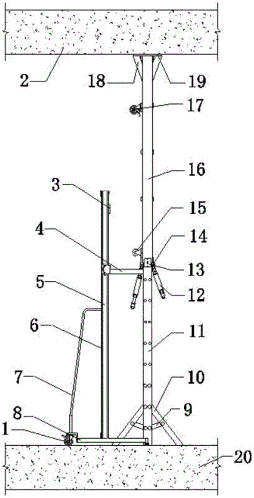
Fig. 1 is a schematic structural diagram of the present invention;
FIG. 2 is a schematic structural view of the lift car;
FIG. 3 is a schematic structural view of a jacking leg;
FIG. 4 is a schematic view of the lower structure of the jacking leg;
FIG. 5 is a schematic view of the lower end structure of the channel steel welding frame;
fig. 6 is a schematic structural view of the bracket.
Description of reference numerals: 1-universal brake wheel, 2-top plate of a garage, 3-servo motor, 4-bracket, 5-lead screw, 6-lifting column, 7-handrail, 8-base, 9-pull rod, 10-channel steel bracket, 11-I-shaped steel frame, 12-adjusting screw component, 13-U-shaped bracket, 14-angle plate, 15-lower moving wheel, 16-channel steel welding frame, 17-upper moving wheel, 18-ribbed plate, 19-top plate, 20-bottom plate of the garage, 21-nut pair, 22-three-way limiting wheel, 23-roller, 24-bolt, 25-adjusting cylinder, 26-upper adjusting screw, 27-lower adjusting screw, 28-outer guide wheel and 29-screw pin.
Detailed Description
The technical solutions in the embodiments of the present invention will be described clearly and completely with reference to the accompanying drawings in the embodiments of the present invention, and it is obvious that the described embodiments are only some embodiments of the present invention, not all embodiments. Based on the embodiments in the present invention, all other embodiments obtained by a person skilled in the art without creative work belong to the protection scope of the present invention.
Referring to fig. 1 to 6, a novel recyclable basement roof back-jacking reinforcing device comprises a lift truck and a jacking column, wherein the lift truck comprises a base 8, a screw 5, a servo motor 3, a bracket 4 and the jacking column 6, the lifting column 6 is vertically fixed on the base 8, the bracket 4 is connected on the lifting column 6 in a sliding manner, guide grooves are formed in two sides of the lifting column 6, a roller 23 is installed at the end portion of the bracket 4, and the roller 23 is arranged in the guide grooves and is matched with the guide grooves in a rolling manner. The center of the lifting column 6 is rotatably connected with a lead screw 5, the top of the lifting column 6 is provided with a servo motor 3, the servo motor 3 is in transmission connection with the lead screw 5, and a nut pair 21 matched with the lead screw 5 is fixedly arranged on the bracket 4; the jacking column comprises an I-shaped steel frame 11 and a channel steel welding frame 16 which is sleeved on the I-shaped steel frame 11 and is in sliding connection with the I-shaped steel frame 11, a top plate 19 is welded at the top of the channel steel welding frame 16, adjusting screw assemblies 12 are symmetrically hinged to the lower end of the channel steel welding frame 16, the lower ends of the adjusting screw assemblies 12 are fixed on the I-shaped steel frame 11 through bolts 24, and the end portion of the bracket 4 is supported at the bottom of the channel steel welding frame 16.
Further, universal brake wheel 1 is installed to the bottom of base 8, one side fixed mounting of lift post 6 has handrail 7, is convenient for remove the lift truck.
Further, the outer side of the channel steel welding frame 16 is respectively provided with a lower moving wheel 15 and an upper moving wheel 17, two sides of the lower end of the channel steel welding frame 16 are oppositely welded with a U-shaped support 13, an outer guide wheel 28 is arranged in the U-shaped support 13, the outer guide wheel 28 is in rolling contact with the I-shaped steel frame 11, two sides of the top of the I-shaped steel frame 11 are symmetrically provided with three-way limiting wheels 22, and the three-way limiting wheels 22 are in rolling contact with the inner side of the channel steel welding frame 16.
Further, an angle plate 14 is fixedly connected to the lower portion of the channel steel welding frame 16, the adjusting screw assembly 12 includes an adjusting cylinder 25, and an upper adjusting screw 26 and a lower adjusting screw 27 which are respectively in threaded connection with two ends of the adjusting cylinder 25, the upper adjusting screw 26 is hinged to the angle plate 14 through a screw pin 29, and the lower adjusting screw 27 is fixedly connected to the i-shaped steel frame 11 through a bolt 24.
Further, the lower end of the i-shaped steel frame 11 is symmetrically connected with channel steel brackets 10 through bolts, and a pull rod 9 is connected between the channel steel brackets 10 and the i-shaped steel frame 11 through bolts 24.
Furthermore, rib plates 18 are symmetrically welded between the top of the top plate 19 and the channel steel welding frame 16, so that the supporting strength of the top plate 19 is improved.
The utility model discloses a theory of operation:
firstly, the lengths of the lifting column 6, the screw 5, the channel steel welding frame 16 and the I-shaped steel frame 11 are determined according to different clearance heights (generally 2.5 m-6 m) of specific construction. The base 8, the handrail 7, the servo motor 3, the screw 5, the bracket 4 and other components of the lift truck are processed and manufactured, and then the lift truck is assembled by using bolts; and finishing the processing and manufacturing of components such as an I-shaped steel frame 11, an angle plate 14, a channel steel welding frame 16, an adjusting screw assembly 12, a three-way limiting wheel 22, an outer guide wheel 28, a lower moving wheel 15, an upper moving wheel 17, a top plate 19, a channel steel support 10, a pull rod 9, a rib plate 18 and the like of the jacking column, and then assembling by using bolts to finish the jacking column. The bracket 4 of the lift car is then placed under the screw pin 29 of the jacking post to form an integral warehouse roof back reinforcement.
After whole basement roof reinforcing apparatus back tops equipment, utilize the servo motor 3 supply power of lift truck, drive lead screw 5 and be rotary motion, rotate through lead screw 5 and drive 4 vertical motion of bracket that have screw nut 21, because of the channel-section steel welded frame 16 fixed connection of scute 14 and jacking post, so also can drive 16 vertical motions of channel-section steel welded frame, alright with the roof back top reinforcement that realizes different clear heights. When the jacking column reaches a preset position, the adjusting screw rod assembly 12 is fixedly connected with the I-shaped steel frame 11, so that the jacking column can be fixed, and the lift truck is moved away to perform jacking reinforcement on jacking columns with the same specifications at other positions. After the back-jacking reinforcement is completed, the bracket 4 of the lift truck is firstly placed under the screw pin 29 of the jacking column and used for supporting the channel steel welding frame 16, then the adjusting screw component 12 is detached from the connection with the I-shaped steel frame 11, the servo motor 3 of the lift truck runs reversely, the descending of the jacking column is realized, and the supporting reinforcement process is completed.
Under the basic size of the length specification and size of the same lifting column 6, the lead screw 5, the channel steel welding frame 16 and the I-shaped steel frame 11, supporting and reinforcing other positions in the adjustable range (generally 2m) of the jacking column; and if the height exceeds the adjustable range, designing a lifting column 6, a screw 5, a channel steel welding frame 16 and an I-shaped steel frame 11 additionally, then processing, manufacturing and assembling each component of the device, forming a back-jacking reinforcing device again, and using after acceptance and acceptance, so that the construction requirements are met.