Head skin preparation device for neurosurgery
Technical Field
The utility model relates to the technical field of medical apparatus, concretely relates to head skin preparation device for neurosurgery.
Background
Patients in neurosurgery, particularly patients with craniocerebral injury, are in critical condition due to emergency and need immediate surgical treatment. Studies have shown that the time required for preoperative preparation has an adverse effect on the prognosis of patients with severe craniocerebral injury. Because the skin preparation part of a neurosurgical patient is mainly the head and has more hairs, the skin preparation is difficult to be carried out by using a method without shaving the hairs, and the skin preparation before the head operation still adopts the traditional skin preparation method, namely shaving the hairs and preparing the skin.
But it is when the in-service use, traditional head skin preparation device for surgery operation can't adjust the device according to the patient of difference and come to carry out effectual fixed and reinforcing comfort level to patient's head, and the device is not convenient for the dismouting fixed, and is inconvenient to use.
Therefore, it is necessary to invent a head skin preparation device for neurosurgery to solve the above problems.
SUMMERY OF THE UTILITY MODEL
The utility model aims at providing a head skin preparation device for neurosurgery, through setting up the fixture block, when using, medical personnel through placing the fixed plate in the one end of sick bed, through rotating fixing bolt, fixing bolt drives the fixture block and moves upwards at the shifting chute inner wall, fixes fixed plate and sick bed, is convenient for adjust the position of fixed plate according to the disease condition of difference, strengthens the flexibility to solve the above-mentioned weak point in the technique.
In order to achieve the above object, the present invention provides the following technical solutions: a head skin preparation device for neurosurgery comprises a fixed plate, wherein a sliding groove is formed in the top end of the fixed plate, a second rack is fixedly connected to the bottom end of the inner wall of the sliding groove, a moving seat is slidably connected to the inner wall of the sliding groove, a sliding seat is slidably connected to the inner wall of the moving seat, a first rack is fixedly connected to one side of the sliding seat, a push rod is slidably connected to one side of the moving seat, a spring is fixedly connected to one end of the push rod, a first sliding groove is formed in one side of the push rod, which is located inside the moving seat, a first connecting rod is rotatably arranged on one side of the push rod, which is located inside the first sliding groove, a first rack block is rotatably connected to one end of the first connecting rod, one side of the first rack block is meshed with one side of the second rack, a second sliding groove is formed in the inner wall of the moving seat, which is located on the other side of the push rod, and a second rack block is slidably connected to the inner wall of the second sliding groove, the other side of the push rod is rotatably connected with a second connecting rod, one end of the second connecting rod is rotatably connected with one end of a second rack block, and the other end of the second rack block is meshed with one end of the first rack.
Preferably, a third sliding groove is formed in the top end of the fixing plate, and a fixing bolt is connected to the inner wall of the third sliding groove in a sliding mode.
Preferably, the bottom end of the fixing plate is fixedly connected with two fixing blocks.
Preferably, one side of the fixed block is provided with a moving groove, and the inner wall of the moving groove is connected with a clamping block in a sliding manner.
Preferably, the outer side of one side of the clamping block is matched with the inner wall of the moving groove, and the inner wall of the clamping block is matched with the outer wall of the fixing bolt.
Preferably, a headrest is fixedly connected to the top end of the sliding seat, and the headrest is fixedly connected with the sliding seat through a bolt.
Preferably, the number of the fixing bolts is two, and the two fixing bolts are rotatably connected with the third sliding groove.
Preferably, the number of the clamping blocks is two, and the number of the moving grooves is two
In the technical scheme, the utility model provides a technological effect and advantage:
1. by arranging the push rod, medical staff push the push rod according to different patients, the push rod drives the first rack block to be separated from the second rack through the first connecting rod, so that the movable seat can be pushed to slide to a proper position on the inner wall of the sliding groove, meanwhile, the push rod drives the second rack block to be separated from the first rack through the second connecting rod, so that the height of the headrest can be changed by pulling the sliding seat, and the headrest can be conveniently adjusted in multiple directions;
2. through setting up the fixture block, when using, medical personnel through placing the fixed plate in the one end of sick bed, through rotating fixing bolt, fixing bolt drives the fixture block and moves upwards at the shifting chute inner wall, fixes fixed plate and sick bed, is convenient for adjust the position of fixed plate according to the disease condition of difference, reinforcing flexibility.
Drawings
In order to more clearly illustrate the embodiments of the present application or the technical solutions in the prior art, the drawings needed to be used in the embodiments will be briefly described below, and it is obvious that the drawings in the following description are only some embodiments described in the present invention, and other drawings can be obtained by those skilled in the art according to these drawings.
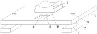
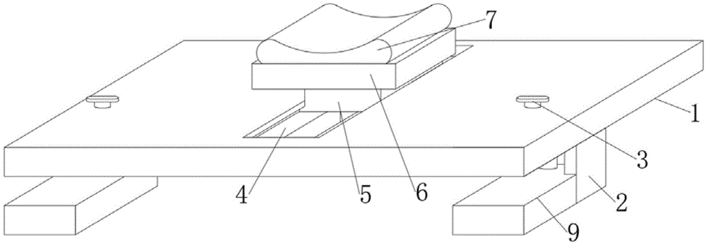
Fig. 1 is a schematic structural view of the present invention;
fig. 2 is a cross-sectional view of the present invention;
fig. 3 is a schematic view of the structure of the fixing block of the present invention;
FIG. 4 is a schematic view of the movable base of the present invention;
fig. 5 is an enlarged view of a portion a of fig. 2 according to the present invention.
Description of reference numerals:
1. a fixing plate; 2. a fixed block; 3. fixing the bolt; 4. a chute; 5. a movable seat; 6. a sliding seat; 7. a headrest; 8. a moving groove; 9. a clamping block; 10. a first rack; 11. a first sliding groove; 12. a push rod; 13. a spring; 14. a first link; 15. a first rack block; 16. a second rack; 17. a second link; 18. a second sliding groove; 19. a second rack block; 20. and a third sliding groove.
Detailed Description
In order to make the technical solution of the present invention better understood by those skilled in the art, the present invention will be further described in detail with reference to the accompanying drawings.
The utility model provides a head skin preparation device for neurosurgery, as shown in figures 1-5, comprising a fixing plate 1, wherein the top end of the fixing plate 1 is provided with a sliding groove 4, the bottom end of the inner wall of the sliding groove 4 is fixedly connected with a second rack 16, the inner wall of the sliding groove 4 is slidably connected with a movable seat 5, the inner wall of the movable seat 5 is slidably connected with a sliding seat 6, one side of the sliding seat 6 is fixedly connected with a first rack 10, one side of the movable seat 5 is slidably connected with a push rod 12, one end of the push rod 12 is fixedly connected with a spring 13, one side of the push rod 12 is positioned inside the movable seat 5 and is provided with a first sliding groove 11, one side of the push rod 12 is positioned on the inner wall of the first sliding groove 11 and is rotated and rotated with a first connecting rod 14, one end of the first connecting rod 14 is rotatably connected with a first rack block 15, one side of the first rack block 15 is meshed with one side of the second rack 16, a second sliding groove 18 is formed in the inner wall, located on the movable seat 5, of the other side of the push rod 12, a second rack block 19 is connected to the inner wall of the second sliding groove 18 in a sliding mode, a second connecting rod 17 is connected to the other side of the push rod 12 in a rotating mode, one end of the second connecting rod 17 is connected with one end of the second rack block 19 in a rotating mode, the other end of the second rack block 19 is meshed with one end of the first rack 10, under the action of the push rod 12, the first rack block 15 and the second rack block 19, when the medical care device is used, the medical care device places the fixed plate 1 at one end of a hospital bed, the fixed bolt 3 drives the clamping block 9 to move upwards in the inner wall of the movable groove 8 by rotating the fixed bolt 3, the fixed plate 1 and the hospital bed are fixed, the position of the fixed plate 1 can be conveniently adjusted according to different patient conditions, flexibility is enhanced, the medical care device pushes the push rod 12 according to different patients, the push rod 12 drives the first rack block 15 to be separated from the contact with the second rack 16 through the first connecting rod 14, so that the moving seat 5 can be pushed to slide to a proper position on the inner wall of the sliding groove 4, meanwhile, the push rod 12 drives the second rack block 19 to be separated from the contact with the first rack 10 through the second connecting rod 17, and the sliding seat 6 can be pulled to change the height of the headrest 7, so that the headrest 7 can be conveniently adjusted in multiple directions.
Further, in the above technical solution, a third sliding groove 20 is disposed at the top end of the fixing plate 1, and a fixing bolt 3 is slidably connected to an inner wall of the third sliding groove 20, and the fixing bolt 3 is mounted on the inner wall of the third sliding groove 20, so that the fixing bolt 3 can rotate on the inner wall of the third sliding groove 20.
Further, in the above technical scheme, the bottom fixedly connected with fixed block 2 of fixed plate 1, the quantity of fixed block 2 sets up to two, and the installation of fixed block 2 to fixed plate 1 of being convenient for is fixed.
As shown in fig. 1-5: one side of fixed block 2 is equipped with shifting chute 8, the inner wall sliding connection of shifting chute 8 has fixture block 9, drives fixture block 9 and removes at the inner wall of shifting chute 8 through rotating fixing bolt 3, is convenient for fix fixed plate 1.
Further, in the above technical scheme, the outer side of one side of the fixture block 9 is matched with the inner wall of the moving groove 8, the inner wall of the fixture block 9 is matched with the outer wall of the fixing bolt 3, and the moving groove 8 limits the fixture block 9, so that the fixture block 9 is effectively limited.
Further, in the above technical scheme, the top end of the sliding seat 6 is fixedly connected with a headrest 7, the headrest 7 is fixedly connected with the sliding seat 6 through bolts, and a patient leans against the top end of the headrest 7 through the head when using, so that the head of the patient can be effectively supported.
Further, in the above technical solution, the number of the fixing bolts 3 is two, and the fixing bolts 3 are rotatably connected with the third sliding groove 20 and the fixing bolts 3 rotate on the inner wall of the third sliding groove 20, so that the fixing bolts 3 can be conveniently installed.
Further, in the above technical scheme, the number of the fixture blocks 9 is two, the number of the moving grooves 8 is two, and the two fixture blocks 9 slide on the inner wall of the moving groove 8 under the driving of the fixing bolt 3, so that the fixture blocks 9 are limited.
This practical theory of operation:
referring to the attached drawings 1-5 of the specification, medical staff push the push rod 12 according to different patients, the push rod 12 drives the first rack block 15 to be separated from the second rack 16 through the first connecting rod 14, so that the movable seat 5 can be pushed to slide to a proper position on the inner wall of the sliding groove 4, meanwhile, the push rod 12 drives the second rack block 19 to be separated from the first rack 10 through the second connecting rod 17, so that the sliding seat 6 can be pulled to change the height of the headrest 7, and the headrest 7 can be conveniently adjusted in multiple directions;
referring to the attached drawings 1-3 of the specification, under the action of the clamping block 9, when the fixing plate is used, medical staff can fix the fixing plate 1 and the sickbed by placing the fixing plate 1 at one end of the sickbed and rotating the fixing bolt 3, the fixing bolt 3 drives the clamping block 9 to move upwards on the inner wall of the moving groove 8, so that the position of the fixing plate 1 can be conveniently adjusted according to different disease conditions, and the flexibility is enhanced.
While certain exemplary embodiments of the present invention have been described above by way of illustration only, it will be apparent to those of ordinary skill in the art that the described embodiments may be modified in various different ways without departing from the spirit and scope of the present invention. Accordingly, the drawings and description are illustrative in nature and should not be construed as limiting the scope of the invention.