Transfer case, hydraulic pump electric drive system and electric loader
Technical Field
The utility model relates to a power transmission device, more specifically say, relate to a transfer case and hydraulic pump electric drive system and electronic loader.
Background
In an electric loader, a work pump, a steering pump, and a transmission pump are generally provided, and these pumps are mounted on a transfer case and connected to a plurality of output shafts of the transfer case, and an electric motor is connected to an input shaft of the transfer case, and the electric motor drives each hydraulic pump through the transfer case.
The transfer case is a fixed shaft reduction box, and a plurality of gears are arranged between an input shaft and an output shaft in the transfer case for speed reduction. The working speed of the motor is usually high, and the high speed of the motor is output from the output shaft after being reduced by the transfer case to drive each hydraulic pump.
The existing transfer case generally arranges an input gear connected with an electric motor at the bottom in the transfer case and an output gear at the upper part in the transfer case, such as a special gear box for an oil pump of an electric loader disclosed in patent document CN 210686913U.
The transfer case is a gear case, and lubricating grease for lubricating gears is stored in the transfer case. However, in the existing transfer case, the input gear is arranged at the bottom in the transfer case, and when the transfer case rotates at a high speed, the transfer case generates a violent oil stirring phenomenon, so that a large amount of energy consumption is consumed, the consumed energy consumption is converted into heat, the lubricating oil in the transfer case works at a high temperature, and the replacement period of the lubricating grease is shortened.
SUMMERY OF THE UTILITY MODEL
The to-be-solved technical problem of the utility model is that gear oil stirring generates heat serious problem in the transfer case among the current hydraulic pump electric drive system, and provides a transfer case and hydraulic pump electric drive system and electronic loader to reduce the degree that gear oil stirring generates heat in the transfer case.
The utility model discloses a realize that the technical scheme of its purpose is like: a transfer case is constructed comprising a case and a plurality of gears located in the case, wherein the gears include an input gear disposed at an upper portion in the case, at least two output gears disposed at a lower portion in the case, and a geared connection from the input gear to the output gears. The utility model discloses in, input gear is located the box upper portion, and its position height is higher than the liquid level of the lubricant of bottom in the box, and output gear is located the lower part in the box, and the submergence of a small part of toothed disc is in lubricant, and output gear arouses lubricant when rotating and lubricates each rotatable parts in the box. Because the output gear is relative with the input gear, its rotational speed reduces through the speed reduction, and the output gear reduces with the oil mixing impact degree of bottom lubricating oil, and the energy consumption that the output gear oil mixing consumed just also reduces, and the phenomenon because of the oil mixing of lubricating oil generates heat also is improved.
In the transfer case, the gear further includes an intermediate gear, and the intermediate gear is engaged with both the input gear and the output gear. Through setting up intermediate gear, can increase the distance between input gear pivot and the output gear pivot to the transfer case can arrange motor and hydraulic pump in the same one side of transfer case when being connected with motor, hydraulic pump, thereby reduces the size of the hydraulic pump actuating system after the assembly, is convenient for arrange on the machine.
In the transfer case, the height of the position of the rotating shaft of the input gear is higher than that of the position of the intermediate gear, and the height of the position of the intermediate gear is higher than that of the position of the output gear. The intermediate gear is arranged between the input gear and the output gear at the upper position and the lower position, and under the condition of considering the size and the speed ratio of the transfer case, the distance between the rotating shaft of the input gear and the rotating shaft of the output gear can be further increased, so that the transfer case has more space for arranging and installing the motor and the hydraulic pump on the same side.
In the transfer case, the output gears are respectively a first output gear and a second output gear, and the rotating shaft position of the first output gear is higher than the rotating shaft position of the second output gear. The two output gears are arranged at different heights, so that the gear wheel disc of only one of the two output gears is immersed in the lubricating oil, and the energy consumed by oil stirring impact between the gear and the lubricating oil at the bottom of the box body in the rotation process of the gear is further reduced.
In the transfer case, the top of the case body is provided with a respirator, the bottom of the case body is provided with an oil discharge hole, and a plug is installed in the oil discharge hole. When the temperature inside the transfer case changes, the air inside the transfer case expands or contracts, the respirator enables the inner cavity of the transfer case to be communicated with the outside, the pressure inside and outside the transfer case is kept balanced, and oil leakage at the rotating shaft of the input gear or the rotating shaft of the output gear caused by the fact that the pressure inside the transfer case is higher than the pressure outside is avoided. The oil discharge port is used for discharging the internal oil when the lubricating oil is maintained and replaced for the separation box.
In the transfer case, the gear wheel disc and the rotating shaft of each gear are of an integrated structure, and two ends of the rotating shaft of each gear are rotatably connected with the case body through bearings; the box body is provided with a box body, the box body is provided with a plurality of output gears, the box body is provided with a plurality of transmission holes, and the transmission holes are coaxially communicated with the shaft holes. When the transfer case is connected with the motor and the hydraulic pump, the end part of the rotating shaft of the motor and the end part of the rotating shaft of the hydraulic pump penetrate through corresponding transmission holes on the transfer case shell and are inserted into the shaft hole of the rotating shaft of the input gear and the shaft hole of the rotating shaft of the output gear, so that the connection between the motor and the hydraulic pump and the input gear and the output gear is realized, and meanwhile, the shell of the motor and the shell of the hydraulic pump can be fixedly connected with the box body of the transfer case, so that the electric driving system of the hydraulic pump after assembly is compact in size and convenient to arrange on a machine.
In the transfer case, the speed ratio of the input gear and the output gear is 1.8-2.2, and the speed ratio of the transfer case is set in the range, so that the motor can work in a high-efficiency rotating speed region 4000 RPM.
The utility model discloses a realize that the technical scheme of its purpose is like: the electric drive system of the hydraulic pump is constructed, the electric drive system comprises an electric motor and at least two hydraulic pumps, and is characterized by further comprising the transfer case, the electric motor and the hydraulic pumps are fixedly arranged on a box body of the transfer case, a rotating shaft of the input gear is connected with an output shaft of the electric motor, and a rotating shaft of the output gear is connected with a rotating shaft of the hydraulic pumps. Further, the electric motor and the hydraulic pump are fixed to the same side of the transfer case.
The utility model discloses a realize that the technical scheme of its purpose is like: an electric loader is constructed that is characterized by having the aforementioned hydraulic pump electric drive system.
Compared with the prior art, the utility model discloses in, high-speed pivoted input gear is located box inner upper portion, breaks away from the lubricating oil liquid of bottom in the box, and relative low-speed rotation output gear is located box inner lower part, and output gear reduces with the oil stirring impact degree of bottom lubricating oil liquid, and the energy consumption that the oil stirring consumed just also reduces, and lubricating oil liquid phenomenon of generating heat is improved.
Drawings
Fig. 1 is a transmission schematic diagram of an electric drive system of a middle hydraulic pump of the present invention.
Fig. 2 is a rotary sectional view of the transfer case of the present invention.
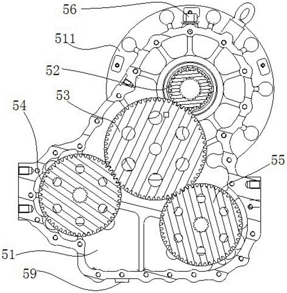
Fig. 3 is a cross-sectional view of the transfer case of the present invention.
Fig. 4 is an axial view of the electric drive system of the hydraulic pump of the present invention.
Part names and serial numbers in the figure:
the electric motor 10, the variable speed pump 20, the working pump 30, the steering pump 40, the transfer case 50, the case body 51, the output gear 52, the intermediate gear 53, the first output gear 54, the second output gear 55, the breather 56, the bearing 58 and the oil discharge port 59.
Detailed Description
The following description of the embodiments refers to the accompanying drawings.
As shown in fig. 1 and 4, the hydraulic pump electric drive system in the present embodiment is a hydraulic pump electric drive system of a loader. The system comprises an electric motor 10, a transfer case 50, a variable speed pump 20, a working pump 30 and a steering pump 40, wherein the variable speed pump 20 and the working pump 30 are coaxially arranged and combined together to work in a coaxial driving mode.
As shown in fig. 2 and 3, the transfer case 50 includes a case 51, an input gear 52 provided in the case 51, an intermediate gear 53, a first output gear 54, and a second output gear 55. Each gear is a structure integrating a rotating shaft and a gear disc, and the two ends of the rotating shaft of each gear are rotatably connected to the box body 51 of the transfer case through bearings 58.
In the transfer case 50, the input gear 52 is in gear engagement with the intermediate shaft gear 53, the intermediate gear 53 is simultaneously in gear engagement with the first output gear 54 and the second output gear 55, the speed ratio from the input gear 52 to the output gear in the transfer case is 1.95, and in specific implementation, the speed ratio can be designed to be 1.8-2.2 according to requirements, so that the motor 10 is ensured to work in a high-efficiency rotating speed region 4000 RPM.
The input gear 52 is located at the upper part in the case 51, and the output gear is located at the lower part in the case, wherein the input gear 52 is located at a higher height than the intermediate gear, and the intermediate gear 53 is located at a higher height than the first output gear 54 and the second output gear 55, wherein the first output gear 54 is located at a higher height than the second output gear 55. In the box body, part of the gear disc of the second output gear 55 is immersed in the lubricating oil at the bottom of the box body, and the heights of the gear discs of other gears are all higher than the liquid level of the lubricating oil.
As shown in fig. 2, shaft holes are provided in the rotating shafts of the input gear 52, the first output gear 54, and the second output gear 55, and internal splines are provided in the shaft holes. The housing 51 is provided with transmission holes corresponding to the shaft holes of the input gear 52, the first output gear 54, and the second output gear 55.
As shown in fig. 3, a breather 56 is provided at the top of the tank 51, an oil drain port 59 is provided at the bottom of the tank 51, and a plug is mounted in the oil drain port 59.
As shown in fig. 4, the electric motor 10 is fixedly mounted on the case body 51 via a motor fitting flange 511 on the transfer case 50, wherein the end of the rotating shaft of the electric motor 10 is inserted into the shaft hole of the rotating shaft of the input gear 52, and is splined with the input gear 52. The working pump 30 and the steering pump 40 are both fixedly arranged on the box body 51 of the transfer case, the shell of the working pump 30 is fixedly connected with the transfer case 51, and the rotating shaft of the working pump 30 is inserted in the shaft hole of the rotating shaft of the first output gear 54 and is in spline connection with the first output gear 54. The shell of the steering pump 40 is fixed on the box body 51 of the transfer case, and the tail end of the rotating shaft of the steering pump 40 is inserted into the shaft hole of the rotating shaft of the second output gear 55 and connected with the second output gear 55 through a spline.
In the present embodiment, the intermediate gear 53 is disposed between the input gear 52 and the two output gears, so that the distance between the rotating shaft of the input gear 52 and the output gears is increased, and thus, there is enough space on the side of the transfer case 50 to dispose the electric motor 10 and the two hydraulic pumps on the same side of the transfer case 50, so that the length of the electric drive system of the hydraulic pumps after assembly is short, and the arrangement on the loader is convenient.
In the present embodiment, each gear is a cylindrical gear, and may be straight gear or helical gear. The gears are arranged on the same plane, so that the thickness of the transfer case is smaller, and the motor and the hydraulic pump are arranged on one side of the transfer case 50, so that the total length of the transfer case is still shorter, and the transfer case is convenient to arrange.
In this embodiment, the input gear 52 is disposed at an upper portion in the housing 51, the second output gear 55 is disposed at a lower portion in the housing, only a gear disc of the second output gear 55 is partially immersed in the lubricating oil in the housing, and when the gears rotate, the second output gear excites the lubricating oil to lubricate the rotating components in the housing. Because the second output gear is decelerated by the intermediate gear, the rotating speed of the second output gear is greatly reduced, and the oil stirring impact of the second output gear is weakened, so that the energy consumed by the transfer case in the transmission process is reduced, and the heating of lubricating oil is also reduced.