Fixing device for manufacturing aluminum alloy hub
Technical Field
The utility model relates to a wheel hub makes technical field, especially relates to a fixing device for making aluminum alloy wheel hub.
Background
The wheel hub is a drum-shaped wheel rim, namely a part with the inner contour of the tire used for supporting the tire and the center assembled on a shaft, the common wheel hub is a steel wheel hub and an aluminum alloy wheel hub, and the steel wheel hub has high strength and is commonly used for large trucks; but steel wheel hub quality is heavy, and the appearance is single, is not conform to present low carbon, fashion's theory, is being replaced by aluminum alloy wheel hub gradually, and in wheel hub's manufacturing process, fashioned preliminary working wheel hub need be fixed centre gripping through fixed equipment, then conveniently carries out following fine processing to wheel hub.
However, the hub fixing device is often inconvenient to adjust and control during operation, and is easy to clamp and unstable during fixing, the hub is easy to loosen, and the hub is easy to slip off from the fixing device due to the appearance shape of the hub during the processing operation.
Therefore, it is necessary to provide a new fixing device for manufacturing aluminum alloy wheel hub to solve the above technical problems.
SUMMERY OF THE UTILITY MODEL
The utility model provides a technical problem provide a convenient to use, be convenient for fix the hub comprehensively, guarantee the fixed stability of wheel hub's fixing device for making aluminum alloy wheel hub.
In order to solve the above technical problem, the utility model provides a fixing device for making aluminum alloy wheel hub includes: a bottom plate; the pad connecting block is fixedly arranged at the top of the bottom plate; the arc-shaped block is fixedly arranged at the top of the cushion connecting block; the two clamping arc blocks are rotatably arranged on the arc block; the wheel hub is arranged on the arc-shaped blocks, and the two clamping arc blocks are matched with the wheel hub; the two welding fixed blocks are respectively and fixedly arranged on the corresponding clamping arc blocks; the two side connecting blocks are respectively and fixedly arranged on one side of the corresponding welding block; the two connecting pipes are respectively hinged on the corresponding side connecting blocks; the two supporting plates are fixedly arranged at the top of the bottom plate and are respectively positioned at two sides of the arc-shaped block; the middle connecting plate block is fixedly arranged between the two supporting plates; the threaded cross rod is installed between the two supporting plates in a threaded manner; the motor is arranged on one side of the corresponding supporting plate, and an output shaft of the motor is fixedly connected with one end of the threaded cross rod; the two moving blocks are installed on the threaded cross rod in a threaded mode, and are hinged to one end, far away from the side connecting block, of the corresponding connecting pipe respectively.
Preferably, two sections of external threads with opposite rotation directions are arranged on the threaded cross rod, internal threads are arranged on the two moving blocks, and the two moving blocks are in threaded connection with the threaded cross rod.
Preferably, rolling balls are inlaid at the tops of the two moving blocks, and the two rolling balls are in rolling contact with the bottom of the middle connecting plate block.
Preferably, the arc-shaped block is provided with two device grooves, a bearing pipe is fixedly arranged between the inner walls of the two sides of the device grooves, and the bearing pipe is in rotating contact with the clamping arc block.
Preferably, the two supporting plates are provided with circular holes, the inner walls of the circular holes are fixedly provided with the switching bearings, and the inner rings of the switching bearings are fixedly sleeved on the threaded cross rod.
Preferably, a supporting cushion block is fixedly installed on one side of the corresponding supporting plate, and the supporting cushion block is fixedly connected with the motor.
Compared with the prior art, the utility model provides a fixing device for making aluminum alloy wheel hub has following beneficial effect:
the utility model provides a fixing device for making aluminum alloy wheel hub thereby drives two movable blocks through the electric drive of motor and moves, adjusts the position of locating of two clamping arc pieces to the convenience is fixed wheel hub, guarantees the fixed stable comprehensiveness of wheel hub.
Drawings
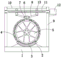
Fig. 1 is a schematic structural view of a preferred embodiment of a fixing device for manufacturing an aluminum alloy wheel hub according to the present invention;
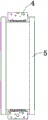
FIG. 2 is an assembly view of the clamping arc block and the hub of the present invention;
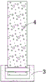
fig. 3 is an assembly view of the middle arc block and the clamping arc block of the present invention.
Reference numbers in the figures: 1. a bottom plate; 2. a cushion block; 3. an arc-shaped block; 4. clamping an arc block; 5. a hub; 6. welding a fixed block; 7. a bypass block; 8. connecting a connecting pipe; 9. a supporting plate; 10. a middle connecting plate block; 11. a threaded cross bar; 12. a motor; 13. moving the mass.
Detailed Description
The present invention will be further described with reference to the accompanying drawings and embodiments.
Please refer to fig. 1, fig. 2 and fig. 3, wherein fig. 1 is a schematic structural diagram of a fixing device for manufacturing an aluminum alloy hub according to a preferred embodiment of the present invention; FIG. 2 is an assembly view of the clamping arc block and the hub of the present invention; fig. 3 is an assembly view of the middle arc block and the clamping arc block of the present invention. A fixing device for manufacturing aluminum alloy wheel hub includes: a bottom plate 1; the cushion joint block 2 is fixedly arranged at the top of the bottom plate 1; the arc-shaped block 3 is fixedly arranged at the top of the pad connecting block 2; the two clamping arc blocks 4 are rotatably arranged on the arc block 3; the wheel hub 5 is arranged on the arc-shaped blocks 3, and the two clamping arc blocks 4 are matched with the wheel hub 5; the two welding fixed blocks 6 are respectively and fixedly arranged on the corresponding clamping arc blocks 4; the two side connecting blocks 7 are respectively and fixedly arranged on one side of the corresponding welding block 6; the two connecting pipes 8 are respectively hinged on the corresponding side connecting blocks 7; the two supporting plates 9 are fixedly arranged at the top of the bottom plate 1, and the two supporting plates 9 are respectively positioned at two sides of the arc-shaped block 3; the middle connecting plate block 10 is fixedly arranged between the two supporting plates 9; the threaded cross rod 11 is installed between the two supporting plates 9 in a threaded mode; the motor 12 is arranged on one side of the corresponding supporting plate 9, and an output shaft of the motor 12 is fixedly connected with one end of the threaded cross rod 11; the two moving blocks 13 are both installed on the threaded cross rod 11 in a threaded mode, and the two moving blocks 13 are hinged to one end, far away from the bypass block 7, of the corresponding connecting pipe 8 respectively.
Two sections of external threads with opposite rotation directions are arranged on the threaded cross rod 11, internal threads are arranged on the two moving blocks 13, and the two moving blocks 13 are in threaded connection with the threaded cross rod 11.
Rolling balls are inlaid at the tops of the two moving blocks 13, and the two rolling balls are in rolling contact with the bottom of the middle connecting plate block 10.
Two device grooves are formed in the arc-shaped block 3, a bearing pipe is fixedly installed between the inner walls of the two sides of each device groove, and the bearing pipe is in rotating contact with the clamping arc block 4.
Round holes are formed in the two supporting plates 9, switching bearings are fixedly mounted on the inner walls of the round holes, and the inner rings of the switching bearings are fixedly sleeved on the threaded cross rod 11.
And a supporting cushion block is fixedly arranged on one side of the corresponding supporting plate 9 and is fixedly connected with the motor 12.
The utility model provides a fixing device for making aluminum alloy wheel hub's theory of operation as follows:
when wheel hub 5 needs to be fixed, wheel hub 5 is placed on arc-shaped block 3 firstly, motor 12 is started after the placement is stable, an output shaft of motor 12 drives threaded cross rod 11 to rotate on two supporting plates 9, threaded cross rod 11 drives two moving blocks 13 to move close to each other under the influence of threads when rotating, corresponding connecting pipe 8 is pulled under the drive of two moving blocks 13, connecting pipe 8 drives clamping arc block 4 through welding block 6, two clamping arc blocks 4 are close to wheel hub 5 by taking the receiving pipe as the center of a circle until two clamping arc blocks 4 are all in contact with wheel hub 5 under the drive of two moving blocks 13, wheel hub 5 is clamped on arc-shaped block 3, and wheel hub is fixed between arc-shaped block 3 and two clamping arc blocks 4, so that wheel hub 5 is fixed.
Compared with the prior art, the utility model provides a fixing device for making aluminum alloy wheel hub has following beneficial effect:
the utility model provides a fixing device for making aluminum alloy wheel hub thereby drives two movable blocks 13 through the electric drive of motor 12 and moves, adjusts two clamping arc piece 4's position of locating to the convenience is fixed wheel hub 5, guarantees the fixed stable wholeness of wheel hub 5.
It should be noted that the device structure and the accompanying drawings of the present invention mainly describe the principle of the present invention, and in the technology of this design principle, the settings of the power mechanism, the power supply system, the control system, etc. of the device are not completely described, and the details of the power mechanism, the power supply system, and the control system can be clearly known on the premise that those skilled in the art understand the principle of the present invention.
The above only is the embodiment of the present invention, not limiting the scope of the present invention, all the equivalent structures or equivalent processes of the present invention are used in the specification and the attached drawings, or directly or indirectly applied to other related technical fields, and the same principle is included in the protection scope of the present invention.