CN214351381U - Automatic deburring device after processing of axle screw thread position milling flutes - Google Patents
Automatic deburring device after processing of axle screw thread position milling flutes Download PDFInfo
- Publication number
- CN214351381U CN214351381U CN202023080712.9U CN202023080712U CN214351381U CN 214351381 U CN214351381 U CN 214351381U CN 202023080712 U CN202023080712 U CN 202023080712U CN 214351381 U CN214351381 U CN 214351381U
- Authority
- CN
- China
- Prior art keywords
- deburring device
- axle
- linear guide
- automatic deburring
- automatic
- Prior art date
- Legal status (The legal status is an assumption and is not a legal conclusion. Google has not performed a legal analysis and makes no representation as to the accuracy of the status listed.)
- Expired - Fee Related
Links
- 238000003801 milling Methods 0.000 title claims abstract description 20
- 230000007246 mechanism Effects 0.000 claims abstract description 20
- 230000000149 penetrating effect Effects 0.000 claims description 4
- 230000006835 compression Effects 0.000 claims description 3
- 238000007906 compression Methods 0.000 claims description 3
- 238000003754 machining Methods 0.000 claims description 3
- 230000001360 synchronised effect Effects 0.000 claims description 3
- 238000000034 method Methods 0.000 abstract description 8
- 230000008569 process Effects 0.000 abstract description 7
- 230000009471 action Effects 0.000 abstract description 4
- 238000004519 manufacturing process Methods 0.000 abstract description 4
- 230000000694 effects Effects 0.000 abstract description 2
- 238000005498 polishing Methods 0.000 description 3
- 230000033764 rhythmic process Effects 0.000 description 2
- 229910000831 Steel Inorganic materials 0.000 description 1
- 230000008901 benefit Effects 0.000 description 1
- 238000004140 cleaning Methods 0.000 description 1
- 238000010586 diagram Methods 0.000 description 1
- 238000000227 grinding Methods 0.000 description 1
- 239000000463 material Substances 0.000 description 1
- 238000012986 modification Methods 0.000 description 1
- 230000004048 modification Effects 0.000 description 1
- 239000010959 steel Substances 0.000 description 1
- 238000006467 substitution reaction Methods 0.000 description 1
- 238000003466 welding Methods 0.000 description 1
Images


Landscapes
- Milling Processes (AREA)
Abstract
The utility model provides an automatic deburring device after processing of axle screw thread position milling flutes, including the workstation, lay linear guide on the workstation, install first slider on linear guide, set up deburring mechanism and the power device who drives deburring mechanism on first slider, deburring mechanism include top, rotation axis and annular threading die. The utility model provides an automatic deburring device utilizes annular threading die to lean on axle screw thread terminal surface tightly under the spring force effect, and the rotation axis action drives annular threading die precession, gets rid of the burr in the precession process, and the rotation axis reversal after target in place withdraws from threading die, and both sides cylinder pull back the top can, and the whole process does not need manual operation, has effectively reduced workman intensity of labour, has saved the human cost; the off-line operation is avoided, and the processing beat of an automatic production line is matched; the consistency of the product is ensured, and the product quality is improved.
Description
Technical Field
The utility model belongs to the technical field of car axle processing equipment, especially, relate to an automatic deburring device after axle screw thread position milling flutes processing.
Background
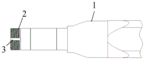
The existing automobile axle processing gradually develops to automatic and unmanned processing, wherein burrs can be generated during groove milling at the thread part of the axle, as shown in fig. 1, one end of the axle 1 is provided with a thread 2, and the thread 2 can generate burrs 3 through the groove milling. If the burrs exist, the requirements of the next process can not be met, and the burrs need to be cleaned.
At present, the manual grinding and cleaning are basically carried out, and the following problems and disadvantages mainly exist: 1. the labor intensity of workers is high; 2. off-line manual polishing is not matched with the rhythm of an automatic production line; 3. the consistency of the product is poor, and the quality is not controlled well.
SUMMERY OF THE UTILITY MODEL
An object of the utility model is to provide an automatic deburring device after axle screw thread position milling flutes processing to the clearance of polishing of manual work among the solution prior art, the following shortcoming of existence: 1. the labor intensity of workers is high; 2. off-line manual polishing is not matched with the rhythm of an automatic production line; 3. the consistency of the product is poor, and the quality is not controlled well.
In order to achieve the above object, the embodiment of the present invention provides the following technical solutions:
according to the utility model discloses an automatic deburring device after processing of axle screw thread position milling flutes is provided, including the workstation, lay linear guide on the workstation, install first slider on linear guide, set up the power device of deburring mechanism and drive deburring mechanism on first slider, deburring mechanism include top, rotation axis and annular threading die, the rotation axis wear to establish on first slider, top be used for fixing a position axle screw thread portion's central point and put, and top installs the tip at the rotation axis, annular threading die be used for getting rid of the burr after the processing of axle screw thread position milling flutes, and annular threading die installs on top, power device can drive the rotation axis and rotate to can make first slider reciprocating motion on linear guide.
Furthermore, the power device comprises an air cylinder and a motor which are arranged on the workbench, the air cylinder can drive the first sliding block to reciprocate on the linear guide rail, and the motor can drive the rotating shaft to rotate.
Further, an output shaft of the motor is connected with the rotating shaft through a synchronous belt.
Further, the deburring mechanism further comprises at least two guide shafts arranged on the first sliding block.
Further, the at least two guide shafts are symmetrically arranged on the periphery of the center.
Further, the direction of the guide shaft is consistent with the direction of the linear guide rail.
Furthermore, the automatic deburring device for the machined axle thread part further comprises a second sliding block arranged on the linear guide rail and a supporting block arranged on the second sliding block.
Furthermore, a V-shaped groove is formed in the top of the supporting block.
Furthermore, a compression spring is arranged on the guide shaft between the annular screw die and the first sliding block in a penetrating mode.
Furthermore, two first sliding blocks, two deburring mechanisms and two power devices are symmetrically arranged on the workbench.
The embodiment of the utility model provides a have following advantage: the embodiment of the utility model provides an automatic deburring device after processing of axle screw thread position milling flutes, this automatic deburring device includes workstation, linear guide, first slider, burring mechanism and power device, burring mechanism includes top, rotation axis and annular die, and both sides cylinder action promotes the top and removes, and axle screw thread portion is tightly pushed up in the centering top, and annular die leans on axle thread terminal surface under the spring force effect, and the rotation axis action drives annular die precession forward, removes the burr in the precession process, and the rotation axis is put in place the back and is reversed, withdraws from the die, and both sides cylinder pulls back the top can, and whole process does not need manual operation, has effectively reduced workman intensity of labour, has saved the human cost; the off-line operation is avoided, and the processing beat of an automatic production line is matched; the consistency of the product is ensured, and the product quality is improved.
Drawings
In order to more clearly illustrate the embodiments of the present invention or the technical solutions in the prior art, the drawings used in the embodiments or the technical solutions in the prior art will be briefly described below, and it is obvious that the drawings in the following description are some embodiments of the present invention, and for those skilled in the art, other drawings can be obtained according to these drawings without creative efforts.
FIG. 1 is a schematic structural diagram of a burr of a threaded portion of an axle in the prior art;
fig. 2 is a front view of a left half of the automatic deburring device after groove milling processing of the axle thread part provided in embodiment 1 of the present invention;
fig. 3 is a top view of the left half of the automatic deburring device after groove milling processing of the axle thread part provided in embodiment 1 of the present invention;
description of reference numerals: 1-vehicle bridge; 2-thread; 3-burring; 4-a workbench; 5-linear guide rail; 6-a first slide block; 7-top; 8-a rotating shaft; 9-annular screw die; 10-cylinder; 11-a motor; 12-a guide shaft; 13-a second slide; 14-support block.
Detailed Description
The technical solution of the present invention will be described clearly and completely with reference to the following embodiments, and it should be understood that the described embodiments are some, but not all embodiments of the present invention. Based on the embodiments in the present invention, all other embodiments obtained by a person skilled in the art without creative work belong to the protection scope of the present invention.
In the description of the present invention, it is to be understood that the terms "center", "longitudinal", "lateral", "length", "width", "thickness", "upper", "lower", "front", "rear", "left", "right", "vertical", "horizontal", "top", "bottom", "inner", "outer", "clockwise", "counterclockwise", and the like indicate orientations or positional relationships based on the orientations or positional relationships shown in the drawings, and are only for convenience of description and to simplify the description, but do not indicate or imply that the device or element referred to must have a particular orientation, be constructed and operated in a particular orientation, and therefore should not be construed as limiting the present invention.
Furthermore, the terms "first", "second" and "first" are used for descriptive purposes only and are not to be construed as indicating or implying relative importance or implicitly indicating the number of technical features indicated. Thus, features defined as "first", "second", may explicitly or implicitly include one or more of the described features. In the description of the present invention, "a plurality" means two or more unless specifically limited otherwise. Furthermore, the terms "mounted," "connected," and "connected" are to be construed broadly and may, for example, be fixedly connected, detachably connected, or integrally connected; can be mechanically or electrically connected; they may be connected directly or indirectly through intervening media, or they may be interconnected between two elements. The specific meaning of the above terms in the present invention can be understood in specific cases to those skilled in the art.
Example 1
As shown in fig. 2 and fig. 3, the embodiment provides an automatic deburring device after groove milling of the axle thread part, which comprises a workbench 4, a linear guide rail 5 laid on the workbench 4, a first slide block 6 mounted on the linear guide rail 5, a deburring mechanism arranged on the first slide block 6, and a power device for driving the deburring mechanism, the deburring mechanism comprises a tip 7, a rotating shaft 8 and an annular threading die 9, the rotating shaft 8 is arranged on the first sliding block 6 in a penetrating mode, the tip 7 is used for positioning the center position of the threaded portion of the axle, the center 7 is arranged at the end part of the rotating shaft 8, the annular screw die 9 is used for removing burrs 3 after groove milling processing of the axle thread part, and the annular screw die 9 is arranged on the centre 7, and the power device can drive the rotating shaft 8 to rotate and can make the first sliding block 6 reciprocate on the linear guide rail 5.
Preferably, the power device comprises an air cylinder 10 and a motor 11 which are arranged on the working table 4, the air cylinder 10 can drive the first slide block 6 to reciprocate on the linear guide rail 5, and the motor 11 can drive the rotating shaft 8 to rotate.
Preferably, the output shaft of the motor 11 is connected to the rotating shaft 8 through a timing belt.
Preferably, the deburring mechanism further comprises at least two guide shafts 12 arranged on the first slider 6. The at least two guide shafts 12 are symmetrically arranged on the periphery of the center 7. The direction of the guide shaft 12 coincides with the direction of the linear guide 5.
Preferably, the automatic deburring device after the groove milling of the axle thread part further comprises a second sliding block 13 arranged on the linear guide rail 5 and a supporting block 14 arranged on the second sliding block 13. The top of the supporting block 14 is provided with a V-shaped groove, and in the specific implementation, a U-shaped groove or the like can be adopted.
Preferably, a compression spring is arranged on the guide shaft 12 between the annular screw die 9 and the first sliding block 6 in a penetrating way.
Preferably, two first sliding blocks 6, two deburring mechanisms and two power devices are symmetrically arranged on the workbench 4.
The utility model provides an automatic deburring device's application method behind axle screw thread position milling flutes processing, including following step: comprises welding steel material into a work table 4, and then forming by finish machining; two cylinders 10 and two motors 11 are symmetrically installed on a common working table 4, the center position of a threaded portion of an axle is located by using a tip 7, the robot places the axle 1 after groove milling on a V-shaped supporting block 14, the cylinders 10 on two sides act to push the tip 7 to move, the axle 1 is tightly pressed by the tip in a centering manner, an annular die 9 abuts against the end face of a thread 2 of the axle 1 under the action of spring force, the motor 11 drives a rotating shaft 8 to act through a synchronous belt, the annular die 9 is screwed forward, burrs 3 are removed in the screwing-in process, the rotating shaft 8 is reversed after the rotating shaft is in place, the annular die 9 is withdrawn, the cylinders 10 on two sides pull the tip 7 back, the axle 1 is placed on the V-shaped supporting block 14, and the robot is waited to grab a next process.
Finally, it should be noted that: the above embodiments are only used to illustrate the technical solution of the present invention, and not to limit the same; although the present invention has been described in detail with reference to the foregoing embodiments, it should be understood by those skilled in the art that: the technical solutions described in the foregoing embodiments may still be modified, or some or all of the technical features may be equivalently replaced; such modifications and substitutions do not depart from the spirit and scope of the present invention.
Claims (10)
1. The utility model provides an automatic deburring device after axle screw thread position milling flutes processing which characterized in that: comprises a workbench, a linear guide rail paved on the workbench, a first slide block arranged on the linear guide rail, a deburring mechanism arranged on the first slide block, and a power device for driving the deburring mechanism,
the deburring mechanism comprises a tip, a rotating shaft and an annular die, the rotating shaft penetrates through the first sliding block, the tip is used for positioning the center of the axle thread part, the tip is installed at the end part of the rotating shaft, the annular die is used for removing burrs after groove milling machining of the axle thread part, the annular die is installed on the tip, and the power device can drive the rotating shaft to rotate and can enable the first sliding block to move on the linear guide rail in a reciprocating mode.
2. The automatic deburring device for the milled grooves of the axle thread parts according to claim 1 is characterized in that: the power device comprises an air cylinder and a motor which are arranged on the workbench, the air cylinder can drive the first sliding block to reciprocate on the linear guide rail, and the motor can drive the rotating shaft to rotate.
3. The automatic deburring device for the milled grooves of the axle thread parts according to claim 2 is characterized in that: the output shaft of the motor is connected with the rotating shaft through a synchronous belt.
4. The automatic deburring device for the milled grooves of the axle thread parts according to claim 1 is characterized in that: the deburring mechanism further comprises at least two guide shafts arranged on the first sliding block.
5. The automatic deburring device for the milled grooves of the axle thread parts according to claim 4 is characterized in that: the at least two guide shafts are symmetrically arranged on the periphery of the tip.
6. The automatic deburring device for the vehicle axle thread part after groove milling machining according to claim 4 or 5 is characterized in that: the direction of the guide shaft is consistent with that of the linear guide rail.
7. The automatic deburring device for the milled grooves of the axle thread parts according to claim 1 is characterized in that: the device also comprises a second sliding block arranged on the linear guide rail and a supporting block arranged on the second sliding block.
8. The automatic deburring device for the milled grooves of the axle thread parts according to claim 7 is characterized in that: and a V-shaped groove is formed in the top of the supporting block.
9. The automatic deburring device for the milled grooves of the axle thread parts according to claim 1 is characterized in that: and a compression spring is arranged on the guide shaft between the annular screw die and the first sliding block in a penetrating manner.
10. The automatic deburring device for the milled grooves of the axle thread parts according to claim 1 is characterized in that: two first sliding blocks, two deburring mechanisms and two power devices are symmetrically arranged on the workbench.
Priority Applications (1)
| Application Number | Priority Date | Filing Date | Title |
|---|---|---|---|
| CN202023080712.9U CN214351381U (en) | 2020-12-18 | 2020-12-18 | Automatic deburring device after processing of axle screw thread position milling flutes |
Applications Claiming Priority (1)
| Application Number | Priority Date | Filing Date | Title |
|---|---|---|---|
| CN202023080712.9U CN214351381U (en) | 2020-12-18 | 2020-12-18 | Automatic deburring device after processing of axle screw thread position milling flutes |
Publications (1)
| Publication Number | Publication Date |
|---|---|
| CN214351381U true CN214351381U (en) | 2021-10-08 |
Family
ID=77986029
Family Applications (1)
| Application Number | Title | Priority Date | Filing Date |
|---|---|---|---|
| CN202023080712.9U Expired - Fee Related CN214351381U (en) | 2020-12-18 | 2020-12-18 | Automatic deburring device after processing of axle screw thread position milling flutes |
Country Status (1)
| Country | Link |
|---|---|
| CN (1) | CN214351381U (en) |
Cited By (1)
| Publication number | Priority date | Publication date | Assignee | Title |
|---|---|---|---|---|
| CN112548746A (en) * | 2020-12-18 | 2021-03-26 | 河南凤宝重工科技有限公司 | Automatic deburring device after processing of axle screw thread position milling flutes |
-
2020
- 2020-12-18 CN CN202023080712.9U patent/CN214351381U/en not_active Expired - Fee Related
Cited By (1)
| Publication number | Priority date | Publication date | Assignee | Title |
|---|---|---|---|---|
| CN112548746A (en) * | 2020-12-18 | 2021-03-26 | 河南凤宝重工科技有限公司 | Automatic deburring device after processing of axle screw thread position milling flutes |
Similar Documents
| Publication | Publication Date | Title |
|---|---|---|
| CN112548746A (en) | Automatic deburring device after processing of axle screw thread position milling flutes | |
| CN211680903U (en) | Milling and welding synchronous integrated friction stir welding equipment | |
| CN116900376B (en) | Alloy steel casting blank milling equipment | |
| CN210548342U (en) | Electric bicycle frame processing is with milling equipment | |
| CN207953391U (en) | A kind of aluminium sheet wire drawing polishing all-in-one machine | |
| CN110524360B (en) | Synchronous deburring device for inside and outside of pipe orifice of forged piece | |
| CN204075238U (en) | A kind of rod material automatic feeding continuous turning device | |
| CN212071374U (en) | Environment-friendly grinding device based on high frequency welded tube processing usefulness | |
| CN214054639U (en) | Plate aluminum profile machining and polishing device | |
| CN216706176U (en) | Deburring equipment | |
| CN212371818U (en) | Bending machine for processing automobile return air grid aluminum profile | |
| CN205111493U (en) | External splines burring device | |
| CN219234897U (en) | Hairbrush polishing equipment | |
| CN217860431U (en) | Burr-removing and grinding device for end face of copper bar | |
| CN116000996B (en) | Large PE pipe cutting machine | |
| CN215146682U (en) | Crankshaft end milling and end face punching structure with center holes in two ends | |
| CN109048570A (en) | Surface burr treatment device for die manufacturing | |
| CN214162207U (en) | Machine tool workpiece clamping mechanism | |
| CN212600776U (en) | Engine nozzle deburring device | |
| CN219310891U (en) | Metal deburring machine | |
| CN214684300U (en) | Turning device | |
| CN105750667B (en) | A kind of arrangement for grinding of screw tool tooth form | |
| CN223130375U (en) | Grinding head tool and photovoltaic glass processing equipment | |
| CN214213396U (en) | Grinding shaft for honing main bearing hole of engine cylinder body | |
| CN215036051U (en) | Two-way flash removing equipment for water-cooled machine shell |
Legal Events
| Date | Code | Title | Description |
|---|---|---|---|
| GR01 | Patent grant | ||
| GR01 | Patent grant | ||
| CF01 | Termination of patent right due to non-payment of annual fee | ||
| CF01 | Termination of patent right due to non-payment of annual fee |
Granted publication date: 20211008 |