CN214320407U - Recycling equipment for waste mechanical electronic parts - Google Patents
Recycling equipment for waste mechanical electronic parts Download PDFInfo
- Publication number
- CN214320407U CN214320407U CN202022980378.6U CN202022980378U CN214320407U CN 214320407 U CN214320407 U CN 214320407U CN 202022980378 U CN202022980378 U CN 202022980378U CN 214320407 U CN214320407 U CN 214320407U
- Authority
- CN
- China
- Prior art keywords
- separation
- shell
- box
- grinding
- electronic parts
- Prior art date
- Legal status (The legal status is an assumption and is not a legal conclusion. Google has not performed a legal analysis and makes no representation as to the accuracy of the status listed.)
- Expired - Fee Related
Links
- 239000002699 waste material Substances 0.000 title claims abstract description 16
- 238000004064 recycling Methods 0.000 title claims description 9
- 238000000926 separation method Methods 0.000 claims abstract description 39
- 238000011084 recovery Methods 0.000 claims abstract description 16
- 238000009434 installation Methods 0.000 claims abstract description 7
- 239000000463 material Substances 0.000 claims description 11
- 238000007599 discharging Methods 0.000 claims 1
- 238000010298 pulverizing process Methods 0.000 abstract description 8
- 238000012216 screening Methods 0.000 abstract description 3
- 238000000151 deposition Methods 0.000 description 2
- 230000000694 effects Effects 0.000 description 2
- 238000000034 method Methods 0.000 description 2
- 230000004075 alteration Effects 0.000 description 1
- 230000009286 beneficial effect Effects 0.000 description 1
- 238000003754 machining Methods 0.000 description 1
- 238000012986 modification Methods 0.000 description 1
- 230000004048 modification Effects 0.000 description 1
- 239000007921 spray Substances 0.000 description 1
- 238000006467 substitution reaction Methods 0.000 description 1
Images


Landscapes
- Processing Of Solid Wastes (AREA)
Abstract
The utility model discloses a waste mechanical electronic part recovery device, which belongs to the technical field of mechanical part processing, and comprises a shell and a separation box, wherein the separation box is arranged in the shell and comprises a separation shell, a conveyer belt, separation holes, a second motor, an installation rod, a conical feed inlet and a sliding plate, the conveyer belt is arranged in the separation shell, and the separation holes are formed in the surface of the conveyer belt; through setting up the separator box, can be quick carry out recycle to the spare part after pulverizing, through setting up the screening net, can separate the spare part after pulverizing, make the spare part of different shapes size pack into different respectively and deposit the case to reduce the work load of staff's separation, also improved work efficiency, through setting up the air pump, can effectually clear up on the pole that pulverizes after having smashed, improve the stability that the spare part was retrieved, make it not extravagant resource.
Description
Technical Field
The utility model relates to a machine parts machining field specifically is an abandonment mechano-electronic spare part recovery plant.
Background
A machine element (also called a machine part) is a basic element that constitutes a machine and is a non-detachable single piece that constitutes both the machine and the machine. The mechanical parts are a subject of researching and designing mechanical basic parts in various devices and are also a general term of parts and components.
At present, mechanical electronic parts can be recovered after being used up, but in the process of crushing and recovering, because the friction temperature is too high, parts are easy to stick on the crushing rod, so that the resource waste is caused, and the inconvenience is caused when the crushing box is cleaned, and after being crushed, the parts are generally recovered manually, so that a large amount of time is consumed, the workload of workers is increased, and the efficiency is reduced.
SUMMERY OF THE UTILITY MODEL
An object of the utility model is to provide an abandonment mechano-electronic spare part recovery plant, through setting up the separator box, can be quick carry out recycle to the spare part after pulverizing, through setting up the screening net, can be to the spare part after pulverizing, separate, make the spare part of different shapes size pack into the different case of depositing respectively, thereby reduce the work load of staff's separation, and also improved work efficiency, through setting up the air pump, can effectually clear up on the pulverizing pole after pulverizing, improve the stability that the spare part was retrieved, make it not extravagant resource.
To solve the problems set forth in the background art described above.
In order to achieve the above object, the utility model provides a following technical scheme: the utility model provides an abandonment machinery electronic components recovery plant, includes casing, separator box, the inside of casing is equipped with the separator box, the separator box includes separating shell, conveyer belt, separation hole, second motor, installation pole, toper feed inlet, sliding material board, the inside of separating shell is equipped with the conveyer belt, the separation hole is seted up on the surface of conveyer belt, the bottom both ends fixed connection installation pole of separating shell, the fixed second motor of right-hand member of separating shell, the bottom center installation toper discharge gate of separating shell, the sliding material board is connected in the left side of separating shell, the inside left and right sides installation air pump of casing, the right side swing joint outlet duct of air pump, the gas outlet is connected to the other end of outlet duct, the gas outlet is installed on crushing box.
Preferably, a crushing box is arranged above the inside of the shell, a feed inlet is arranged in the center of the top of the crushing box, and a discharge pipe is arranged in the center of the bottom of the crushing box.
Preferably, the left end of the interior of the crushing box is provided with a first motor, and an output shaft of the first motor is movably connected with the rotating shaft.
Preferably, the other end of the rotating shaft is welded with a grinding rod, and the surface of the grinding rod is provided with a grinding blade.
Preferably, the other end of the grinding rod is movably connected with the inside of the bearing, and the bearing is embedded at the right end of the inside of the grinding box.
Preferably, the other end of the material sliding plate is connected with a first recovery box, and the other end of the conical material outlet is connected with a second recovery box.
Preferably, the two ends of the bottom of the shell are fixedly connected with the supporting legs.
Compared with the prior art, the beneficial effects of the utility model are that:
compared with the prior art, the utility model discloses a set up the separator box, can be quick carry out recycle to the spare part after pulverizing, through setting up the screening net, can separate the spare part after pulverizing, make the spare part of different shapes size pack into the different case of depositing respectively to reduce the work load of staff's separation, also improved work efficiency, through setting up the air pump, can effectually clear up on the pole that pulverizes after having pulverize, improve the stability of spare part recovery, make it not extravagant resource.
Drawings
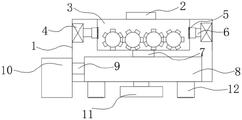
FIG. 1 is a schematic view of the recycling apparatus of the present invention;
FIG. 2 is a schematic structural view of a cross-sectional view of the crushing box of the present invention;
fig. 3 is a schematic view of the structure of the separation box of the present invention.
In the figure: 1. a housing; 2. a feed inlet; 3. a grinding box; 4. an air pump; 5. an air outlet; 6. an air outlet pipe; 7. a discharge pipe; 8. a separation tank; 9. a material sliding plate; 10. a first recovery tank; 11. a second recovery tank; 12. a support leg; 13. a first motor; 14. a rotating shaft; 15. grinding the rods; 16. a grinding blade; 17. a bearing; 18. a conical feed inlet; 19. separating the shell; 20. a conveyor belt; 21. a separation well; 22. a second motor; 23. mounting a rod; 24. a conical discharge hole.
Detailed Description
The technical solutions in the embodiments of the present invention will be described clearly and completely with reference to the accompanying drawings in the embodiments of the present invention, and it is obvious that the described embodiments are only some embodiments of the present invention, not all embodiments. Based on the embodiments in the present invention, all other embodiments obtained by a person skilled in the art without creative work belong to the protection scope of the present invention.
Referring to fig. 1 to 3, the present invention provides a technical solution: a kind of abandonment machinery electronic spare part recovery plant, including body 1, separator box 8, the inside of the body 1 has separator box 8, the separator box 8 mainly plays the role of separating after grinding the part, can raise the efficiency of the waste recovery, thus has lightened the work load of the employee, the separator box 8 includes the separation shell 19, the conveyer belt 20, the separation hole 21, the second electrical machinery 22, the mounting rod 23, the taper feed inlet 18, the material sliding plate 9, the inside of the separation shell 19 has conveyer belt 20, the conveyer belt 20 mainly plays the role of transporting and separating after grinding, the surface of the conveyer belt 20 offers the separation hole 21, the separation hole 21 mainly plays the role of making and grinding the part of different size to separate, improve the quality recovered;
the two ends of the bottom of the separation shell 19 are fixedly connected with mounting rods 23, the mounting rods 23 mainly play a role of fixedly mounting the separation shell 19, the right end of the separation shell 19 is fixedly provided with a second motor 22, the second motor 22 is started to drive the conveyer belt 20 to move, the center of the bottom of the separation shell 19 is provided with a conical discharge port 24, the conical discharge port 24 mainly enables small parts to slide down, the left side of the separation shell 19 is connected with a sliding plate 9, the sliding plate 9 mainly enables large crushed parts to slide down into the first recovery box 10, the left side and the right side of the inside of the shell 1 are provided with air pumps 4, the air pumps 4 mainly enable waste materials stained on the crushing rods 15 to blow down through the air pumps, so that resources are not wasted, the right side of the air pumps 4 is movably connected with an air outlet pipe 6, the air outlet pipe 6 mainly enables the air pumps 4 to spray out, the other end of the air outlet pipe 6 is connected with an air outlet 5 and then discharged through the air outlet 5, thereby enlarging the range to clean the periphery of the grinding box, and the air outlet 5 is arranged on the grinding box 3;
a grinding box 3 is arranged above the inside of the shell 1, the grinding box 3 mainly plays a role in processing waste mechanical parts, a feed port 2 is arranged in the center of the top of the grinding box 3, the parts are poured into the grinding box 3 through the feed port 2, a discharge pipe 7 is arranged in the center of the bottom of the grinding box 3, and the ground parts flow into a conical feed port through the discharge pipe 7;
a first motor 13 is arranged at the left end inside the crushing box 3, an output shaft of the first motor 13 is movably connected with a rotating shaft 14, a crushing rod 15 is welded at the other end of the rotating shaft 14, a crushing blade 16 is arranged on the surface of the crushing rod 15, and the first motor 13 is started to drive the crushing blade 16 on the crushing rod 15 and the opposite crushing rod to further process parts;
the other end swing joint bearing 17's of grinding pole 15 inside, bearing 17 mainly plays the effect of supporting and rotatory grinding pole 15, bearing 17 inlays at the inside right-hand member that grinds case 3, first collection box 10 is connected to the other end of flitch 9, the bold waste material is mainly retrieved to first collection box 10, second collection box 11 is connected to the other end of toper discharge gate 24, the main fritter waste machine spare part of retrieving of second collection box 11, casing 1's bottom both ends fixed connection landing leg 12, landing leg 12 mainly plays the effect of supporting this whole device.
The working principle is as follows: when the device is used, waste mechanical parts are poured into the grinding box 3 from the feeding hole 2, the grinding rods 15 on the grinding box are rotated by starting the first motor 13 to drive the rotating shaft 14 of the output end, the parts are ground by arranging the opposite grinding rods 15 to be matched with each other, the ground parts flow into the conical feeding hole 18 in the separation box 8 through the discharge pipe 7 and then enter the separation shell 19, at the moment, the second motor 22 is started to drive the conveyer belt 20 in the separation shell 19 to move, the ground parts are separated through the separation holes 21 on the separation shell, and therefore the recovery efficiency of the separated parts is improved, and the ground parts flow into respective storage positions through the sliding material plate 9 and the conical discharge hole 24.
Although embodiments of the present invention have been shown and described, it will be appreciated by those skilled in the art that changes, modifications, substitutions and alterations can be made in these embodiments without departing from the principles and spirit of the invention, the scope of which is defined in the appended claims and their equivalents.
Claims (7)
1. The utility model provides a abandonment machine electronics spare part recovery plant, includes casing (1), separator box (8), its characterized in that: the separation box (8) is arranged in the shell (1), the separation box (8) comprises a separation shell (19), a conveying belt (20), separation holes (21), a second motor (22), an installation rod (23), a conical feed inlet (18) and a material sliding plate (9), the conveying belt (20) is arranged in the separation shell (19), the separation holes (21) are formed in the surface of the conveying belt (20), the installation rod (23) is fixedly connected to the two ends of the bottom of the separation shell (19), the second motor (22) is fixed to the right end of the separation shell (19), a conical discharge outlet (24) is installed in the center of the bottom of the separation shell (19), the material sliding plate (9) is connected to the left side of the separation shell (19), air pumps (4) are installed on the left and right sides of the interior of the shell (1), an air outlet pipe (6) is movably connected to the right side of the air pumps (4), and an air outlet pipe (5) is connected to the other end of the air outlet pipe (6), the air outlet (5) is arranged on the crushing box (3).
2. The recycling apparatus for waste mechanical electronic parts according to claim 1, wherein: the grinding device is characterized in that a grinding box (3) is arranged above the inner part of the shell (1), a feeding hole (2) is formed in the center of the top of the grinding box (3), and a discharging pipe (7) is formed in the center of the bottom of the grinding box (3).
3. The recycling apparatus for waste mechanical electronic parts according to claim 2, wherein: the left end of the interior of the crushing box (3) is provided with a first motor (13), and an output shaft of the first motor (13) is movably connected with a rotating shaft (14).
4. The recycling apparatus for waste mechanical electronic parts according to claim 3, wherein: the other end of pivot (14) welds grinding rod (15), the surface mounting who grinds grinding rod (15) grinds blade (16).
5. The recycling apparatus for waste mechanical electronic parts according to claim 4, wherein: the other end of the grinding rod (15) is movably connected with the inside of the bearing (17), and the bearing (17) is embedded at the right end of the inside of the grinding box (3).
6. The recycling apparatus for waste mechanical electronic parts according to claim 1, wherein: the other end of the material sliding plate (9) is connected with a first recovery box (10), and the other end of the conical material outlet (24) is connected with a second recovery box (11).
7. The recycling apparatus for waste mechanical electronic parts according to claim 1, wherein: the two ends of the bottom of the shell (1) are fixedly connected with the supporting legs (12).
Priority Applications (1)
| Application Number | Priority Date | Filing Date | Title |
|---|---|---|---|
| CN202022980378.6U CN214320407U (en) | 2020-12-11 | 2020-12-11 | Recycling equipment for waste mechanical electronic parts |
Applications Claiming Priority (1)
| Application Number | Priority Date | Filing Date | Title |
|---|---|---|---|
| CN202022980378.6U CN214320407U (en) | 2020-12-11 | 2020-12-11 | Recycling equipment for waste mechanical electronic parts |
Publications (1)
| Publication Number | Publication Date |
|---|---|
| CN214320407U true CN214320407U (en) | 2021-10-01 |
Family
ID=77899643
Family Applications (1)
| Application Number | Title | Priority Date | Filing Date |
|---|---|---|---|
| CN202022980378.6U Expired - Fee Related CN214320407U (en) | 2020-12-11 | 2020-12-11 | Recycling equipment for waste mechanical electronic parts |
Country Status (1)
| Country | Link |
|---|---|
| CN (1) | CN214320407U (en) |
-
2020
- 2020-12-11 CN CN202022980378.6U patent/CN214320407U/en not_active Expired - Fee Related
Similar Documents
| Publication | Publication Date | Title |
|---|---|---|
| CN207578807U (en) | A kind of plastic disintegrator with dust recycling | |
| CN205925938U (en) | Waste glass smashes recovery system | |
| WO2020098707A1 (en) | Air dry sand coal sorting system | |
| CN215089703U (en) | Take diaphragm dry pole piece to handle recovery system | |
| CN212310399U (en) | Circuit board resource cleaning treatment device | |
| CN113083862A (en) | Treatment and recovery system and method for dry pole piece with diaphragm | |
| CN211099403U (en) | A coal mine pulverizer with dust removal function | |
| CN209155310U (en) | A kind of equipment for separating liquid from solid | |
| CN212331533U (en) | Environment-friendly waste plastic crushing and recycling equipment | |
| CN206483801U (en) | Electronic waste processing unit | |
| CN205217080U (en) | Vibrating device is collected to shaking table crushed aggregates | |
| CN213496317U (en) | A supply sand device in turn for 3D sand printer | |
| CN209123993U (en) | A kind of glass powder recovery system | |
| CN203491365U (en) | Recycling system for lead plaster on waste polar plate | |
| CN210474264U (en) | Building engineering waste recovery device | |
| CN113275110A (en) | Improved edible mushroom demoulding equipment | |
| CN220048989U (en) | Impurity winnowing recovery device | |
| CN208727677U (en) | A kind of aluminium-plastic panel leftover pieces shredding mechanism | |
| CN215050455U (en) | Scrap steel smelting device for resource regeneration | |
| CN210522608U (en) | Grit crushing equipment with dust removal function | |
| CN221157093U (en) | Dust suppression type iron ore crushing device | |
| CN218132118U (en) | Crushed aggregates recovery unit in aquatic products processing | |
| CN222328777U (en) | Wind-powered electricity generation blade breakage recovery unit | |
| CN221084898U (en) | A waste chip collection device in the production process of a floor scale | |
| CN223393493U (en) | Concrete grinding device |
Legal Events
| Date | Code | Title | Description |
|---|---|---|---|
| GR01 | Patent grant | ||
| GR01 | Patent grant | ||
| CF01 | Termination of patent right due to non-payment of annual fee | ||
| CF01 | Termination of patent right due to non-payment of annual fee |
Granted publication date: 20211001 |