CN214314189U - Switch cabinet equipment with good heat dissipation effect - Google Patents
Switch cabinet equipment with good heat dissipation effect Download PDFInfo
- Publication number
- CN214314189U CN214314189U CN202120611369.1U CN202120611369U CN214314189U CN 214314189 U CN214314189 U CN 214314189U CN 202120611369 U CN202120611369 U CN 202120611369U CN 214314189 U CN214314189 U CN 214314189U
- Authority
- CN
- China
- Prior art keywords
- cabinet body
- heat dissipation
- cabinet
- dust
- blocking net
- Prior art date
- Legal status (The legal status is an assumption and is not a legal conclusion. Google has not performed a legal analysis and makes no representation as to the accuracy of the status listed.)
- Active
Links
- 230000017525 heat dissipation Effects 0.000 title claims abstract description 26
- 230000000694 effects Effects 0.000 title claims abstract description 23
- 239000000428 dust Substances 0.000 claims abstract description 33
- 230000007246 mechanism Effects 0.000 claims abstract description 11
- 230000000903 blocking effect Effects 0.000 claims description 14
- 238000009434 installation Methods 0.000 claims description 10
- 238000009423 ventilation Methods 0.000 abstract description 8
- 230000005611 electricity Effects 0.000 description 3
- 238000000034 method Methods 0.000 description 3
- 238000010586 diagram Methods 0.000 description 2
- 238000012986 modification Methods 0.000 description 2
- 230000004048 modification Effects 0.000 description 2
- 238000003756 stirring Methods 0.000 description 2
- 230000032683 aging Effects 0.000 description 1
- 230000004888 barrier function Effects 0.000 description 1
- 238000007664 blowing Methods 0.000 description 1
- 230000008569 process Effects 0.000 description 1
- 238000007789 sealing Methods 0.000 description 1
Images




Landscapes
- Cooling Or The Like Of Electrical Apparatus (AREA)
Abstract
The utility model belongs to the technical field of switch cabinets, in particular to switch cabinet equipment with good heat dissipation effect, which comprises a base, wherein one side of a cabinet body is provided with an air blower, the other end of a rubber hose is connected with a cabinet door, the inner side of the cabinet door is provided with a windshield communicated with the rubber hose, the rear side of the cabinet body is provided with a ventilation opening, a ventilation dust-blocking net matched with the ventilation opening is arranged in a mounting groove in a sliding way, a spring is arranged in a step hole, the spring is fixedly connected with a T-shaped locking piece extending out of the step hole, the cabinet body is provided with a pulling mechanism matched with the T-shaped locking piece, the ventilation dust-blocking net is provided with a lock hole matched with the T-shaped locking piece, the device has simple structure and reasonable design, can uniformly dissipate heat of all electrical elements in the cabinet body, the rear side of the cabinet body is provided with the ventilation opening, the heat in the cabinet body can be well dissipated, the ventilation dust-blocking net can block the ventilation opening without affecting the heat dissipation, can prevent external dust from entering the cabinet body through the heat dissipation port and damaging electrical components.
Description
Technical Field
The utility model belongs to the technical field of the cubical switchboard, concretely relates to cubical switchboard equipment that radiating effect is good.
Background
The switch cabinet is an electrical device, the external line of the switch cabinet firstly enters a main control switch in the cabinet and then enters a branch control switch, each branch circuit is arranged according to the requirement, such as an instrument, an automatic control, a motor magnetic switch, various alternating current contactors and the like, the main function of the switch cabinet is to open, close, control and protect the electrical device in the process of generating electricity, transmitting electricity, distributing electricity and converting electric energy of an electric power system, because the electrical device or the motor magnetic switch and other instruments installed in the switch cabinet are more, after long-time work, a large amount of heat can be generated, the temperature in the switch cabinet is increased, the service life of electrical elements in the switch cabinet is easily influenced, the aging of the electrical elements is accelerated, the cost of a user is increased, and the fire disaster can be seriously caused, so that the design of the cabinet opening device with good heat dissipation effect is very necessary.
SUMMERY OF THE UTILITY MODEL
The utility model aims at: the switch cabinet equipment with the good heat dissipation effect can uniformly dissipate heat of all electrical elements in the cabinet body, the rear side of the cabinet body is provided with the ventilating opening, so that heat in the cabinet body can be well dissipated, the ventilating dust blocking net can shield the ventilating opening, and when heat dissipation is not affected, external dust can be prevented from entering the cabinet body through the radiating opening and damaging the electrical elements.
In order to realize the technical purpose, the utility model discloses a technical scheme as follows:
a switch cabinet device with good heat dissipation effect comprises a base, wherein a cabinet body is arranged on the upper side of the base, the base supports the cabinet body, a mounting frame is arranged in the cabinet body and used for mounting electric elements, a cabinet door is hinged to the front side of the cabinet body and used for sealing the cabinet body, an air blower is arranged on one side of the cabinet body, a rubber hose is arranged at an air outlet of the air blower, the other end of the rubber hose is connected with the cabinet door, a windshield communicated with the rubber hose is arranged on the inner side of the cabinet door, the air blower can blow air into the windshield, the rubber hose can ensure that the air can still be blown into the windshield after the cabinet door is closed, the windshield is provided with a plurality of air holes, the air holes can enable an air fan entering the windshield to uniformly dissipate the heat of the electric elements mounted on the mounting frame, and the rear side of the cabinet body is provided with an air vent, the ventilating opening can radiate heat in the cabinet body, a mounting groove communicated with the ventilating opening is arranged at the rear side of the cabinet body, one side of the mounting groove penetrates through the cabinet body, a ventilating dust blocking net matched with the ventilating opening is slidably assembled in the mounting groove, the ventilating dust blocking net can seal the ventilating opening, external dust is prevented from entering the cabinet body and damaging electrical elements in the cabinet body while the heat radiating and ventilating effect is not influenced, a step hole is formed in the inner wall of the outlet of the mounting groove, a spring is arranged in the step hole and fixedly connected with a T-shaped locking piece extending out of the step hole, the spring can push the T-shaped locking piece out of the step hole and is used for arranging a pulling mechanism matched with the T-shaped locking piece on the cabinet body, the pulling mechanism can pull the T-shaped locking piece into the step hole completely to compress the spring, and the ventilating dust blocking net is provided with a lock hole matched with the T-shaped locking piece, the T-shaped locking piece can be locked in the locking hole to limit and fix the breathable dust blocking net.
The pulling mechanism comprises a sliding groove which is arranged on the side wall of the cabinet body and is communicated with the step hole, the sliding groove is slidably provided with a connecting rod fixedly connected with the T-shaped locking piece, and the connecting rod extends out of the sliding groove fixedly connected with a pulling piece. With the structure, the worker can pull the pulling part to move the pulling part to one side away from the breathable dust blocking net, the pulling part drives the T-shaped locking part to be put into the step hole through the connecting rod, the spring is compressed, and after the worker loosens the pulling part, the T-shaped locking part can be ejected out of the step hole through the stretching of the spring.
The inner wall of one side of the mounting groove outlet opposite to the step hole is provided with a notch, and the breathable dust blocking net is fixedly connected with a fixing block matched with the notch. Such structure, when the cancellation to the spacing back of ventilative dust blocking net, the staff can stretch into the breach with the hand in, stir the fixed block, will breathe freely and keep off dust and net and shift out the mounting groove.
The base four corners all is equipped with the installation piece, four the installation piece all is equipped with the staple. By the structure, the switch cabinet is convenient for workers to fix on the ground.
The rubber hose is detachably and fixedly connected with the box door and the air blower. By adopting the structure, the rubber hose is convenient for workers to replace.
The air inlet of the air blower is provided with a round frame, and the round frame is in threaded connection with a dust hood. Such structure can prevent that external dust from getting into the cabinet internally through the air-blower, keeps off dust hood and circle frame threaded connection, and the staff of being convenient for changes or clears up the dust hood.
Compared with the prior art, the utility model has the following advantages:
this device simple structure, reasonable in design, can evenly dispel the heat to all electrical components of the internal portion of cabinet, cabinet body rear side is equipped with ventilative mouthful, make the heat of the internal portion of cabinet go out by fine heat dissipation, ventilative fender dirt net can shelter from ventilative mouthful, when not influencing the heat dissipation, it is internal to prevent that external dust from getting into the cabinet through the thermovent, cause the damage to electrical components, the staff is convenient for dismantle ventilative fender dirt net, clear up ventilative fender dirt net, and dismantle ventilative fender dirt net after getting off, the connecting wire of the internal rear side of staff's ventilative mouthful arrangement cabinet, the space of arrangement connecting wire has been increased, staff's work efficiency is improved.
Drawings
The present invention can be further illustrated by the non-limiting examples given in the accompanying drawings;
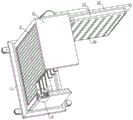
fig. 1 is a schematic structural diagram of an embodiment of the switch cabinet device with a good heat dissipation effect of the present invention;
fig. 2 is a schematic view of a partial structure of an embodiment of the switch cabinet device with a good heat dissipation effect of the present invention;
fig. 3 is a schematic view of a partial structure of an embodiment of the switch cabinet device with a good heat dissipation effect of the present invention;
fig. 4 is a schematic sectional structure diagram of an embodiment of the switch cabinet device with a good heat dissipation effect of the present invention;
FIG. 5 is an enlarged view of the structure at A in FIG. 4;
fig. 6 is a schematic structural view of a ventilating dust-blocking net of an embodiment of the switch cabinet equipment with a good heat dissipation effect of the present invention;
fig. 7 is a schematic structural view of a dust hood of an embodiment of the switchgear apparatus of the present invention, which has a good heat dissipation effect;
the main element symbols are as follows:
the dust-proof device comprises a base 1, a cabinet body 11, a mounting frame 111, a box door 12, a blower 13, a rubber hose 14, a wind shield 15, an air hole 16, an air vent 2, a mounting groove 21, an air-permeable dust-proof net 22, a step hole 23, a spring 24, a T-shaped locking piece 25, a locking hole 26, a chute 3, a connecting rod 31, a pulling piece 32, a notch 33, a fixing block 34, a mounting block 35, a fixing nail 36, a round frame 37 and a dust-proof cover 38.
Detailed Description
In order to make the present invention better understood by those skilled in the art, the technical solutions of the present invention are further described below with reference to the accompanying drawings and examples.
As shown in fig. 1-7, the switch cabinet device with good heat dissipation effect of the present invention comprises a base 1, a cabinet 11 is disposed on the upper side of the base 1, a mounting frame 111 is disposed in the cabinet 11, a cabinet door 12 is hinged on the front side of the cabinet 11, an air blower 13 is disposed on one side of the cabinet 11, a rubber hose 14 is disposed at an air outlet of the air blower 13, the other end of the rubber hose 14 is connected to the cabinet door 12, a wind shield 15 communicated with the rubber hose 14 is disposed on the inner side of the cabinet 12, the wind shield 15 is provided with a plurality of air holes 16, a vent 2 is disposed on the rear side of the cabinet 1, a mounting groove 21 communicated with the vent 2 is disposed on the rear side of the cabinet 1, one side of the mounting groove 21 penetrates through the cabinet 1, a ventilation dust-blocking net 22 matched with the vent 2 is slidably disposed in the mounting groove 21, a step hole 23 is disposed on the inner wall of an outlet of the mounting groove 21, a spring 24 is disposed in the step hole 23, the spring 24 is fixedly connected with a T-shaped locking member 25 extending out of the step hole 23, the cabinet body 11 is provided with a pulling mechanism matched with the T-shaped locking piece 25, and the breathable dust-blocking net 22 is provided with a lock hole 26 matched with the T-shaped locking piece 25.
By adopting the technical scheme of the utility model, the electrical components are installed on the installation frame 111, the blower 13 can blow wind into the windshield 15, and the wind is uniformly blown into the cabinet body 11 through the plurality of air holes 16 arranged on the windshield 15, so that the heat dissipation of the electrical components in the cabinet body 1 can be realized, and compared with the traditional method of blowing wind at one position in the cabinet body 11, the heat dissipation effect is improved; the heat in the cabinet body 11 is radiated outwards through the rear ventilating opening 2; the ventilating dust-blocking net 22 can ensure that external dust can not enter the cabinet body 11 through the ventilating opening 2 while the ventilating opening 2 can radiate heat, so that electric elements inside the cabinet body 11 are damaged; when workers need to clean the breathable dust-blocking net 22, the workers can pull the T-shaped locking piece 25 to be accommodated in the stepped hole 23 through the pulling mechanism, the spring 24 is compressed until the T-shaped locking piece 25 is moved out of the locking hole 26, the limiting of the breathable dust-blocking net 22 is cancelled, and at the moment, the workers can directly pull the breathable dust-blocking net 22 out of the mounting groove 21 to clean the breathable dust-blocking net 22; when the breathable dust-blocking net 22 needs to be installed, similarly, the T-shaped locking piece 25 is put into the stepped hole 23 through the pulling mechanism, the spring 24 is compressed, then the breathable dust-blocking net 22 is pushed into the installation groove 21 until the breathable dust-blocking net 22 is completely put into the installation groove 21, at the moment, the pulling mechanism is released, the T-shaped locking piece 25 is pushed out of the stepped hole 23 through the extension of the spring 24 and extends into the lock hole 26, and the breathable dust-blocking net 22 is limited; after the breathable dust blocking net 22 is detached, workers can arrange the connecting wires at the rear side in the cabinet body 11 through the breathable opening 2, compared with the traditional method that only the box door 12 can be opened to arrange the connecting wires, the space for arranging the connecting wires is increased, and the working efficiency of the workers is improved; this device simple structure, reasonable in design can evenly dispel the heat to the inside all electrical components of the cabinet body 11, and cabinet body 11 rear side is equipped with ventilative mouthful 2, makes the heat that cabinet body 11 is inside can be fine the heat dissipation go out, and ventilative dust blocking net 22 can shelter from ventilative mouthful 2, when not influencing the radiating, can prevent that external dust from getting into cabinet body 11 through the thermovent in, causes the damage to electrical components.
The pulling mechanism comprises a sliding chute 3 which is arranged on the side wall of the cabinet body 1 and communicated with the step hole 23, the sliding chute 3 is slidably provided with a connecting rod 31 which is fixedly connected with the T-shaped locking piece 25, and the connecting rod 31 extends out of the sliding chute 3 and is fixedly connected with a pulling piece 32. With the structure, the worker can pull the pulling part 32 to move the pulling part 32 to the side far away from the air-permeable dust-blocking net 22, the pulling part 32 drives the T-shaped locking part 25 to be accommodated in the stepped hole 23 through the connecting rod 31, the spring 24 is compressed, and after the worker loosens the pulling part 32, the T-shaped locking part 25 can be ejected out of the stepped hole 23 through the extension of the spring 24. In fact, other configurations are contemplated as the case may be, pulling T-lock 25 into stepped bore 23.
A gap 33 is arranged on the inner wall of the outlet of the mounting groove 21 opposite to the stepped hole 23, and a fixing block 34 matched with the gap 33 is fixedly connected to the air permeable dust-blocking net 22. With the structure, after the limit of the ventilating dust-blocking net 22 is cancelled, a worker can stretch a hand into the notch 33, stir the fixing block 34 and move the ventilating dust-blocking net 22 out of the mounting groove 21. In fact, other structures are also contemplated as the case may be, to facilitate the movement of the air permeable dust barrier net 22 out of the installation groove 21 by the worker.
All be equipped with installation piece 35 in the 1 four corners of base, four installation pieces 35 all are equipped with staple 36. With the structure, after the limit of the air-permeable dust blocking net 22 is cancelled, the switch cabinet can be conveniently fixed on the ground by workers. In fact, other structures can be considered according to specific situations, so that the switch cabinet can be conveniently fixed on the ground by workers.
The rubber hose 14 is detachably and fixedly connected with the box door 12 and the blower 13. With such a structure, it is convenient for the worker to replace the rubber hose 14. In fact, other configurations are contemplated as appropriate to facilitate replacement of the rubber hose 14 by a worker.
The air inlet of the blower 13 is provided with a round frame 37, and the round frame 37 is in threaded connection with a dust hood 38. With the structure, external dust can be prevented from entering the cabinet body 1 through the blower 13, and the dust hood 38 is in threaded connection with the circular frame 37, so that workers can replace or clean the dust hood 38 conveniently. In fact, other structures are also contemplated, as the case may be, and external dust is introduced into the cabinet 1 by the blower 13.
The above embodiments are merely illustrative of the principles and effects of the present invention, and are not to be construed as limiting the invention. Modifications and variations can be made to the above-described embodiments by those skilled in the art without departing from the spirit and scope of the present invention. Accordingly, it is intended that all equivalent modifications or changes which may be made by those skilled in the art without departing from the spirit and technical spirit of the present invention be covered by the claims of the present invention.
Claims (6)
1. The utility model provides a cubical switchboard equipment that radiating effect is good, includes the base, the base upside is equipped with the cabinet body, the internal mounting bracket that is equipped with of cabinet, its characterized in that: the utility model discloses a cabinet, including cabinet body, air-out department, the cabinet body front side articulates there is the chamber door, cabinet body one side is equipped with the air-blower, the air outlet department of air-blower is equipped with flexible rubber hose, the flexible rubber hose other end is connected with the chamber door, the chamber door inboard is equipped with the windshield that is linked together with flexible rubber hose, the windshield is equipped with a plurality of bleeder vents, cabinet body rear side is equipped with ventilative mouthful, cabinet body one side runs through the cabinet body, it has ventilative dust blocking net with ventilative mouthful assorted in the mounting groove to slide to be equipped with, the downthehole spring that is equipped with of mounting groove exit, spring fixedly connected with stretches out the T shape latch fitting in step hole, the cabinet body be equipped with T shape latch fitting assorted pulling mechanism, ventilative dust blocking net is equipped with T shape latch fitting assorted lockhole.
2. The switchgear with good heat dissipation effect according to claim 1, wherein: the pulling mechanism comprises a sliding groove which is arranged on the side wall of the cabinet body and is communicated with the step hole, the sliding groove is slidably provided with a connecting rod fixedly connected with the T-shaped locking piece, and the connecting rod extends out of the sliding groove fixedly connected with a pulling piece.
3. The switchgear with good heat dissipation effect according to claim 1, wherein: the inner wall of one side of the mounting groove outlet opposite to the step hole is provided with a notch, and the breathable dust blocking net is fixedly connected with a fixing block matched with the notch.
4. The switchgear with good heat dissipation effect according to claim 1, wherein: the base four corners all is equipped with the installation piece, four the installation piece all is equipped with the staple.
5. The switchgear with good heat dissipation effect according to claim 1, wherein: the rubber hose is detachably and fixedly connected with the box door and the air blower.
6. The switchgear with good heat dissipation effect according to claim 1, wherein: the air inlet of the air blower is provided with a round frame, and the round frame is in threaded connection with a dust hood.
Priority Applications (1)
| Application Number | Priority Date | Filing Date | Title |
|---|---|---|---|
| CN202120611369.1U CN214314189U (en) | 2021-03-26 | 2021-03-26 | Switch cabinet equipment with good heat dissipation effect |
Applications Claiming Priority (1)
| Application Number | Priority Date | Filing Date | Title |
|---|---|---|---|
| CN202120611369.1U CN214314189U (en) | 2021-03-26 | 2021-03-26 | Switch cabinet equipment with good heat dissipation effect |
Publications (1)
| Publication Number | Publication Date |
|---|---|
| CN214314189U true CN214314189U (en) | 2021-09-28 |
Family
ID=77837281
Family Applications (1)
| Application Number | Title | Priority Date | Filing Date |
|---|---|---|---|
| CN202120611369.1U Active CN214314189U (en) | 2021-03-26 | 2021-03-26 | Switch cabinet equipment with good heat dissipation effect |
Country Status (1)
| Country | Link |
|---|---|
| CN (1) | CN214314189U (en) |
Cited By (3)
| Publication number | Priority date | Publication date | Assignee | Title |
|---|---|---|---|---|
| CN115036823A (en) * | 2022-07-05 | 2022-09-09 | 莱格特智电物联科技(重庆)有限公司 | Switch cabinet with wireless temperature measurement function |
| CN115233587A (en) * | 2022-08-02 | 2022-10-25 | 重庆工程学院 | A high-speed maintenance construction warning device |
| CN116683312A (en) * | 2023-07-20 | 2023-09-01 | 广东金晖隆开关有限公司 | Outdoor switch cabinet |
-
2021
- 2021-03-26 CN CN202120611369.1U patent/CN214314189U/en active Active
Cited By (5)
| Publication number | Priority date | Publication date | Assignee | Title |
|---|---|---|---|---|
| CN115036823A (en) * | 2022-07-05 | 2022-09-09 | 莱格特智电物联科技(重庆)有限公司 | Switch cabinet with wireless temperature measurement function |
| CN115036823B (en) * | 2022-07-05 | 2024-04-05 | 莱格特智电物联科技(重庆)有限公司 | Switch cabinet with wireless temperature measurement function |
| CN115233587A (en) * | 2022-08-02 | 2022-10-25 | 重庆工程学院 | A high-speed maintenance construction warning device |
| CN116683312A (en) * | 2023-07-20 | 2023-09-01 | 广东金晖隆开关有限公司 | Outdoor switch cabinet |
| CN116683312B (en) * | 2023-07-20 | 2023-12-22 | 广东金晖隆开关有限公司 | An outdoor switch cabinet |
Similar Documents
| Publication | Publication Date | Title |
|---|---|---|
| CN222261847U (en) | Electrical control cabinet | |
| CN120033548B (en) | Outdoor power distribution cabinet | |
| CN218005644U (en) | Feeder cabinet with dustproof and dampproofing function | |
| CN211829658U (en) | High-voltage ring main unit | |
| KR100540414B1 (en) | Air Conditioner | |
| CN219874722U (en) | Self-control cabinet with good heat dissipation performance | |
| CN212085603U (en) | High-low voltage power distribution cabinet with heat dissipation protection box structure | |
| CN213151285U (en) | Power distribution box with self-maintenance function | |
| CN116759925A (en) | A moisture-proof ventilation system for outdoor control cabinets | |
| CN210350488U (en) | Single-phase electric meter box structure | |
| CN223167886U (en) | Control cabinet assembly | |
| CN210443858U (en) | Distribution box shell | |
| CN209823246U (en) | Distribution box capable of automatically tripping when electric leakage occurs | |
| CN210404449U (en) | Block terminal convenient to overhaul | |
| CN220752254U (en) | Sensor is put in cubical switchboard office | |
| CN221353421U (en) | Electrical control cabinet with multiple wiring channels | |
| CN214798363U (en) | Safe type looped netowrk cabinet | |
| CN220253929U (en) | Antistatic low-voltage cabinet | |
| CN220857270U (en) | Switch equipment integration box | |
| CN221102802U (en) | Emergency lighting distribution box | |
| CN220510576U (en) | Protection device of electromechanical control box | |
| CN221947648U (en) | Safe type regulator cubicle | |
| CN220021937U (en) | Switch board with intelligence dehumidification effect | |
| CN215011214U (en) | High-efficiency air-cooled equipment cabinet | |
| CN216624981U (en) | DDC control cabinet body and control cabinet thereof |
Legal Events
| Date | Code | Title | Description |
|---|---|---|---|
| GR01 | Patent grant | ||
| GR01 | Patent grant |