Building mapping device for construction
Technical Field
The utility model relates to a building survey and drawing technical field specifically is a building survey and drawing device for construction.
Background
Surveying instruments, which are simply instruments and devices for data acquisition, processing, output and the like designed and manufactured for surveying and mapping operation, are used for various aspects of orientation, distance measurement, angle measurement, height measurement, mapping, photogrammetry and the like required by measurement work in the planning, design, construction and operation management stages in engineering construction, and often need to be used for measuring data on a construction site by using a surveying and mapping device in the process of building construction.
Current building mapping device when carrying out angle modulation to mapping device, can't fix the angle of regulation, can influence the survey and drawing data accuracy to a certain extent to the holistic practicality of building mapping device has been reduced.
SUMMERY OF THE UTILITY MODEL
Technical problem to be solved
Not enough to prior art, the utility model provides a building mapping device for construction has solved the problem that proposes in the above-mentioned background art.
(II) technical scheme
In order to achieve the above purpose, the utility model discloses a following technical scheme realizes: a building surveying and mapping device for building construction comprises a supporting frame, wherein the top of the supporting frame is hinged with a fixed frame, the inner wall of the fixed frame is rotatably connected with a rectangular loop bar, the left side of the rectangular loop bar is fixedly connected with a first bevel gear, the inner wall of the fixed frame is rotatably connected with a first gear, the central position of the first gear is fixedly connected with a second bevel gear, the first bevel gear is meshed with the second bevel gear, the inner wall of the fixed frame is slidably connected with a first rack plate, the right side of the first gear is meshed with the first rack plate, the bottom of the first rack plate is hinged with one end of a first connecting rod, the inner wall of the fixed frame is provided with a chute, the chute is slidably connected with a second rack plate, the right side of the second rack plate is hinged with the other end of the first connecting rod, and the inner part of the fixed frame is rotatably connected with a rotating shaft, fixedly connected with second gear in the axis of rotation, the back and the meshing of second rack board of second gear, the inside of rectangle loop bar is provided with the rectangle control lever, the left side fixedly connected with bearing of rectangle control lever, the first dead lever of bottom fixedly connected with of bearing, the bottom of first dead lever is articulated with the one end of second connecting rod, the other end and the gag lever post of second connecting rod are articulated.
Preferably, the inner wall of the fixed frame is fixedly connected with a first fixed plate, the limiting rod penetrates through the first fixed plate, and the limiting rod is movably connected with the first fixed plate.
Preferably, fixedly connected with second fixed plate on the inner wall of fixed frame, the left side fixedly connected with spring of second fixed plate, the right side fixedly connected with second dead lever of spring, the bottom of second dead lever and the top fixed connection of bearing.
Preferably, the rotating shaft penetrates through the fixing frame, and the top of the rotating shaft is fixedly connected with the measuring level.
Preferably, the rectangular control rod penetrates through the rectangular sleeve rod, and the rectangular control rod is connected with the rectangular sleeve rod in a sliding mode.
Preferably, the rectangular control rod penetrates through the first bevel gear, and the rectangular control rod is movably connected with the first bevel gear.
(III) advantageous effects
The utility model provides a building mapping device for construction. The method has the following beneficial effects:
(1) this building mapping device for construction, be provided with the rectangle loop bar in the inside of fixed frame, be provided with the rectangle control lever in the inside of rectangle loop bar, make the rectangle control lever can drive the measurement surveyor's level and rotate, can also adjust the rectangle control lever, make the gag lever post can carry on spacingly to measuring surveyor's level turned angle, present building mapping device for construction has been solved, when carrying out angle modulation to mapping device, can't fix the angle of regulation, the problem that the survey and drawing data accuracy may be influenced.
(2) This building survey device for construction is provided with the spring in the inside of fixed frame, when not controlling the rectangle control lever, the spring can promote the rectangle control lever automatically and remove to the right side, makes the gag lever post can carry on spacingly to the second gear automatically for this building survey device for construction uses more convenience.
Drawings
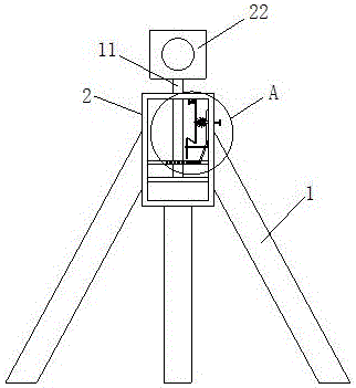
FIG. 1 is a schematic structural view of the integrated device of the present invention;
FIG. 2 is an enlarged schematic view of part A of the present invention;
FIG. 3 is an enlarged schematic view of part B of the present invention;
fig. 4 is a schematic view of the rectangular loop bar structure of the present invention.
In the figure: the measuring device comprises a support frame 1, a fixed frame 2, a rectangular loop bar 3, a first bevel gear 4, a second bevel gear 5, a first gear 6, a rectangular control rod 7, a first rack plate 8, a first connecting rod 9, a second rack plate 10, a rotating shaft 11, a second gear 12, a bearing 13, a first fixing rod 14, a second connecting rod 15, a limiting rod 16, a sliding chute 17, a first fixing plate 18, a second fixing rod 19, a spring 20, a second fixing plate 21 and a measuring level 22.
Detailed Description
The technical solutions in the embodiments of the present invention will be described clearly and completely with reference to the accompanying drawings in the embodiments of the present invention, and it is obvious that the described embodiments are only some embodiments of the present invention, not all embodiments. Based on the embodiments in the present invention, all other embodiments obtained by a person skilled in the art without creative work belong to the protection scope of the present invention.
Referring to fig. 1-4, the present invention provides a technical solution: a building surveying and mapping device for building construction comprises a supporting frame 1, wherein the top of the supporting frame 1 is hinged with a fixed frame 2, the inner wall of the fixed frame 2 is rotatably connected with a rectangular loop bar 3, the left side of the rectangular loop bar 3 is fixedly connected with a first bevel gear 4, the inner wall of the fixed frame 2 is rotatably connected with a first gear 6, the central position of the first gear 6 is fixedly connected with a second bevel gear 5, the first bevel gear 4 is meshed with the second bevel gear 5, the inner wall of the fixed frame 2 is slidably connected with a first rack plate 8, the right side of the first gear 6 is meshed with the first rack plate 8, the bottom of the first rack plate 8 is hinged with one end of a first connecting rod 9, the inner wall of the fixed frame 2 is provided with a chute 17, the chute 17 is slidably connected with a second rack plate 10, the right side of the second rack plate 10 is hinged with the other end of the first connecting rod 9, the inner part of the fixed frame 2 is rotatably connected with a rotating shaft 11, a second gear 12 is fixedly connected to the rotating shaft 11, the back of the second gear 12 is engaged with a second rack plate 10, a rectangular control rod 7 is arranged inside the rectangular loop bar 3, the rectangular control rod 7 is rectangular, so that the rectangular control rod 7 can drive the rectangular loop bar 3 to rotate, a bearing 13 is fixedly connected to the left side of the rectangular control rod 7, a first fixing rod 14 is fixedly connected to the bottom of the bearing 13, the bottom of the first fixing rod 14 is hinged to one end of a second connecting rod 15, the other end of the second connecting rod 15 is hinged to a limiting rod 16, a first fixing plate 18 is fixedly connected to the inner wall of the fixing frame 2, the limiting rod 16 penetrates through the first fixing plate 18, the limiting rod 16 is movably connected to the first fixing plate 18, so that the limiting rod 16 can only move up and down to play a limiting role, a second fixing plate 21 is fixedly connected to the inner wall of the fixing frame 2, and a spring 20 is fixedly connected to the left side of the second fixing plate 21, the construction surveying and mapping device for building construction is characterized in that a second fixing rod 19 is fixedly connected to the right side of a spring 20, the bottom of the second fixing rod 19 is fixedly connected with the top of a bearing 13, the spring 20 is arranged inside a fixing frame 2, when the rectangular control rod 7 is not controlled, the spring 20 can automatically push the rectangular control rod 7 to move towards the right side, so that a limiting rod 16 can automatically limit a second gear 12, the construction surveying and mapping device for building construction is more convenient to use, a rotating shaft 11 penetrates through the fixing frame 2, a measuring level gauge 22 is fixedly connected to the top of the rotating shaft 11, the rectangular control rod 7 penetrates through a rectangular loop bar 3, the rectangular control rod 7 is in sliding connection with the rectangular loop bar 3, the rectangular control rod 7 penetrates through a first bevel gear 4, the rectangular control rod 7 is movably connected with the first bevel gear 4, the construction surveying and mapping device for building construction is characterized in that the fixing frame 2 is provided with the rectangular loop bar 3, be provided with rectangle control lever 7 in the inside of rectangle loop bar 3 for rectangle control lever 7 can drive and measure the surveyor's level 22 and rotate, can also adjust rectangle control lever 7, makes gag lever post 16 can carry on spacingly to measuring surveyor's level 22 turned angle, has solved present building construction and has used building mapping device, when carrying out the angle modulation to mapping device, can't fix the angle of regulation, may influence the problem of mapping data accuracy.
When the measuring level 22 is in use (or in use), when the surveying and mapping angle of the measuring level 22 needs to be adjusted, the rectangular control rod 7 is pushed to the left, the rectangular control rod 7 moves to the left and drives the bearing 13 to move to the left, the bearing 13 moves to the left and drives the first fixing rod 14 to move to the left, the bottom of the second connecting rod 15 moves to the left by the movement of the first fixing rod 14, the second connecting rod 15 can rotate in an arc shape under the action of the movement of the bottom of the second connecting rod 15 to the left, so that the limiting rod 16 can be pushed to move to the upper side, the limiting rod 16 can not limit the second gear 12 by moving upwards through the limiting rod 16, then the rectangular control rod 7 is rotated, the rectangular control rod 7 rotates and drives the rectangular sleeve rod 3 to rotate, the rectangular sleeve rod 3 rotates and drives the first bevel gear 4 to rotate, the first bevel gear 4 rotates and drives the second bevel gear 5 to rotate, the second bevel gear 5 rotates and drives the first gear 6 to rotate, the first rack plate 8 is driven to move up and down through the rotation of the first gear 6, the first rack plate 8 moves up and down and drives the first connecting rod 9 to move downwards, the first connecting rod 9 moves downwards and drives the second rack plate 10 to move towards the left, the second gear 12 can rotate through the left movement of the first rack plate 10, the second gear 12 rotates and drives the rotating shaft 11 to rotate, the surveying and mapping angle of the measuring level 22 can be adjusted under the rotation action of the rotating shaft 11, the rectangular control rod 7 is loosened, the rectangular control rod 7 is automatically pushed to move towards the right under the action of the spring 20, the limiting rod 16 moves downwards through the right movement of the rectangular control rod 7, and the limiting rod 16 can automatically limit the second gear 12, the use is convenient for users.
Although embodiments of the present invention have been shown and described, it will be appreciated by those skilled in the art that changes, modifications, substitutions and alterations can be made in these embodiments without departing from the principles and spirit of the invention, the scope of which is defined in the appended claims and their equivalents.