Modular drying rack is used in production of fabrics coating
Technical Field
The utility model relates to a fabrics coating processing technology field specifically is a modular fabrics drying rack for paint produce.
Background
The weaving principle is a general name taken from spinning and weaving, but with the continuous development and perfection of a weaving knowledge system and a subject system, particularly after non-woven textile materials, three-dimensional compound weaving and other technologies are produced, the modern weaving refers to a multi-scale structure processing technology of fibers or fiber aggregates for clothing, industry and decoration, wherein the textile is not only produced by traditional hand spinning and weaving, but also produced by non-woven fabric technology, modern three-dimensional weaving technology, modern electrostatic nano-web technology and the like.
As early as in the original society, ancient people have understood to use local materials in order to adapt to climate change, use natural resources as raw materials for textile and printing and dyeing, and the hand textile tools which are simple to manufacture, the clothes, the air bags and the curtain carpets in daily life are products of textile and printing and dyeing technology, the textile is a product which is formed by processing and weaving textile fibers and is divided into two categories of woven fabric and knitted fabric, the correct stacking method of the textile is to select the textile which is favorable for ventilation and fire prevention, the all-cotton cloth is preferably placed in a place with good ventilation, and the textile is usually dyed in order to improve the ornamental value of the textile, generally can hang the fabrics and air-dry on the sunning frame after dyeing is accomplished, current sunning frame can not be according to the length adjustment height of fabrics, the removal of not being convenient for, poor stability when placing can not assist the air-dry to the fabrics.
SUMMERY OF THE UTILITY MODEL
An object of the utility model is to provide a modular drying rack for textile coating production possesses adjustable sunning height, is convenient for remove, places stable and supplementary air-dried advantage, has solved current drying rack and can not be according to the length adjustment height of fabrics, and the removal of being not convenient for is poor in stability when placing, can not assist air-dried problem to the fabrics.
In order to achieve the above object, the utility model provides a following technical scheme: a combined drying rack for textile coating production comprises a bottom plate, wherein four corners of the bottom plate are provided with fixing mechanisms, the inner cavity of the fixed mechanism is provided with a moving mechanism, the two sides of the top of the bottom plate are provided with sliding mechanisms, the tops of the two sliding mechanisms are fixedly connected with connecting plates, one side opposite to the two connecting plates is fixedly connected with a blowing mechanism, the center of the top of the bottom plate is provided with a lifting mechanism which comprises a threaded column rotationally connected with the bottom plate through a bearing, the surface of the threaded column is in threaded connection with a threaded sleeve, the top end of the threaded column is fixedly connected with a first handle, both sides of the threaded sleeve are fixedly connected with mounting plates, the top of each mounting plate is provided with a fastening mechanism, a plurality of mounting holes are formed in the front side of the mounting plate from left to right, and an inner cavity of each mounting hole is provided with an airing rod in a penetrating mode.
Preferably, the fixing mechanism comprises a threaded long rod fixedly connected with the bottom plate, and a threaded cap is connected to the surface of the threaded long rod in a threaded manner.
Preferably, the moving mechanism comprises a roller carrier fixedly connected with the threaded long rod, and an inner cavity of the roller carrier is rotatably connected with a roller through a rotating shaft.
Preferably, slide mechanism includes the slide bar with bottom plate fixed connection, the top and the connecting plate fixed connection of slide bar, the surperficial sliding connection of slide bar has the sliding sleeve, one side and the mounting panel fixed connection of sliding sleeve.
Preferably, the blowing mechanism comprises a first installation box fixedly connected with the connecting plate, an air heater is arranged in an inner cavity of the first installation box, a left air outlet and a right air outlet of the air heater are both communicated with a first air guide pipe, and two sides of the bottom of the first air guide pipe are both communicated with an air outlet cover.
Preferably, the two sides of the bottom of the first mounting box are respectively provided with a second air guide pipe in a penetrating manner, the bottom of the inner cavity of the second air guide pipe is provided with an air guide sheet, the top end of the second air guide pipe extends to the inner cavity of the first mounting box and is fixedly connected with the first air guide pipe, and the air outlet cover is located in the inner cavity of the second air guide pipe.
Preferably, the two sides of the air heater are fixedly connected with fixing rods, and one end, far away from the air heater, of each fixing rod is fixedly connected with the installation box.
Preferably, fastening device includes the install bin two with install panel fixed connection, the top of install bin two is run through and is provided with the screw thread quarter butt, screw thread quarter butt surface and two threaded connection of install bin, the top fixedly connected with handle two of screw thread quarter butt, the bottom of handle two extends to the inner chamber of install bin two and is connected with the push pedal through the bearing rotation, a plurality of depression bars of fixedly connected with in proper order from a left side to the right side in the bottom of push pedal, the bottom of depression bar all runs through the top of install bin and extends to the inner chamber of mounting hole.
Compared with the prior art, the beneficial effects of the utility model are as follows:
1. the utility model discloses a moving mechanism's cooperation promotes this sunning frame to sunning place, fix this sunning frame through fixed establishment, improve the stability when placing, insert the inner chamber of mounting hole with the sunning pole, fix the sunning pole through fastening device, improve the stability of fabrics string on the sunning pole, when the fabrics is longer, drive the mounting panel through elevating system and adjust the height of sunning pole, this formula fabrics is sunning frame for paint produce possesses adjustable sunning height, be convenient for remove, place stable and supplementary air-dried advantage, the length adjustment height that current sunning frame can not be according to the fabrics has been solved, be not convenient for remove, poor stability when placing, can not assist air-dried problem to the fabrics.
2. The utility model fixes the drying rack through the fixing mechanism, improves the stability of the drying rack on the ground, facilitates the user to move the drying rack through the arrangement of the moving mechanism, improves the flexibility of the drying rack, limits the threaded sleeve through the arrangement of the sliding mechanism and the matching mounting plate, improves the stability of the threaded sleeve when the textile is moved up and down, starts the hot air blower to air-dry the textile in an auxiliary way when the textile is hung on the drying rack through the arrangement of the blowing mechanism, disperses the hot air blown out by the hot air blower through the wind guide sheet, and evenly dries the surface of the textile, thereby reducing the air drying time of the textile, further greatly improving the production efficiency, guides and diffuses the blown air through the matching use of the second wind guide pipe and the wind guide sheet, and greatly improving the auxiliary air drying effect of the drying rack, through the setting of dead lever, fix the air heater, improved the stability of air heater when placing, through fastening device's setting, fix the sunning pole, improved the stability that the fabrics hung on the sunning pole.
Drawings
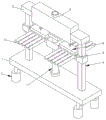
Fig. 1 is a perspective view of the present invention;
FIG. 2 is a front sectional view of the present invention;
fig. 3 is a partially enlarged view of a in fig. 2 according to the present invention.
In the figure: 1. a base plate; 2. a fixing mechanism; 3. a moving mechanism; 4. a sliding mechanism; 5. a connecting plate; 6. A blowing mechanism; 7. a lifting mechanism; 8. mounting a plate; 9. a fastening mechanism; 10. mounting holes; 11. an airing rod; 21. a threaded long rod; 22. a threaded cap; 31. a roller frame; 32. a roller; 41. a slide bar; 42. A sliding sleeve; 61. installing a first box; 62. a hot air blower; 63. a first air duct; 64. an air outlet cover; 65. a second air duct; 66. a wind guide sheet; 67. fixing the rod; 71. a threaded post; 72. a threaded sleeve; 73. a first handle; 91. a second installation box; 92. a threaded stub; 93. a second handle; 94. pushing the plate; 95. a pressure lever.
Detailed Description
The technical solutions in the embodiments of the present invention will be described clearly and completely with reference to the accompanying drawings in the embodiments of the present invention, and it is obvious that the described embodiments are only some embodiments of the present invention, not all embodiments. Based on the embodiments in the present invention, all other embodiments obtained by a person skilled in the art without creative work belong to the protection scope of the present invention.
Referring to fig. 1-3, the present invention provides a technical solution: a combined type drying rack for textile coating production comprises a bottom plate 1, wherein four corners of the bottom plate 1 are respectively provided with a fixing mechanism 2, the fixing mechanisms 2 comprise threaded long rods 21 fixedly connected with the bottom plate 1, the surfaces of the threaded long rods 21 are in threaded connection with threaded caps 22, the drying rack is fixed through the arrangement of the fixing mechanisms 2, the stability of the drying rack horizontally placed on the ground is improved, the inner cavity of each fixing mechanism 2 is provided with a moving mechanism 3, each moving mechanism 3 comprises a roller frame 31 fixedly connected with the threaded long rods 21, the inner cavity of each roller frame 31 is rotatably connected with a roller 32 through a rotating shaft, the drying rack is convenient to move by a user through the arrangement of the moving mechanisms 3, the flexibility of the drying rack is improved, two sides of the top of the bottom plate 1 are respectively provided with a sliding mechanism 4, each sliding mechanism 4 comprises a sliding rod 41 fixedly connected with the bottom plate 1, the top and the connecting plate 5 fixed connection of slide bar 41, the surperficial sliding connection of slide bar 41 has sliding sleeve 42, one side and the mounting panel 8 fixed connection of sliding sleeve 42, and it is spacing to cooperate mounting panel 8 to carry out threaded sleeve 72 through setting up of slide mechanism 4, has improved the stability of threaded sleeve 72 when reciprocating, the equal fixedly connected with connecting plate 5 in top of two slide mechanism 4.
In the utility model, the opposite side of the two connecting plates 5 is fixedly connected with the blowing mechanism 6, the blowing mechanism 6 comprises a first mounting box 61 fixedly connected with the connecting plates 5, the inner cavity of the first mounting box 61 is provided with an air heater 62, the left air outlet and the right air outlet of the air heater 62 are both communicated with a first air duct 63, both sides of the bottom of the first air duct 63 are both communicated with an air outlet cover 64, both sides of the bottom of the first mounting box 61 are both provided with a second air duct 65 in a penetrating way, the bottom of the inner cavity of the second air duct 65 is provided with an air guide sheet 66, the top end of the second air duct 65 extends to the inner cavity of the first mounting box 61 and is fixedly connected with the first air duct 63, the air outlet cover 64 is positioned in the inner cavity of the second air duct 65, the textiles are hung on the drying rack to be dried by the blowing mechanism 6, the air heater 62 is started to assist in air drying the textiles, the hot air blown out by the air guide sheet 66 is dispersed, carry out evenly weathering to the fabrics surface, thereby the air-dry time of fabrics has been reduced, and then production efficiency has been improved greatly, cooperation through second guide duct 65 and guide vane 66 is used, lead to and spread the wind that blows off, this sunning frame's supplementary air-dry effect has been improved greatly, the equal fixedly connected with dead lever 67 in both sides of air heater 62, one end and the install bin 61 fixed connection that air heater 62 was kept away from to dead lever 67, setting through dead lever 67, fix air heater 62, the stability of air heater 62 when placing has been improved.
The utility model discloses in, the center department at 1 top of bottom plate is provided with elevating system 7, and elevating system 7 includes and rotates the screw thread post 71 of being connected through bearing and bottom plate 1, and the surperficial threaded connection of screw thread post 71 has the thread bush 72, and the top fixedly connected with handle 73 of screw thread post 71, the equal fixedly connected with mounting panel 8 in both sides of thread bush 72, a plurality of mounting hole 10 has been seted up to the right side from a left side to the front side of mounting panel 8, and the inner chamber of mounting hole 10 runs through and is provided with sunning pole 11.
The utility model discloses in, the top of mounting panel 8 is provided with fastening device 9, fastening device 9 includes two 91 of install bin with 8 fixed connection of mounting panel, the top of install bin two 91 is run through and is provided with screw short rod 92, screw short rod 92 surface and two 91 threaded connection of install bin, the top fixedly connected with handle two 93 of screw short rod 92, the bottom of handle two 93 extends to the inner chamber of install bin two 91 and is connected with push pedal 94 through the bearing rotation, a plurality of depression bars 95 of fixedly connected with are in proper order from a left side to the right side in push pedal 94's bottom, the bottom of depression bar 95 all runs through the top of mounting panel 8 and extends to the inner chamber of mounting hole 10, setting through fastening device 9, fix airing pole 11, the stability of fabrics string on airing pole 11 has been improved.
The working principle is as follows: when the utility model is used, the user pushes the drying rack to move to the drying place through the matching use of the roller rack 31 and the roller 32, the screw cap 22 is rotated, the screw cap 22 is matched with the screw thread on the surface of the long screw rod 21 to move downwards, and the roller 32 is covered until the screw cap 22 supports the bottom plate 1, thereby improving the stability of the drying device when being placed, the drying rod 11 is inserted into the inner cavity of the mounting hole 10, the handle two 93 is rotated, the handle two 93 drives the short screw rod 92 to rotate, the short screw rod 92 moves downwards through the screw thread matching mounting box two 91 on the surface, the short screw rod 92 pushes the push plate 94 to move downwards while moving downwards, the push plate 94 drives the compression bar 95 to press the drying rod 11 in the inner cavity of the mounting hole 10, thereby improving the stability of the textile hanging on the drying rod 11, when the textile body is longer, the user can rotate the first handle 73, the first handle 73 drives the threaded sleeve 72 to rotate, the threaded sleeve 72 drives the threaded column 71 to move up and down through threads on the surface, and the threaded column 71 drives the airing rod 11 to move up and down through the mounting plate 8, so that the purpose of freely adjusting the airing height is achieved, and finally the purposes of adjusting the airing height, facilitating movement, placing stability and assisting air drying are achieved.
In summary, the following steps: this combination formula is sunning frame for textile coating production, cooperation through moving mechanism 3 promotes this sunning frame to sunning place, fix this sunning frame through fixed establishment 2, stability when placing is improved, insert the inner chamber of mounting hole 10 with sunning pole 11, fix sunning pole 11 through fastening device 9, improve the stability of fabrics string on sunning pole 11, when the fabrics is longer, drive mounting panel 8 through elevating system 7 and adjust the height of sunning pole 11, this combination formula is sunning frame for textile coating production possesses adjustable sunning height, be convenient for remove, place stable and supplementary air-dried advantage, the length adjustment height that current sunning frame can not be according to the fabrics has been solved, be not convenient for remove, poor stability when placing, can not assist air-dried problem to the fabrics.
It is noted that, herein, relational terms such as first and second, and the like may be used solely to distinguish one entity or action from another entity or action without necessarily requiring or implying any actual such relationship or order between such entities or actions. Also, the terms "comprises," "comprising," or any other variation thereof, are intended to cover a non-exclusive inclusion, such that a process, method, article, or apparatus that comprises a list of elements does not include only those elements but may include other elements not expressly listed or inherent to such process, method, article, or apparatus.
The electrical components presented in the document are all electrically connected with an external master controller and 220V mains, and the master controller can be a conventional known device controlled by a computer or the like.
Although embodiments of the present invention have been shown and described, it will be appreciated by those skilled in the art that changes, modifications, substitutions and alterations can be made in these embodiments without departing from the principles and spirit of the invention, the scope of which is defined in the appended claims and their equivalents.