CN214290339U - Stainless steel strip-shaped hole punching die - Google Patents
Stainless steel strip-shaped hole punching die Download PDFInfo
- Publication number
- CN214290339U CN214290339U CN202022696290.1U CN202022696290U CN214290339U CN 214290339 U CN214290339 U CN 214290339U CN 202022696290 U CN202022696290 U CN 202022696290U CN 214290339 U CN214290339 U CN 214290339U
- Authority
- CN
- China
- Prior art keywords
- die
- shaped hole
- punch
- plate
- strip
- Prior art date
- Legal status (The legal status is an assumption and is not a legal conclusion. Google has not performed a legal analysis and makes no representation as to the accuracy of the status listed.)
- Active
Links
- 238000004080 punching Methods 0.000 title claims abstract description 21
- 229910001220 stainless steel Inorganic materials 0.000 title claims abstract description 13
- 239000010935 stainless steel Substances 0.000 title claims abstract description 13
- 239000002184 metal Substances 0.000 claims abstract description 4
- 230000002035 prolonged effect Effects 0.000 abstract description 5
- 238000004519 manufacturing process Methods 0.000 abstract description 4
- 239000002994 raw material Substances 0.000 abstract description 2
- 238000000034 method Methods 0.000 description 3
- 239000003208 petroleum Substances 0.000 description 3
- 230000009286 beneficial effect Effects 0.000 description 1
- 230000007547 defect Effects 0.000 description 1
- 238000010586 diagram Methods 0.000 description 1
- 239000000463 material Substances 0.000 description 1
- 238000003825 pressing Methods 0.000 description 1
Images

Landscapes
- Punching Or Piercing (AREA)
- Perforating, Stamping-Out Or Severing By Means Other Than Cutting (AREA)
Abstract
The utility model discloses a stainless steel bar-shaped hole punching die, wherein a punching die main body comprises a die lower part and a die upper part, a longitudinal guide structure is arranged between the die lower part and the die upper part, a bar-shaped hole punch is fixedly assembled on the bottom surface of the die upper part, and a slot is formed in the die lower part corresponding to the bar-shaped hole punch; the head part of the strip-shaped hole punch is provided with a titanium-plated metal film; the scheme improves the prior strip-shaped hole punch, the fixing part of the clamping plate adopts the taper for the first time, the downward pulling force is offset by the taper of the fixing part of the punch, and the breaking probability of the hanging table is reduced; the punch part is subjected to titanizing treatment, so that the service life of the punch is prolonged; the improved punch has the advantages that the service life is greatly prolonged, the economic value is higher, a large amount of raw materials are saved due to the design of the taper in the manufacturing process, the manufacturing cost is reduced, and the improved punch has the characteristics of convenience in processing, smooth appearance, long service life, high repeated use frequency and the like.
Description
Technical Field
The utility model relates to a cut-out press technical field of petroleum pipeline oversheath specifically is a stainless steel bar hole cut-out press.
Background
In the processing process of the outer sheath of the petroleum pipeline, the outer sheath needs to be punched, a punching die in the prior art has certain defects, the phenomenon that materials are wasted in the design of a punch of the existing punching die is serious, the processing cost is improved, meanwhile, the punch is short in service life, the repeated use frequency is low, and the die is frequently repaired.
SUMMERY OF THE UTILITY MODEL
An object of the utility model is to provide a stainless steel bar shape hole-punching die to solve the problem that proposes among the above-mentioned background art.
In order to achieve the above object, the utility model provides a following technical scheme: a stainless steel strip-shaped hole punching die comprises a punching die main body, wherein the punching die main body comprises a die lower part and a die upper part, a longitudinal guide structure is arranged between the die lower part and the die upper part, a strip-shaped hole punch is fixedly assembled on the bottom surface of the die upper part, and a slot is formed in the die lower part corresponding to the strip-shaped hole punch;
the fixed part of the clamping plate of the strip-shaped hole punch is provided with taper, and the head of the strip-shaped hole punch is provided with a titanium-plated metal film.
Preferably, the lower part of the die comprises a lower supporting plate, a base plate is uniformly and fixedly assembled on the upper surface of the lower supporting plate, a lower die holder is fixedly assembled at the upper end of the base plate, a lower base plate and a lower die plate are arranged on the middle part of the upper surface of the lower die holder from bottom to top, a cylindrical pin is fixedly connected among the lower base plate, the lower die plate and the lower die holder, and slots are formed in the middle parts of the lower base plate and the lower die plate.
Preferably, mould upper portion includes the upper die base, the upper die base bottom surface is from last to being equipped with upper padding plate and punch holder down, fixedly connected with cylindric lock between upper padding plate, punch holder and the upper die base, the fixed joint of bar hole drift is in upper padding plate bottom surface middle part, and bar hole drift runs through the upper padding plate.
Preferably, the longitudinal guide structure comprises sliding outer guide pillars arranged between the left side and the right side of the upper die base and the lower die base, and inner guide pillars are arranged between the left side and the right side of the upper backing plate and the lower die plate.
Preferably, the outer side of the strip-shaped hole punch is sleeved with a stop plate and an upper stripping plate from top to bottom, an inner hexagonal screw is fixedly connected between the stop plate and the upper stripping plate, and an inner guide pillar penetrates through the stop plate and the upper stripping plate.
Compared with the prior art, this scheme has designed a stainless steel bar shape hole cut-out press, has following beneficial effect:
(1) the scheme improves the prior strip-shaped hole punch, the fixing part of the clamping plate adopts the taper for the first time, the downward pulling force is offset by the taper of the fixing part of the punch, and the breaking probability of the hanging table is reduced; and the punch part is subjected to titanizing treatment, so that the service life of the punch is prolonged.
(2) The improved punch has the advantages that the service life is greatly prolonged, the economic value is higher, a large amount of raw materials are saved due to the design of the taper in the manufacturing process, the manufacturing cost is reduced, and the improved punch has the characteristics of convenience in processing, smooth appearance, long service life, high repeated use frequency and the like.
Drawings
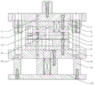
FIG. 1 is a schematic structural view of the present invention;
fig. 2 is the structural schematic diagram of the middle strip-shaped hole punch of the present invention.
In the figure: 1 upper die base, 2 upper backing plates, 3 upper clamping plates, 4 stop plates, 5 upper stripper plates, 6 lower die plates, 7 lower backing plates, 8 lower die bases, 9 backing plates, 10 lower support plates, 11 cylindrical pins, 12 inner guide pillars, 13 inner hexagonal screws, 14 strip-shaped hole punches and 15 sliding outer guide pillars.
Detailed Description
The technical solutions in the embodiments of the present invention will be described clearly and completely with reference to the accompanying drawings in the embodiments of the present invention, and it is obvious that the described embodiments are only some embodiments of the present invention, not all embodiments. Based on the embodiments in the present invention, all other embodiments obtained by a person skilled in the art without creative work belong to the protection scope of the present invention.
Referring to fig. 1 and fig. 2, the present invention provides a technical solution: a stainless steel strip-shaped hole punching die comprises a punching die main body, wherein the punching die main body comprises a die lower part and a die upper part, a longitudinal guide structure is arranged between the die lower part and the die upper part, a strip-shaped hole punch 14 is fixedly assembled on the bottom surface of the die upper part, and a slot is formed in the die lower part corresponding to the strip-shaped hole punch 14;
the clamping plate fixing part of the strip-shaped hole punch 14 is provided with taper, and the head part of the strip-shaped hole punch 14 is provided with a titanium-plated metal film; the dimension ratio of the strip-shaped punch 14 in this embodiment is shown in fig. 2, for example.
The existing strip-shaped hole punch 14 is improved, the taper is adopted for the first time at the clamping plate fixing part, the downward pulling force is offset by the taper of the punch fixing part, and the breaking probability of a hanging table is reduced; and the punch part is subjected to titanizing treatment, so that the service life of the punch is prolonged.
The mould lower part includes bottom plate 10, and the even fixed backing plate 9 that is equipped with of upper surface of bottom plate 10, the upper end fixed mounting of backing plate 9 has die holder 8, and supreme 7 and the lower bolster 6 of being equipped with are down followed to 8 upper surface middle parts of die holder, fixedly connected with cylindric lock 11 between 7, the lower bolster 6 of bottom bolster and the lower bolster 8, and the slot has been seted up at 7 and 6 middle parts of lower bolster of bottom bolster.
Mould upper portion includes upper die base 1, and 1 bottom surface of upper die base is from last to being equipped with upper padding plate 2 and punch holder 3 down, fixedly connected with cylindric lock 11 between upper padding plate 2, punch holder 3 and the upper die base 1, and the fixed joint of bar hole drift 14 is in 2 bottom surfaces middle parts of upper padding plate, and bar hole drift 14 runs through upper padding plate 2.
The longitudinal guide structure comprises a sliding outer guide post 15 arranged between the left side and the right side of the upper die holder 1 and the lower die holder 8, and an inner guide post 12 arranged between the left side and the right side of the upper backing plate 2 and the lower die plate 6.
Through the connection of the sliding outer guide post 15 and the sliding inner guide post 12, the upper part of the die is connected with the lower part of the die, the upper part of the die drives the strip-shaped hole punch 14 to move downwards in the pressing process, and the petroleum pipeline outer sheath placed on the lower template 6 is punched.
The outer side of the strip-shaped hole punch 14 is sleeved with a stop plate 4 and an upper stripper plate 5 from top to bottom, an inner hexagonal screw 13 is fixedly connected between the stop plate 4 and the upper stripper plate 5, and an inner guide post 12 penetrates through the stop plate 4 and the upper stripper plate 5; the outer sheath to be punched is clamped by the stop plate 4 and the upper stripping plate 5, and the upper part of the die plays a role in demoulding after punching in the lifting process.
It is obvious to a person skilled in the art that the invention is not restricted to details of the above-described exemplary embodiments, but that it can be implemented in other specific forms without departing from the spirit or essential characteristics of the invention. The present embodiments are therefore to be considered in all respects as illustrative and not restrictive, the scope of the invention being indicated by the appended claims rather than by the foregoing description, and all changes which come within the meaning and range of equivalency of the claims are therefore intended to be embraced therein. Any reference sign in a claim should not be construed as limiting the claim concerned.
Furthermore, it should be understood that although the present description refers to embodiments, not every embodiment may contain only a single embodiment, and such description is for clarity only, and those skilled in the art should integrate the description, and the embodiments may be combined as appropriate to form other embodiments understood by those skilled in the art.
Claims (5)
1. The utility model provides a stainless steel strip shape hole cut-out press which characterized in that: the punching die comprises a punching die main body, wherein the punching die main body comprises a die lower part and a die upper part, a longitudinal guide structure is arranged between the die lower part and the die upper part, a strip-shaped hole punch (14) is fixedly assembled on the bottom surface of the die upper part, and a slot is formed in the die lower part corresponding to the strip-shaped hole punch (14);
the fixed part of the clamping plate of the strip-shaped hole punch (14) is provided with taper, and the head of the strip-shaped hole punch (14) is provided with a titanium-plated metal film.
2. The stainless steel strip-shaped hole-punching die as set forth in claim 1, wherein: the mould lower part includes bottom plate (10), the even fixed backing plate (9) that is equipped with of upper surface of bottom plate (10), the upper end fixed mounting of backing plate (9) has die holder (8), supreme lower bolster (7) and lower bolster (6) are equipped with down from lower in die holder (8) upper surface middle part, fixedly connected with cylindric lock (11) between lower bolster (7), lower bolster (6) and die holder (8), the slot has been seted up at lower bolster (7) and lower bolster (6) middle part.
3. A stainless steel strip-shaped hole-punching die as set forth in claim 2, wherein: mould upper portion includes upper die base (1), upper die base (1) bottom surface is from last to being equipped with upper padding plate (2) and punch holder (3) down, fixedly connected with cylindric lock (11) between upper padding plate (2), punch holder (3) and upper die base (1), fixed joint in upper padding plate (2) bottom surface middle part of bar hole drift (14), and bar hole drift (14) run through upper padding plate (2).
4. A stainless steel strip-shaped hole-punching die as set forth in claim 3, wherein: the longitudinal guide structure comprises a sliding outer guide post (15) arranged between the left side and the right side of the upper die base (1) and the lower die base (8), and an inner guide post (12) is arranged between the left side and the right side of the upper backing plate (2) and the lower die plate (6).
5. The stainless steel strip-shaped hole-punching die as set forth in claim 4, wherein: the outer side of the strip-shaped hole punch (14) is sleeved with a stop plate (4) and an upper stripping plate (5) from top to bottom, the stop plate (4) and the upper stripping plate (5) are fixedly connected with hexagon socket head cap screws (13), and the inner guide columns (12) penetrate through the stop plate (4) and the upper stripping plate (5).
Priority Applications (1)
| Application Number | Priority Date | Filing Date | Title |
|---|---|---|---|
| CN202022696290.1U CN214290339U (en) | 2020-11-20 | 2020-11-20 | Stainless steel strip-shaped hole punching die |
Applications Claiming Priority (1)
| Application Number | Priority Date | Filing Date | Title |
|---|---|---|---|
| CN202022696290.1U CN214290339U (en) | 2020-11-20 | 2020-11-20 | Stainless steel strip-shaped hole punching die |
Publications (1)
| Publication Number | Publication Date |
|---|---|
| CN214290339U true CN214290339U (en) | 2021-09-28 |
Family
ID=77844664
Family Applications (1)
| Application Number | Title | Priority Date | Filing Date |
|---|---|---|---|
| CN202022696290.1U Active CN214290339U (en) | 2020-11-20 | 2020-11-20 | Stainless steel strip-shaped hole punching die |
Country Status (1)
| Country | Link |
|---|---|
| CN (1) | CN214290339U (en) |
-
2020
- 2020-11-20 CN CN202022696290.1U patent/CN214290339U/en active Active
Similar Documents
| Publication | Publication Date | Title |
|---|---|---|
| CN204523999U (en) | The diel of underslung bearing flap | |
| CN205270577U (en) | Deep -drawing compound die that punches a hole | |
| CN215918842U (en) | Stamping die is used in accessories processing | |
| CN208288766U (en) | A kind of sectional aluminum extruded material punching die | |
| CN211803377U (en) | A mould for producing cavity glass aluminum strip connecting piece | |
| CN211727191U (en) | Stamping die | |
| CN211638311U (en) | Hard alloy die for pressing multiple numerical control blade products | |
| CN216126420U (en) | Double-layer fastened stamping die | |
| CN209531885U (en) | A punch bending die | |
| CN207606151U (en) | A kind of diel | |
| CN222873171U (en) | Material-saving stamping progressive die | |
| CN206643196U (en) | A kind of diel of band die sinking power-assisted | |
| CN215941222U (en) | Stamping die of finished product no-joint cutter trace | |
| CN222058622U (en) | A punch assembly for a stretch stamping die | |
| CN204584003U (en) | Cylindrical member side opening punch die | |
| CN221620531U (en) | Unilateral structure of preventing side force that punches a hole | |
| CN222725230U (en) | A metal stamping and drawing die | |
| CN222695740U (en) | Hard alloy stamping die | |
| CN217550900U (en) | Punching die for machining shear blade | |
| CN216705673U (en) | Mould capable of being used for multiple material belts | |
| CN219819981U (en) | Fine hole precision punching jig | |
| CN217141933U (en) | Multi-punch die for punch press | |
| CN221474917U (en) | Punch clamp | |
| CN216780049U (en) | Precision stamping die with buffer structure | |
| CN214290453U (en) | Movable punch structure |
Legal Events
| Date | Code | Title | Description |
|---|---|---|---|
| GR01 | Patent grant | ||
| GR01 | Patent grant |