CN214275627U - Lamp slot mounting structure - Google Patents
Lamp slot mounting structure Download PDFInfo
- Publication number
- CN214275627U CN214275627U CN202120411736.3U CN202120411736U CN214275627U CN 214275627 U CN214275627 U CN 214275627U CN 202120411736 U CN202120411736 U CN 202120411736U CN 214275627 U CN214275627 U CN 214275627U
- Authority
- CN
- China
- Prior art keywords
- plate
- honeycomb
- light trough
- vertical connecting
- limiting plate
- Prior art date
- Legal status (The legal status is an assumption and is not a legal conclusion. Google has not performed a legal analysis and makes no representation as to the accuracy of the status listed.)
- Withdrawn - After Issue
Links
- 238000009434 installation Methods 0.000 claims abstract description 32
- 238000003780 insertion Methods 0.000 claims abstract description 18
- 230000037431 insertion Effects 0.000 claims abstract description 16
- 239000000463 material Substances 0.000 claims description 10
- 230000000694 effects Effects 0.000 abstract description 6
- 238000005034 decoration Methods 0.000 description 12
- XAGFODPZIPBFFR-UHFFFAOYSA-N aluminium Chemical compound [Al] XAGFODPZIPBFFR-UHFFFAOYSA-N 0.000 description 7
- 229910052782 aluminium Inorganic materials 0.000 description 7
- 230000001413 cellular effect Effects 0.000 description 7
- 238000000034 method Methods 0.000 description 7
- 230000009471 action Effects 0.000 description 3
- 230000008569 process Effects 0.000 description 3
- 239000002344 surface layer Substances 0.000 description 3
- 230000008859 change Effects 0.000 description 2
- 238000000465 moulding Methods 0.000 description 2
- 229910000831 Steel Inorganic materials 0.000 description 1
- 238000010521 absorption reaction Methods 0.000 description 1
- 230000001154 acute effect Effects 0.000 description 1
- 238000005452 bending Methods 0.000 description 1
- 239000012792 core layer Substances 0.000 description 1
- 230000006378 damage Effects 0.000 description 1
- 230000001066 destructive effect Effects 0.000 description 1
- 239000000839 emulsion Substances 0.000 description 1
- 238000005516 engineering process Methods 0.000 description 1
- 238000009413 insulation Methods 0.000 description 1
- 239000010410 layer Substances 0.000 description 1
- 230000013011 mating Effects 0.000 description 1
- 238000012986 modification Methods 0.000 description 1
- 230000004048 modification Effects 0.000 description 1
- 239000003973 paint Substances 0.000 description 1
- 238000004321 preservation Methods 0.000 description 1
- 230000001105 regulatory effect Effects 0.000 description 1
- 230000035939 shock Effects 0.000 description 1
- 239000010959 steel Substances 0.000 description 1
- 238000006467 substitution reaction Methods 0.000 description 1
- 239000002023 wood Substances 0.000 description 1
Images


Landscapes
- Connection Of Plates (AREA)
Abstract
The utility model discloses a light trough mounting structure relates to assembled fitment technical field. The honeycomb panel comprises a light trough line and fixed profiles fixed at the edge parts of the honeycomb panel, wherein sliding insertion strips are arranged on the light trough line side by side, a plurality of sliding insertion grooves are correspondingly arranged on the fixed profiles, and the light trough line is in sliding connection with the fixed profiles; the honeycomb plate fixing device also comprises a matching fixing piece which is fixedly arranged at the edge part of the honeycomb plate and is connected with the fixing section in a clamping manner, clamping teeth arranged on the matching fixing piece and clamping grooves correspondingly arranged on the fixing section; the matching fixing piece is fixed with the honeycomb plate in a nailing mode, and the matching fixing piece is further arranged in an enclosing space formed when the fixing section is installed at the edge of the honeycomb plate. The utility model discloses can adjust in a flexible way in order to adapt to different fluorescent tube installations, improve light trough mounting structure, guarantee its installation quality, adapt to the honeycomb panel structure, the effect is showing.
Description
Technical Field
The utility model relates to an assembled fitment technical field especially relates to a light trough mounting structure.
Background
The aluminum honeycomb plate is suitable for civil buildings, vehicle and ship decorations and the like. Since the honeycomb material has excellent performances of high wind pressure resistance, shock absorption, sound insulation, heat preservation, flame retardance, high specific strength and the like, the honeycomb material is used in various civil fields in sixty years abroad, and the development is fast, so that the honeycomb technology is applied to various fields of civil industry in recent years in China. The aluminum honeycomb panel curtain wall has the advantages of light weight, high strength, high rigidity and the like, and is widely applied to the decoration of the outer wall of a high-rise building, the mutually connected aluminum honeycomb cores are like a plurality of I-shaped steel, and the core layers are distributed and fixed in the whole panel surface, so that the panel is more stable, the wind pressure resistance performance of the aluminum honeycomb panel curtain wall is greatly superior to that of an aluminum plastic plate and an aluminum single plate, and the aluminum honeycomb panel curtain wall has the characteristics of difficult deformation and good flatness; even if the cellular size of the cellular board is very large, the cellular board can achieve extremely high flatness, and is the preferred light material in the building industry.
As a ring in the assembled drop ceiling system, the light trough installation plays a role in drawing dragon points and eyes on the ceiling structure, so that the assembled ceiling has a high-quality decoration installation effect. When the light trough lines are installed in the suspended ceiling structure mainly composed of the cellular boards, the structural modeling characteristics of the cellular boards are also considered, the light trough lines can be stably fixed at the edge parts of the cellular boards, and meanwhile, the deformation of the cellular boards caused by the installation of the light trough lines is avoided, so that the suspended ceiling installation is influenced. The need for their dark-line mounting to eliminate mounting marks is also considered.
The utility model discloses a utility model patent of a light trough molding structure that patent number CN201721923671.0 discloses, from top to bottom include first decoration panel, bend board and second decoration panel in proper order, first decoration panel with the second decoration panel sets up in parallel, the first end of bend board is fixed in the front of first decoration panel, the second end of bend board is fixed in the back of second decoration panel; the lamp groove modeling structure further comprises lamp groove lines, the lamp groove lines are arranged at the first end of the second decoration panel and used for forming a lamp groove used for installing a lamp together with the bending plate and the second decoration panel, and the second end of the second decoration panel is used for being fixed with a wall. The utility model discloses a light trough molding structure does not need the leveling, need not to use the davit to fix the light trough, need not to use the emulsion paint, can integral hoisting, realizes the modularization installation, and simple to operate saves manual work and time, and the installation effectiveness is high.
In this patent, adopt the fixed mode of nailing to fix the lantern trough lines at the limit portion of decorative board, and for traditional wood veneer, it is still reasonable, but for the honeycomb panel, weak surface course can lead to the nailing fixed effect variation or even inefficacy, still can destroy the honeycomb panel when serious. The light trough lines are installed more rigidly, have obvious installation traces, and do not meet the high standard requirements in the field of high-end assembly type installation.
SUMMERY OF THE UTILITY MODEL
The utility model provides a light trough mounting structure, light trough lines remove adjustably to adapt to different fluorescent tube installations, still strengthen honeycomb panel edge intensity when installing honeycomb panel limit portion, high standard realizes installing the traceless mounting means, when guaranteeing that the light trough installs higher installation effect, has still promoted the installation aesthetic property, is used for solving above-mentioned technical problem.
The utility model provides a technical scheme of above-mentioned problem is: the lamp groove installation structure comprises lamp groove lines and a fixed section bar which is connected with the lamp groove lines and fixed at the edge of a honeycomb panel, wherein sliding insertion strips are arranged on the lamp groove lines side by side, a plurality of sliding insertion grooves are correspondingly arranged on the fixed section bar, and the lamp groove lines are connected with the fixed section bar in a sliding manner; the honeycomb plate fixing device further comprises a matching fixing piece which is fixedly arranged at the edge part of the honeycomb plate and is connected with the fixing section in a clamping mode, clamping teeth arranged on the matching fixing piece and clamping grooves correspondingly arranged on the fixing section; the cooperation mounting is fixed with the honeycomb panel nail dress, and the cooperation mounting is still arranged in the enclosure space that forms when fixed sectional material installs in honeycomb panel limit portion department, the cooperation mounting still links to each other with the fixed sectional material joint.
Furthermore, the light trough line comprises a first vertical connecting plate, a first upper limiting plate and a first lower limiting plate which are respectively arranged at two ends of the first vertical connecting plate and face to the same side of the first vertical connecting plate; the first lower limiting plate is integrally provided with a sliding insertion strip. The light trough lines form a light trough installation space through the first vertical connecting plate and the first upper limiting plate which are matched with the adjusting plate, and the light trough lines further slide transversely in the horizontal direction through the first lower limiting plate so as to adapt to the installation requirements of the light tubes of different specifications.
Further, the fixed section bar comprises a second vertical connecting plate, a second upper limiting plate and a second lower limiting plate which are respectively arranged at two ends of the second vertical connecting plate and face to the same side of the second vertical connecting plate; the second upper limiting plate is provided with a sliding insertion groove. The fixed section bar forms a C-shaped enclosing region by the second vertical connecting plate, the second upper limiting plate and the second lower limiting plate so as to be installed at the edge part of the honeycomb plate, and meanwhile, the light groove lines are connected on the second upper limiting plate and can slide.
Furthermore, the lamp groove limiting device further comprises a plurality of inserting limiting holes which are formed between every two sliding inserting grooves at equal intervals, inserting limiting holes which are formed between every two sliding inserting strips at equal intervals, and inserting limiting shafts which are inserted into the two mutually overlapped inserting limiting holes to limit the sliding positions of the lamp groove strips. When relative sliding occurs between the fixed sectional material and the light trough line, the inserting limiting shaft can be inserted into the two mutually overlapped inserting limiting holes to control the distance from the light trough line to the adjusting plate or the wall, so that the lamp tube can be conveniently installed.
Furthermore, the cooperation mounting includes the third vertical connecting plate, sets up the third upper limit plate in third vertical connecting plate one end department, is on a parallel with the third upper limit plate and with the third vertical connecting plate fixed connection's third lower limit plate. When the cooperation mounting is installed in the enclosure space that light trough lines and honeycomb panel limit portion formed, with third vertical connecting plate and honeycomb panel fixed connection, with limit plate and the lower limit plate of third down form the support in the limit portion department of honeycomb panel respectively, strengthen honeycomb panel limit portion intensity.
Further, the distance from the third lower limiting plate to the third upper limiting plate is smaller than the height of the third vertical connecting plate. The lower extreme of the third lower limiting plate and the third vertical connecting plate along the department and form the installation breach, make things convenient for fixed section bar to cooperate the lower panel face board of the tight honeycomb panel of third lower limiting plate clamp in this installation breach department, also can form preliminary fixed position to cooperation mounting again before fixed in honeycomb panel limit portion with the help of this structure.
Furthermore, the honeycomb panel fixing device also comprises a fixing nail body which is nailed at the inner rib body of the honeycomb panel from the third vertical connecting plate to fixedly match with the fixing piece and the edge part of the honeycomb panel.
Furthermore, an elastic supporting piece is connected and arranged between the third upper limiting plate and the third lower limiting plate. The elastic supporting piece is used for supporting the matched fixing piece to form an opening posture so as to ensure that the matched fixing piece can be matched with the fixing section bar to clamp the upper surface plate body and the lower surface plate body of the honeycomb plate, and meanwhile, the clamping connection between the fixing section bar and the matched fixing piece is also enhanced.
Further, when the latch is arranged on the matched fixing piece, the latch is inclined to be matched with the side wall of the fixing piece so as to form a barb structure facing one side of the honeycomb plate when the latch is installed, and the corresponding clamping groove is also provided with a hook groove shape facing one side of the honeycomb plate. When the cooperation mounting links to each other with the fixed section bar joint, can not directly transversely be pulled out, guarantee joint stability.
The utility model has the advantages that: the utility model discloses a light trough mounting structure belongs to erection joint with adjustable between light trough lines and the fixed section bar to in with this device installation fix the limit portion department back at the honeycomb panel, can also adjust the distance of light trough lines to wall body or regulating plate, make the light trough lines can paste the side department at the fluorescent tube tightly all the time, so that fixed fluorescent tube.
In addition, when the fixed section bar is fixedly installed at the edge part of the honeycomb plate, the fixed section bar is firstly installed at the edge part of the honeycomb plate by a matching fixing piece, and the strength of the edge part of the honeycomb plate is firstly enhanced, so that the fixed section bar is conveniently installed at the edge part of the honeycomb plate, and the phenomenon that the edge part of the honeycomb plate is deformed when the fixed section bar is installed is prevented. When the fixed section is installed at the edge of the honeycomb plate, a stable fixed connection mode can be formed between the fixed section and the edge of the honeycomb plate, macroscopic level installation marks can not be generated at the edge of the honeycomb plate, the phenomenon of unevenness is avoided, and the attractiveness of lamp trough installation is ensured.
The utility model discloses an among light trough mounting structure's the mounting method, when focusing on explaining how fixed mounting is in the limit portion department of honeycomb panel in cooperation mounting, still can not produce obvious destruction to the honeycomb panel. The installation position relation between the matched fixing piece and the fixed sectional material is emphasized, the successful installation of the lamp trough is ensured, and the installation efficiency and quality are ensured.
Drawings
The accompanying drawings, which are incorporated in and constitute a part of the specification, illustrate embodiments of the invention and together with the description, serve to explain the principles of the invention. In the drawings, like reference numerals are used to indicate like elements. The drawings in the following description are directed to some, but not all embodiments of the invention. For a person skilled in the art, other figures can be derived from these figures without inventive effort.
Fig. 1 is a schematic view of an overall installation structure of a light trough installation structure according to an embodiment of the present invention;
fig. 2 is a schematic view of a light trough line structure of a light trough installation structure according to an embodiment of the present invention;
fig. 3 is a schematic structural view of a fixing profile of a light trough installation structure according to an embodiment of the present invention;
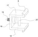
fig. 4 is a schematic view of a structure of a fitting fixture of a light trough installation structure according to an embodiment of the present invention.
1-lamp groove line, 2-fixed section bar, 3-sliding insertion strip, 4-sliding insertion groove, 5-matching fixing piece, 6-latch, 7-clamping groove, 8-first vertical connecting plate, 9-first upper limiting plate, 10-first lower limiting plate, 11-second vertical connecting plate, 12-second upper limiting plate, 13-second lower limiting plate, 14-insertion limiting hole, 15-insertion limiting shaft, 16-third vertical connecting plate, 17-third upper limiting plate, 18-third lower limiting plate, 19-fixing nail body and 20-elastic supporting piece.
Detailed Description
In order to make the objects, technical solutions and advantages of the embodiments of the present invention clearer, the embodiments of the present invention will be clearly and completely described below with reference to the accompanying drawings in the embodiments of the present invention, and it is obvious that the described embodiments are some, but not all, embodiments of the present invention. Based on the embodiments in the present invention, all other embodiments obtained by a person skilled in the art without creative work belong to the protection scope of the present invention. It should be noted that the embodiments and features of the embodiments in the present application may be arbitrarily combined with each other without conflict.
It is noted that, herein, relational terms such as first and second, and the like may be used solely to distinguish one entity or action from another entity or action without necessarily requiring or implying any actual such relationship or order between such entities or actions. Also, the terms "comprises," "comprising," or any other variation thereof, are intended to cover a non-exclusive inclusion, such that a process, method, article, or apparatus that comprises a list of elements does not include only those elements but may include other elements not expressly listed or inherent to such process, method, article, or apparatus. Without further limitation, an element defined by the phrase "comprising an …" does not exclude the presence of other identical elements in a process, method, article, or apparatus that comprises the element.
Please refer to fig. 1 to 4, the utility model discloses a light trough mounting structure of embodiment, including light trough lines 1, fixed profile 2, cooperation mounting 5, wherein cooperation mounting 5 is fixed in the limit portion recess of honeycomb panel with the help of the horizontal nail dress of staple body 19, fixed profile 2 and cooperation mounting 5 are with the help of latch 6, joint recess 7 mutual joint of structure is in order to fix the limit portion department at the honeycomb panel, and light trough lines 1 pegs graft with fixed profile 2 again and links to each other, light trough lines 1 can also be on fixed profile 2 lateral sliding in order to change the distance of adjusting plate in adjustment self to the furred ceiling structure, in order to make things convenient for the fluorescent tube to install.
As one of preferred items of this embodiment, the light trough line 1 includes a first vertical connecting plate 8 vertically arranged, and a first upper limiting plate 9 and a first lower limiting plate 10 integrally connected to two ends of the first vertical connecting plate 8, respectively, and the lower wall surface of the first lower limiting plate 10 is further provided with a sliding insertion strip 3. In this embodiment, the middle of the first lower limiting plate 10 is integrally connected to the lower end of the first vertical connecting plate 8, referring to the attached drawings, a plurality of inserting limiting holes 14 are formed at the right end of the first lower limiting plate 10 and between two adjacent sliding inserting strips 3 at equal intervals, after the light trough line 1 is transversely slid to a proper distance, and after one inserting limiting shaft 15 is inserted into two inserting limiting holes 14 which are overlapped with each other, the relative positions of the light trough line 1 and the fixed section bar 2 can be fixed without change.
In addition, the fixed section bar 2 connected with the light trough line 1 in a sliding insertion manner further comprises a second vertical connecting plate 11 which is vertically arranged, and a second upper limiting plate 12 and a second lower limiting plate 13 which are respectively connected to two ends of the second vertical connecting plate 11, wherein a sliding insertion groove 4 is formed in the upper surface of the second upper limiting plate 12, and the light trough line 1 and the fixed section bar 2 are mutually connected in a sliding insertion manner at the upper and lower positions. When the fixing profile 2 is fixed at the edge of the honeycomb panel, the second upper limiting plate 12 is positioned above the upper panel of the honeycomb panel, and the second lower limiting plate 13 is positioned below the lower layer of the honeycomb panel.
The mating fixture 5 also comprises a third vertical connecting plate 16, a third upper limiting plate 17 connected to the upper end of the third vertical connecting plate 16, and a third lower limiting plate 18 connected to the third vertical connecting plate 16 and located below the third upper limiting plate 17, wherein the third lower limiting plate 18 and the third upper limiting plate 17 are parallel to each other and located on the same side of the third vertical connecting plate 16. The cooperation mounting 5 inserts and installs in the limit portion recess of honeycomb panel and accomplishes fixedly with the help of the staple body 19, and the department of the limit portion of installing at the honeycomb panel of fixed section bar 2 still with cooperation mounting 5 joint to realize the light trough installation.
As a second preferred aspect of the present embodiment, when the fitting fixture 5 is installed in the edge groove of the honeycomb panel, the fixing nail body 19 is laterally nailed through the third vertical connecting plate 16 from right to left, and simultaneously nailed through the inner structural ribs having a larger thickness than the upper and lower surface layers of the honeycomb panel, so as to stably fix the fitting fixture 5 at the edge of the honeycomb panel. And the distance between the third lower limiting plate 18 and the third upper limiting plate 17 is smaller than the vertical width of the third vertical connecting plate 16, when the third vertical connecting plate 16 is matched with the third lower limiting plate 18 and is contacted and attached with the lower panel of the honeycomb panel, the lower panel of the honeycomb panel is required to be bent for two sections at the edge position to attach the matching fixing piece 5, so that the matching fixing piece 5 is clamped conveniently, and the matching fixing piece 5 is equivalently fixed and positioned before being completely fixed.
When the subsequent fixed section bar 2 is installed at the edge part of the honeycomb panel again, the second lower limiting plate 13 of the fixed section bar 2 is matched with the third upper limiting plate 17 to clamp the lower surface layer of the honeycomb panel, and the lower surface layer can be kept flush with the left end surface of the honeycomb panel, so that the concave-convex installation traces are not known.
As a third preferred item of this embodiment, the latch 6 is integrally disposed at one end of the third upper limiting plate 17 and the third lower limiting plate 18 away from the third vertical connecting plate 16, and the latch 6 forms an acute included angle with the third upper limiting plate 17 and the third lower limiting plate 18 respectively to form a barb structure. One ends of the second upper limiting plate 12 and the second lower limiting plate 13, which are close to the second vertical connecting plate 11, are provided with clamping grooves 7, and hook groove shapes are also formed. Thus, when the fixed sectional material 2 is connected with the matched fixing piece 5 in a clamping manner, the clamping effect can be stabilized, the fixed sectional material and the matched fixing piece can be detached without destructive disassembly, the stable connection effect is ensured, and the whole mounting structure can be repeatedly inserted, so that the lamp trough structure can be adjusted within a small range on site.
In addition, an elastic supporting member 20 is connected between the third upper limiting plate 17 and the third lower limiting plate 18. The elastic support 20 can keep the matching fixture 5 with proper opening force, and ensure the matching fixture 5 and the fixing section bar 2 to be tightly clamped.
Where not mentioned above, all are applicable to the prior art.
Finally, it should be noted that: the above embodiments are only used to illustrate the technical solution of the present invention, and not to limit it. Although the present invention has been described in detail with reference to the foregoing embodiments, it should be understood by those skilled in the art that: the technical solutions described in the foregoing embodiments may still be modified, or some technical features may be equivalently replaced; such modifications and substitutions do not depart from the spirit and scope of the present invention in its corresponding aspects.
Claims (9)
1. A light trough mounting structure is characterized in that: the honeycomb panel is characterized by comprising a light trough line (1) and a fixed section bar (2) which is connected with the light trough line (1) and fixed at the edge of a honeycomb panel, wherein sliding insertion strips (3) are arranged on the light trough line (1) side by side, a plurality of sliding insertion grooves (4) are correspondingly arranged on the fixed section bar (2), and the light trough line (1) is in sliding connection with the fixed section bar (2); the honeycomb plate fixing device further comprises a matching fixing piece (5) which is fixedly arranged at the edge part of the honeycomb plate and is in clamping connection with the fixing section bar (2), a clamping tooth (6) arranged on the matching fixing piece (5) and a clamping groove (7) correspondingly arranged on the fixing section bar (2); cooperation mounting (5) are fixed with the honeycomb panel nail dress, and cooperation mounting (5) are still arranged in fixed section bar (2) are installed in the enclosure space that forms when honeycomb panel limit portion department, cooperation mounting (5) still link to each other with fixed section bar (2) joint.
2. A troffer mounting structure according to claim 1, wherein: the light trough line (1) comprises a first vertical connecting plate (8), a first upper limiting plate (9) and a first lower limiting plate (10) which are respectively arranged at two ends of the first vertical connecting plate (8) and face to the same side of the first vertical connecting plate (8); the first lower limit plate (10) is integrally provided with a sliding insertion strip (3).
3. A troffer mounting structure according to claim 1, wherein: the fixed sectional material (2) comprises a second vertical connecting plate (11), a second upper limiting plate (12) and a second lower limiting plate (13) which are respectively arranged at two ends of the second vertical connecting plate (11) and face to the same side of the second vertical connecting plate (11); the second upper limiting plate (12) is provided with a sliding insertion groove (4).
4. A troffer mounting structure according to claim 3, wherein: the lamp groove line structure is characterized by further comprising a plurality of inserting limiting holes (14) formed between every two sliding inserting grooves (4) at equal intervals, inserting limiting holes (14) formed between every two sliding inserting strips (3) at equal intervals, and inserting limiting shafts (15) inserted into the two mutually overlapped inserting limiting holes (14) to limit the sliding position of the lamp groove line (1).
5. A troffer mounting structure according to claim 1, wherein: the matching fixing piece (5) comprises a third vertical connecting plate (16), a third upper limiting plate (17) arranged at one end of the third vertical connecting plate (16), and a third lower limiting plate (18) which is parallel to the third upper limiting plate (17) and is fixedly connected with the third vertical connecting plate (16).
6. A troffer mounting structure according to claim 5, wherein: the distance from the third lower limiting plate (18) to the third upper limiting plate (17) is less than the height of the third vertical connecting plate (16).
7. A troffer mounting structure according to claim 5, wherein: the honeycomb plate is characterized by also comprising a fixing nail body (19) which is nailed at the inner rib body of the honeycomb plate from the third vertical connecting plate (16) to fixedly match the fixing piece (5) and the edge part of the honeycomb plate.
8. A troffer mounting structure according to claim 5, wherein: an elastic supporting piece (20) is also connected and arranged between the third upper limiting plate (17) and the third lower limiting plate (18).
9. A troffer mounting structure according to claim 1, wherein: when the clamping teeth (6) are arranged on the matched fixing piece (5), the clamping teeth tend to be matched with the side wall of the fixing piece (5) to form a barb structure towards one side of the honeycomb plate during installation, and the corresponding clamping grooves (7) are also provided with hook groove shapes towards one side of the honeycomb plate.
Priority Applications (1)
| Application Number | Priority Date | Filing Date | Title |
|---|---|---|---|
| CN202120411736.3U CN214275627U (en) | 2021-02-25 | 2021-02-25 | Lamp slot mounting structure |
Applications Claiming Priority (1)
| Application Number | Priority Date | Filing Date | Title |
|---|---|---|---|
| CN202120411736.3U CN214275627U (en) | 2021-02-25 | 2021-02-25 | Lamp slot mounting structure |
Publications (1)
| Publication Number | Publication Date |
|---|---|
| CN214275627U true CN214275627U (en) | 2021-09-24 |
Family
ID=77792659
Family Applications (1)
| Application Number | Title | Priority Date | Filing Date |
|---|---|---|---|
| CN202120411736.3U Withdrawn - After Issue CN214275627U (en) | 2021-02-25 | 2021-02-25 | Lamp slot mounting structure |
Country Status (1)
| Country | Link |
|---|---|
| CN (1) | CN214275627U (en) |
Cited By (2)
| Publication number | Priority date | Publication date | Assignee | Title |
|---|---|---|---|---|
| CN112815278A (en) * | 2021-02-25 | 2021-05-18 | 浙江亚厦装饰股份有限公司 | Lamp slot mounting structure and mounting method thereof |
| CN114382221A (en) * | 2022-01-20 | 2022-04-22 | 深圳采骏绿碳供应链有限公司 | Assembly type ceiling lamp trough mounting structure |
-
2021
- 2021-02-25 CN CN202120411736.3U patent/CN214275627U/en not_active Withdrawn - After Issue
Cited By (4)
| Publication number | Priority date | Publication date | Assignee | Title |
|---|---|---|---|---|
| CN112815278A (en) * | 2021-02-25 | 2021-05-18 | 浙江亚厦装饰股份有限公司 | Lamp slot mounting structure and mounting method thereof |
| CN112815278B (en) * | 2021-02-25 | 2024-09-06 | 浙江亚厦装饰股份有限公司 | Lamp slot mounting structure and mounting method thereof |
| CN114382221A (en) * | 2022-01-20 | 2022-04-22 | 深圳采骏绿碳供应链有限公司 | Assembly type ceiling lamp trough mounting structure |
| CN114382221B (en) * | 2022-01-20 | 2023-09-26 | 深圳采骏绿碳供应链有限公司 | Assembled smallpox light trough mounting structure |
Similar Documents
| Publication | Publication Date | Title |
|---|---|---|
| CN111502105B (en) | A hook type ceiling installation structure | |
| CN212078415U (en) | Deformable card formula keel and curved surface furred ceiling mounting structure | |
| CN206233443U (en) | A kind of arc concealed light light slot structure | |
| CN112443076A (en) | Connecting member of ceiling decorative panel, ceiling system and mounting method | |
| CN111663706A (en) | Mounting structure and mounting method of suspended ceiling | |
| CN114607087B (en) | An assembled reverse step-down ceiling system | |
| CN110241966B (en) | Suspended ceiling device and installation method thereof | |
| KR100933525B1 (en) | Screen luba | |
| CN112815278A (en) | Lamp slot mounting structure and mounting method thereof | |
| CN215888802U (en) | Decorative panel splicing arc-shaped lamp groove decorative structure | |
| CN113374143B (en) | Suspended ceiling splice lamp strip structure and installation method | |
| CN115506531A (en) | Multifunctional suspended ceiling structure combination | |
| CN114319685A (en) | Assembled ceiling and installation method thereof | |
| CN209891542U (en) | Assembled wall installation component and wall | |
| CN214614968U (en) | Quick installation interlude fossil fragments formula pendant | |
| CN113530066B (en) | A kind of pre-installed fixing parts gap-leaving assembled ceiling and installation method | |
| CN216587274U (en) | Section bar and suspended ceiling system who uses thereof | |
| CN109750784B (en) | Lamp slot ceiling right angle module for preventing lamp slot right angle cracking and construction method | |
| CN205530911U (en) | Ceiling lamp groove device | |
| CN211447432U (en) | Clamping hook type horizontal adjustment combined structure for base layer of step top of light steel false beam | |
| CN112443129A (en) | Suspended ceiling modeling structure and mounting method thereof | |
| CN212427762U (en) | Structure for preventing middle deformation of ceiling board | |
| CN212427748U (en) | I-shaped part for connecting adjacent panels | |
| CN212926642U (en) | Connecting piece for decorative plate and assembling structure using same | |
| CN222667288U (en) | Hidden gap structure for spliced GRG (glass fiber reinforced glass) luminous suspended ceiling |
Legal Events
| Date | Code | Title | Description |
|---|---|---|---|
| GR01 | Patent grant | ||
| GR01 | Patent grant | ||
| AV01 | Patent right actively abandoned | ||
| AV01 | Patent right actively abandoned | ||
| AV01 | Patent right actively abandoned |
Granted publication date: 20210924 Effective date of abandoning: 20240906 |
|
| AV01 | Patent right actively abandoned |
Granted publication date: 20210924 Effective date of abandoning: 20240906 |