CN214269422U - Scraper type powder metering device - Google Patents
Scraper type powder metering device Download PDFInfo
- Publication number
- CN214269422U CN214269422U CN202022944212.9U CN202022944212U CN214269422U CN 214269422 U CN214269422 U CN 214269422U CN 202022944212 U CN202022944212 U CN 202022944212U CN 214269422 U CN214269422 U CN 214269422U
- Authority
- CN
- China
- Prior art keywords
- powder
- scraper
- bin
- measurement
- metering
- Prior art date
- Legal status (The legal status is an assumption and is not a legal conclusion. Google has not performed a legal analysis and makes no representation as to the accuracy of the status listed.)
- Active
Links
- 239000000843 powder Substances 0.000 title claims abstract description 78
- 238000005259 measurement Methods 0.000 claims abstract description 30
- 239000000463 material Substances 0.000 claims description 44
- 238000003860 storage Methods 0.000 claims description 9
- 238000007599 discharging Methods 0.000 claims description 7
- 230000002146 bilateral effect Effects 0.000 claims description 6
- 238000007790 scraping Methods 0.000 claims description 3
- 230000000149 penetrating effect Effects 0.000 claims 1
- 210000001364 upper extremity Anatomy 0.000 claims 1
- 238000004519 manufacturing process Methods 0.000 abstract description 6
- 238000000034 method Methods 0.000 description 6
- 238000010586 diagram Methods 0.000 description 1
- 239000002699 waste material Substances 0.000 description 1
- 238000005303 weighing Methods 0.000 description 1
Images


Landscapes
- Measuring Volume Flow (AREA)
Abstract
Scrape board-like powder metering device, store the storehouse including measurement seat and powder, the measurement seat is the cuboid structure, the top of measurement seat integrated into one piece all around has the open feed bin that connects in top, the vertical setting in storehouse is being connecing the feed bin to the powder, the lower extreme that the storehouse was stored to the powder is equipped with the unloading pipe, the equal fixed mounting in outside of the left side board and the right side board that connects the feed bin has the cylinder, the equal fixed mounting in piston rod right-hand member of left side cylinder and the piston rod left end of right side cylinder has the scraper blade, three measurement silo has been seted up on the measurement seat, the interval sets up about three measurement silo, measurement seat bottom is provided with three motor mounting groove, all install servo gear motor in every motor mounting groove, the equal vertical setting of three servo gear motor, three servo gear motor's power shaft lower extreme is fixedly connected with horizontal baffle respectively, three horizontal baffle correspond the lower port of the three measurement silo of shutoff respectively. The utility model relates to a science, the measurement is accurate, and easy operation avoids extravagant resource, can guarantee production quality.
Description
Technical Field
The utility model relates to a powder measuring tool field, specific theory relates to a scrape board-like powder metering device.
Background
In the wig manufacturing process, a large amount of powder is used for processing, wherein the amount of the powder needs to be measured every time so as to ensure the production quality and avoid resource waste, but the current operation is generally manual measurement and inaccurate measurement.
SUMMERY OF THE UTILITY MODEL
The utility model aims at providing a scrape board-like powder metering device, the utility model relates to a science, the measurement is accurate, and easy operation avoids extravagant resource, can guarantee production quality.
In order to achieve the above purpose, the utility model adopts the following technical scheme:
a scraper type powder metering device comprises a metering seat and a powder storage bin, wherein the metering seat is of a cuboid structure, the periphery of the bottom of the metering seat is fixed on the ground through supporting legs, the periphery of the top of the metering seat is integrally formed with a receiving bin with an open top, the powder storage bin is vertically arranged right above the receiving bin, a discharging pipe is arranged at the lower end of the powder storage bin, valves are arranged on the discharging pipe, horizontal supports are fixedly arranged on the outer portions of a left side plate and a right side plate of the receiving bin respectively, cylinders horizontally arranged along the left and right directions are fixedly arranged on the two horizontal supports respectively, a piston rod of a left side cylinder penetrates through a left side plate of the receiving bin rightwards and extends into the receiving bin, a piston rod of a right side cylinder penetrates through a right side plate of the receiving bin leftwards and extends into the receiving bin leftwards, scrapers vertically arranged along the front and back directions are fixedly arranged at the right end of a piston rod of the left side cylinder and at the left end of a piston rod of the right side cylinder, the lower side edge of the scraper is in sliding contact with the upper surface of the metering seat, the front side edge of the scraper is in sliding contact with the rear side surface of the front side plate of the receiving bin, the rear side edge of the scraper is in sliding contact with the front side surface of the rear side plate of the receiving bin, three vertically arranged and vertically through metering troughs are arranged on the metering seat, the three metering troughs are arranged at left and right intervals, the upper port of each metering trough is communicated with the inside of the receiving bin, three motor mounting grooves with lower openings are arranged at the bottom of the metering seat, the three motor mounting grooves are respectively and correspondingly positioned at one side of the lower side parts of the three metering troughs, a servo speed reducing motor is arranged in each motor mounting groove, a fixing plate for fixing the servo speed reducing motors is fixedly arranged at the lower port of each motor mounting groove through a first countersunk head screw, the three servo speed reducing motors are all vertically arranged, the lower ends of power shafts of the three servo speed reducing motors respectively correspondingly penetrate through the corresponding fixing plates and are fixedly connected with horizontal baffle plates, and the three horizontal baffles respectively and correspondingly block the lower ports of the three metering material tanks.
Connect the equal fixed mounting in top left side and the right side of feed bin to have a stock guide, the structure of two stock guides is the same and bilateral symmetry sets up, high low in the right side of left stock guide, the left side fixed connection of left stock guide connects the left side board right flank top edge portion of feed bin, the front side fixed connection of left stock guide connects the left upper left lateral part of the preceding curb plate trailing flank of feed bin, the back side fixed connection of left stock guide connects the left upper left lateral part of the trailing flank front flank of feed bin.
The equal fixed mounting in left surface middle part and the right side middle part of measurement seat has the powder collecting cylinder of remaining, and two structures that remain the powder collecting cylinder are the same and bilateral symmetry set up, connect the left side board downside middle part and the right side board downside middle part of feed bin and all seted up the bin outlet, and equal fixed mounting has and connects the row's material pipe of the inside intercommunication of feed bin between the top of left side bin outlet and left side remaining powder collecting cylinder and between the top of right side bin outlet and right side remaining powder collecting cylinder.
The lower side of the scraper is connected with a wear-resistant strip which is convenient to replace through a second countersunk head screw, and the lower side of the wear-resistant strip is in sliding contact with the upper surface of the metering seat.
The outer end of the piston rod of the cylinder is fixedly provided with a connecting plate parallel to the scraper, and the connecting plate is attached to the scraper and connected with the scraper into a whole through a bolt.
The utility model discloses relative prior art has substantive characteristics and progress, specifically speaking, the utility model discloses the working process is: initially, piston rods of two cylinders are in a completely contracted state, a left scraper is positioned at the left side part in a material receiving bin, the left side surface of the left scraper is contacted with the right side surface of a left side plate of the material receiving bin, a right scraper is positioned at the right side part in the material receiving bin, the right side surface of the right scraper is contacted with the left side surface of the right side plate of the material receiving bin, three horizontal baffles respectively and correspondingly seal lower ports of three metering material tanks, a valve on a blanking pipe is opened to ensure that a certain amount of powder is discharged from a powder storage bin into the material receiving bin through a blanking pipe, two material guide plates prevent the powder from falling on the left side and the right side of the bottom in the material receiving bin to ensure that the powder is accumulated in the middle part of the upper surface of a metering seat between the two scraper plates, then the valve is closed to stop blanking, the left cylinder is started firstly, the piston rod of the left cylinder pushes, the left scraper scrapes the powder in the middle of the material receiving bin to the position between the rightmost metering trough and the right scraper, in the process, the three metering troughs are all filled with the powder, the upper ports in the three metering troughs are all filled with the powder, if one or more metering troughs are not filled, the piston rod of the air cylinder on the left side is controlled to shrink leftwards to the initial position, the piston rod of the air cylinder on the left side drives the scraper on the left side to move leftwards to the initial position, then the air cylinder on the right side is started, the piston rod of the air cylinder on the right side pushes the scraper on the right side leftwards, so that the scraper on the right side moves leftwards to the left part of the material receiving bin and is positioned between the leftmost metering trough and the left scraper, the scraper on the right side scrapes the powder in the material receiving bin to the position between the leftmost metering trough and the left scraper, in the process, the powder continues to be filled in the three metering troughs, if one or more metering troughs are not filled, controlling the piston rod of the air cylinder on the right to contract rightwards to the initial position, driving the scraper on the right to move rightwards to the initial position by the piston rod of the air cylinder on the right, starting the air cylinder on the left, repeating the operation, scraping the powder in the storage bin in a left-right reciprocating manner by the scraper on the left and the scraper on the right until the three metering material tanks are all filled with the powder, then rotating the corresponding horizontal baffle plate by the corresponding servo speed reduction motor by 90 degrees according to the required powder amount, opening the lower port of the corresponding metering material tank, dropping the powder in the corresponding metering material tank from the lower port, sequentially increasing the volume of the three metering material tanks from left to right, and when the three metering material tanks are filled with the powder, respectively weighing 1Kg, 2 Kg and 5 Kg of the powder in any integer weight larger than 1Kg, thus being capable of accumulating and being scientific in design, the metering is accurate, and easy operation avoids extravagant resource, can guarantee production quality to set up two and remain the powder collecting vessel, the deposit can enter into two through arranging the material pipe and remain in the powder collecting vessel on bottom left side and right side in connecing the material storehouse, resources are saved.
Drawings
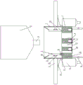
Fig. 1 is a schematic structural diagram of the present invention.
Fig. 2 is a plan view of the metering base of the present invention.
Fig. 3 is a partially enlarged view of a portion a in fig. 1.
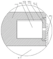
Fig. 4 is a partial enlarged view of fig. 1 at B.
Detailed Description
The embodiments of the present invention will be further explained with reference to the drawings.
Example 1
As shown in figures 1-4, scrape board-like powder metering device, store storehouse 2 including measurement seat 1 and powder, measurement seat 1 is the cuboid structure, the bottom of measurement seat 1 is fixed subaerial through landing leg 14 all around, integrated into one piece has the open storehouse 3 that connects in top all around the top of measurement seat 1, the vertical setting in storehouse 2 is being connect directly over the storehouse 3 to the powder, the lower extreme that storehouse 2 was stored to the powder is equipped with unloading pipe 4, be equipped with the valve (not shown) on the unloading pipe 4, the equal fixed mounting in the outside of the left side board that connects storehouse 3 and the right side board has horizontal support 15, equal fixed mounting has the cylinder 5 along the horizontal setting of left and right direction on two horizontal support 15, the piston rod of left side cylinder 5 passes the left side board that connects storehouse 3 right and stretches into and connects the storehouse 3 in, the piston rod of right side cylinder 5 passes the right side board that connects storehouse 3 left and stretches into and connects the storehouse 3, the piston rod right-hand member of left side cylinder 5 and the equal fixed mounting of the piston rod of right-hand member of right side cylinder 5 have along the front and back The device comprises a vertically arranged scraper 6, the lower side edge of the scraper 6 is in sliding contact with the upper surface of a metering seat 1, the front side edge of the scraper 6 is in sliding contact with the rear side surface of the front side plate of a material receiving bin 3, the rear side edge of the scraper 6 is in sliding contact with the front side surface of the rear side plate of the material receiving bin 3, three vertically arranged and vertically through metering troughs 7 are arranged on the metering seat 1, the three metering troughs 7 are arranged at left and right intervals, the upper port of each metering trough 7 is communicated with the interior of the material receiving bin 3, three motor mounting grooves 16 with lower openings are arranged at the bottom of the metering seat 1, the three motor mounting grooves 16 are respectively correspondingly positioned at one side of the lower side parts of the three metering troughs 7, a servo speed reducing motor 8 is arranged in each motor mounting groove 16, a fixing plate 18 for fixing the servo speed reducing motor 8 is fixedly arranged at the lower port of each motor mounting groove 16 through a first countersunk head screw 17, and the three servo speed reducing motors 8 are all vertically arranged, the lower ends of power shafts of the three servo speed reducing motors 8 respectively and correspondingly penetrate through the corresponding fixing plates 18 and are fixedly connected with the horizontal baffles 9, and the three horizontal baffles respectively and correspondingly block the lower ports of the three metering material tanks 7.
Connect the equal fixed mounting in top left side and the right side of feed bin 3 to have a stock guide 10, two stock guide 10's the same and bilateral symmetry setting of structure, left stock guide 10 high-low on the left side, left side fixed connection of left stock guide 10 is in the left side board right flank top edge portion that connects feed bin 3, left stock guide 10's preceding side fixed connection is in the preceding curb plate trailing flank upper left lateral part that connects feed bin 3, left stock guide 10's back side fixed connection is in the back side board leading flank upper left lateral part that connects feed bin 3, left stock guide 10 right flank is a little higher than scraper blade 6's last side.
The equal fixed mounting in left surface middle part and the right side middle part of measurement seat 1 has and remains powder collecting cylinder 11, and two structures that remain powder collecting cylinder 11 are the same and bilateral symmetry set up, connect left side board downside middle part and right side board downside middle part of feed bin 3 and all seted up bin outlet 12, and equal fixed mounting has and connects the row's material pipe 13 of the inside intercommunication of feed bin 3 between the top of left side bin outlet 12 and left side remaining powder collecting cylinder 11 and between the top that right side bin outlet 12 and right side remaining powder collecting cylinder 11.
The volumes of the three metering material tanks 7 are sequentially increased from left to right, and when the three metering material tanks 7 are filled with powder, the weights of the powder in the three metering material tanks 7 are 1Kg, 2 Kg and 5 Kg respectively, so that the powder with the weight of any integer larger than 1Kg can be obtained in an accumulated manner.
The utility model discloses the working process does: initially, piston rods of two cylinders 5 are all in a completely contracted state, a left scraper 6 is positioned at the left side part in a material receiving bin 3, the left side surface of the left scraper 6 is contacted with the right side surface of a left side plate of the material receiving bin 3, a right scraper 6 is positioned at the right side part in the material receiving bin 3, the right side surface of the right scraper 6 is contacted with the left side surface of the right side plate of the material receiving bin 3, three horizontal baffles respectively and correspondingly seal the lower ports of three metering material tanks 7, a valve on a discharging pipe 4 is opened, a certain amount of powder is discharged from a powder storage bin 2 to the material receiving bin 3 through the discharging pipe 4, two material guide plates 10 prevent the powder from falling at the left side and the right side of the bottom in the material receiving bin 3, the powder is ensured to be accumulated in the middle part of the upper surface of a metering seat 1 positioned between the two scraper 6, then the valve is closed, the discharging is stopped, the left cylinder 5 is started first, the piston rod of the left cylinder 5 pushes the left scraper 6 to the right, the left scraper 6 is moved to the right side of the material receiving bin 3 and is positioned between the rightmost metering trough 7 and the right scraper 6, the left scraper 6 scrapes the powder in the middle of the material receiving bin 3 to the position between the rightmost metering trough 7 and the right scraper 6, in the process, the three metering troughs 7 are filled with the powder, the upper ports in the three metering troughs 7 are filled with the powder, if one or more metering troughs 7 are not filled, the piston rod of the left cylinder 5 is controlled to shrink to the initial position leftwards, the piston rod of the left cylinder 5 drives the left scraper 6 to move leftwards to the initial position, then the right cylinder 5 is started, the piston rod of the right cylinder 5 pushes the right scraper 6 leftwards, and the right scraper 6 moves leftwards to the left side of the material receiving bin 3 and is positioned between the leftmost metering trough 7 and the left scraper 6, the scraper 6 on the right scrapes the powder in the material receiving bin 3 to a position between the leftmost metering hopper 7 and the left scraper 6, in the process, the powder is continuously filled in the three metering hoppers 7, if one or more metering hoppers 7 are still not filled, the piston rod of the cylinder 5 on the right is controlled to be contracted rightwards to the initial position, the piston rod of the cylinder 5 on the right drives the scraper 6 on the right to move rightwards to the initial position, the cylinder 5 on the left is started again, the operation is repeated, the left scraper 6 and the right scraper 6 on the left scrape the powder in the material receiving bin 3 in a left-right reciprocating manner until the three metering hoppers 7 are all filled with the powder, then, according to the required powder amount, the corresponding horizontal baffle is rotated by 90 degrees through the corresponding servo speed reducing motor 8, the lower port of the corresponding metering hopper 7 is opened, and the powder in the corresponding metering hopper 7 falls down from the lower port, the volume of three measurement silo 7 increases in proper order from the left hand right side, when the powder is full of three measurement silo 7, the powder weight in the three measurement silo 7 is 1Kg respectively, 2 Kg and 5 Kg, can add up the powder that obtains the arbitrary integer weight that is greater than 1Kg like this, the measurement is accurate, therefore, the operation is simple, avoid wasting of resources, can guarantee production quality, and set up two and remain powder collecting cylinder 11, the deposit is in connecing material storehouse 3 interior bottom left side and the remaining powder on right side and can enter into two through arranging material pipe 13 and remain in powder collecting cylinder 11, the design science, and resources are saved.
Example 2, in contrast to example 1:
the lower side of the scraper 6 is connected with a wear-resistant strip 20 convenient to replace through a second countersunk screw 19, and the lower side of the wear-resistant strip 20 is in sliding contact with the upper surface of the metering seat 1.
The outer end of the piston rod of the cylinder 5 is fixedly provided with a connecting plate 21 parallel to the scraper 6, and the connecting plate 21 is attached to the scraper 6 and connected into a whole through a bolt 22.
Therefore, after the wear-resistant strips 20 are worn, the bolts 22 can be screwed off, the scraper 6 is detached from the connecting plate 21, the second countersunk screws 19 are detached, the wear-resistant strips 20 are detached, new wear-resistant strips 20 are replaced, the new wear-resistant strips 20 are installed on the lower side edge of the scraper 6 through the second countersunk screws 19 again, and the scraper 6 is connected with the connecting plate 21 again into a whole through the bolts 22.
The above embodiments are only used for illustrating but not limiting the technical solution of the present invention, and although the present invention is described in detail with reference to the above embodiments, those of ordinary skill in the art should understand that; the present invention may be modified or substituted with equivalents without departing from the spirit and scope of the invention, which should be construed as being limited only by the claims.
Claims (5)
1. Scrape board-like powder metering device, its characterized in that: the device comprises a metering seat and a powder storage bin, wherein the metering seat is of a cuboid structure, the periphery of the bottom of the metering seat is fixed on the ground through supporting legs, the periphery of the top of the metering seat is integrally formed with a receiving bin with an open top, the powder storage bin is vertically arranged right above the receiving bin, a discharging pipe is arranged at the lower end of the powder storage bin, a valve is arranged on the discharging pipe, horizontal supports are fixedly arranged on the outer portions of a left side plate and a right side plate of the receiving bin respectively, cylinders horizontally arranged along the left and right directions are fixedly arranged on the two horizontal supports respectively, a piston rod of the left side cylinder penetrates through the left side plate of the receiving bin rightwards and extends into the receiving bin, a piston rod of the right side cylinder penetrates through the right side plate of the receiving bin leftwards and extends into the receiving bin, scraping plates vertically arranged along the front and back directions are fixedly arranged at the right end of the piston rod of the left side cylinder and the left end of the piston rod of the right side cylinder, and the lower side edge of the scraping plates is in sliding contact with the upper surface of the metering seat, the preceding side of scraper blade and the preceding curb plate trailing flank sliding contact who connects the feed bin, the trailing flank of scraper blade and the trailing flank sliding contact who connects the feed bin, three vertical setting and upper and lower penetrating measurement silo have been seted up on the measurement seat, the interval sets up about three measurement silo, the last port of measurement silo with connect the inside intercommunication of feed bin, measurement seat bottom is provided with the open motor mounting groove of three downside, three motor mounting groove corresponds the lower side portion one side that is located three measurement silo respectively, all install servo gear motor in every motor mounting groove, the lower port of every motor mounting groove all has the fixed plate that is used for fixed servo gear motor through first countersunk screw fixed mounting, the equal vertical setting of three servo gear motor, three servo gear motor's power shaft lower extreme corresponds respectively and passes corresponding fixed plate and fixed connection has horizontal baffle, three horizontal baffle correspond the lower port of the three measurement silos of shutoff respectively.
2. The scraper powder metering device of claim 1, characterized in that: connect the equal fixed mounting in top left side and the right side of feed bin to have a stock guide, the structure of two stock guides is the same and bilateral symmetry sets up, high low in the right side of left stock guide left side, the left side fixed connection of left stock guide is in the left side board right flank upper limb portion that connects the feed bin, the front side fixed connection of left stock guide is in the front side board trailing flank upper left side lateral part that connects the feed bin, the rear side fixed connection of left stock guide is in the rear side board leading flank upper left side lateral part that connects the feed bin, the left stock guide right side is a little higher than the last side of scraper blade.
3. The scraper powder metering device of claim 2, characterized in that: the equal fixed mounting in left surface middle part and the right side middle part of measurement seat has the powder collecting cylinder of remaining, and two structures that remain the powder collecting cylinder are the same and bilateral symmetry set up, connect the left side board downside middle part and the right side board downside middle part of feed bin and all seted up the bin outlet, and equal fixed mounting has and connects the row's material pipe of the inside intercommunication of feed bin between the top of left side bin outlet and left side remaining powder collecting cylinder and between the top of right side bin outlet and right side remaining powder collecting cylinder.
4. The scraper powder metering device as claimed in claim 3, wherein: the lower side of the scraper is connected with a wear-resistant strip which is convenient to replace through a second countersunk head screw, and the lower side of the wear-resistant strip is in sliding contact with the upper surface of the metering seat.
5. The scraper powder metering device as claimed in claim 4, wherein: the outer end of the piston rod of the cylinder is fixedly provided with a connecting plate parallel to the scraper, and the connecting plate is attached to the scraper and connected with the scraper into a whole through a bolt.
Priority Applications (1)
| Application Number | Priority Date | Filing Date | Title |
|---|---|---|---|
| CN202022944212.9U CN214269422U (en) | 2020-12-10 | 2020-12-10 | Scraper type powder metering device |
Applications Claiming Priority (1)
| Application Number | Priority Date | Filing Date | Title |
|---|---|---|---|
| CN202022944212.9U CN214269422U (en) | 2020-12-10 | 2020-12-10 | Scraper type powder metering device |
Publications (1)
| Publication Number | Publication Date |
|---|---|
| CN214269422U true CN214269422U (en) | 2021-09-24 |
Family
ID=77780594
Family Applications (1)
| Application Number | Title | Priority Date | Filing Date |
|---|---|---|---|
| CN202022944212.9U Active CN214269422U (en) | 2020-12-10 | 2020-12-10 | Scraper type powder metering device |
Country Status (1)
| Country | Link |
|---|---|
| CN (1) | CN214269422U (en) |
Cited By (3)
| Publication number | Priority date | Publication date | Assignee | Title |
|---|---|---|---|---|
| CN113751191A (en) * | 2021-10-09 | 2021-12-07 | 泰德(天津)工业技术有限公司 | Accurate quantitative continuous coal slime sorter tailings discharging mechanism |
| CN113942143A (en) * | 2021-10-25 | 2022-01-18 | 浙江益弹新材料科技有限公司 | Aliphatic thermoplastic polyurethane elastomer production equipment |
| CN115057608A (en) * | 2022-05-31 | 2022-09-16 | 甘肃光轩高端装备产业有限公司 | Powder measuring bin, powder measuring and feeding device and system |
-
2020
- 2020-12-10 CN CN202022944212.9U patent/CN214269422U/en active Active
Cited By (3)
| Publication number | Priority date | Publication date | Assignee | Title |
|---|---|---|---|---|
| CN113751191A (en) * | 2021-10-09 | 2021-12-07 | 泰德(天津)工业技术有限公司 | Accurate quantitative continuous coal slime sorter tailings discharging mechanism |
| CN113942143A (en) * | 2021-10-25 | 2022-01-18 | 浙江益弹新材料科技有限公司 | Aliphatic thermoplastic polyurethane elastomer production equipment |
| CN115057608A (en) * | 2022-05-31 | 2022-09-16 | 甘肃光轩高端装备产业有限公司 | Powder measuring bin, powder measuring and feeding device and system |
Similar Documents
| Publication | Publication Date | Title |
|---|---|---|
| CN207209472U (en) | Efficient multi-cavity automatic material weighing machine | |
| CN202807119U (en) | A metering device and noodle weighing mechanism using the metering device | |
| CN220389884U (en) | Trace additive metering system for dry-mixed mortar | |
| CN221620272U (en) | Filling machine clearance mechanism | |
| CN209566281U (en) | A kind of block building machine | |
| CN202807162U (en) | A measuring cup assembly and noodle weighing mechanism utilizing the measuring cup assembly | |
| CN214112942U (en) | Silkworm egg quantitative boxing machine | |
| CN104477629A (en) | Sand conveyor test device and method | |
| CN204341939U (en) | Sediment transport machine experimental set-up | |
| CN221182595U (en) | Batching dispensing device of tailing sand | |
| CN110921250B (en) | Intelligent preserved fruit adding and stirring device and using method thereof | |
| CN210546186U (en) | Seed sorting device | |
| CN222947713U (en) | Automatic powder adding machine and full-automatic material-adding popcorn production line | |
| CN222841998U (en) | Continuous slurry preparation device | |
| CN223703057U (en) | Hotpot condiment filling machine with quantitative bagging function | |
| CN209718693U (en) | A kind of disk molding machine of adjustable type | |
| CN109204904A (en) | A kind of automatic weighting baling press | |
| CN210310950U (en) | Quantitative racking machine for viscous materials | |
| CN220640431U (en) | Quantitative weighing and packing device | |
| CN217791295U (en) | Minced fillet forming machine convenient to control weight | |
| CN220664870U (en) | Water paint production is with filling weighing device | |
| CN219495425U (en) | Anti-caking agent production is with batching weighing device | |
| CN218628471U (en) | Metering device is used in antirust oil processing | |
| CN216884612U (en) | Combination feeding bin convenient to concrete aggregate is changed | |
| CN222956253U (en) | Quantitative coating blending device |
Legal Events
| Date | Code | Title | Description |
|---|---|---|---|
| GR01 | Patent grant | ||
| GR01 | Patent grant |